Transcription
LASERJET ENTERPRISE M604, M605,M606Maintenance kit replacement tions used in this guideTIP: Tips provide helpful hints or shortcuts.NOTE:Notes provide important information to explain a concept or to complete a task.CAUTION: Cautions indicate procedures that you should follow to avoid losing data or damaging theproduct.WARNING! Warnings alert you to specific procedures that you should follow to avoid personal injury,catastrophic loss of data, or extensive damage to the product.
Table of ContentsRemoval and replacement . 7For additional service and support. 8Removal and replacement strategy . 9Introduction. 9Considerations during removal and replacement . 9Electrostatic discharge. 11Required tools . 11Types of screws. 12Fasteners used in the printer. 12Removal and replacement: Fuser . 13Introduction . 13Step 1: Remove the duplex accessory . 14Step 2: Remove the duplex accessory cover . 14Step 3: Remove the rear output bin . 15Step 4: Remove the fuser. 16Step 5: Unpack the replacement fuser . 17Step 6: Install the fuser. 17Step 7: Install the rear output bin. 18Step 8: Install the duplex accessory cover. 19Step 9: Install the duplex accessory . 19Removal and replacement: Transfer roller . 20Introduction . 20Step 1: Remove the toner cartridge . 21Step 2: Remove the transfer roller . 22Step 3: Unpack the replacement transfer roller . 23Step 4: Install the transfer roller. 23Step 5: Install the toner cartridge . 25Removal and replacement: Pickup, feed, and separation rollers (Trays 2-6 and 1,500-sheet high- . 26capacity input feeder) . 26Introduction . 26Step 1: Remove the tray. 27Step 2: Remove the pickup, feed, and separation rollers (trays 2-6). 28Step 3: Unpack the replacement pickup, feed, and separation rollers . 29Step 4: Install the pickup, feed, and separation rollers (trays 2-6) . 30Step 5: Install the tray . 32Step 6: Remove the pickup, feed, and separation rollers (HCI) . 32Step 7: Unpack the replacement pickup, feed, and separation rollers . 35Step 8: Install the pickup, feed, and separation rollers (HCI) . 35Removal and replacement: Fuser motor . 37Introduction . 37Step 1: Remove the right cover . 38Step 2: Remove the DC controller . 40Step 3: Remove the formatter and formatter case . 42Step 4: Remove the fuser motor . 47Step 5: Unpack the replacement fuser motor . 49Step 6: Install the fuser motor. 51Page 2
Step 7: Install the DC controller . 52Step 8: Install the formatter and formatter case . 54Step 9: Install the right cover . 58Removal and replacement: Trays 2-6 . 61Introduction . 61Step 1: Remove the tray . 62Step 2: Unpack the replacement tray. 62Step 3: Install the tray . 63Page 3
List of FiguresFigure 1.Figure 2.Figure 3.Figure 4.Figure 5.Figure 6.Figure 7.Figure 8.Figure 9.Figure 10.Figure 11.Figure 12.Figure 13.Figure 14.Figure 15.Figure 16.Figure 17.Figure 18.Figure 19.Figure 20.Figure 21.Figure 22.Figure 23.Figure 24.Figure 25.Figure 26.Figure 27.Figure 28.Screwdrivers.10Screw size chart .11Remove the duplex accessory . 13Remove the duplex accessory cover .13Release the hinge pin .14Remove the output bin . 14Squeeze the blue fuser-release tabs . 15Remove the fuser . 15Recycle and unpack .16Install the fuser .16Position the output bin .17Install left hinge pin . 17Install the duplex accessory cover . 18Install the duplex accessory . 18Open the cartridge door. 20Remove the toner cartridge .20Unpack the transfer-roller removal hook . 21Lift the left side of the transfer roller . 22Recycle and unpack .22Wear the protective gloves . 23Install the right end of the transfer roller . 23Install the left end of the transfer roller . 24Install the toner cartridge . 24Close the cartridge door . 25Remove the tray .26Open the cover .27Remove the feed roller . 27Remove the feed roller . 27Page 4
Figure 29.Figure 30.Figure 31.Figure 32.Figure 33.Figure 34.Figure 35.Figure 36.Figure 37.Figure 38.Figure 39.Figure 40.Figure 41.Figure 42.Figure 43.Figure 44.Figure 45.Figure 46.Figure 47.Figure 48.Figure 49.Figure 50.Figure 51.Figure 52.Figure 53.Figure 54.Figure 55.Figure 56.Recycle and unpack .28Install the pick roller . 29Install the feed roller .29Open the cover .30Align the torque limiter .30Install the feed roller .31Install the tray .31Open the feeder door . 32Open the separation-roller cover . 32Remove the separation roller . 33Remove the feed roller . 33Remove the pick roller. 34Recycle and unpack .34Install the pick roller . 35Install the feed roller .35Open the separation-roller cover . 36Open the front cover and cartridge door . 37Remove two screws .38Release three tabs .38Remove the cover. 39ZIF connector .39Disconnect the connectors. 40Remove two screws and release one tab . 40Remove the DC controller . 41Open the formatter case door . 41ZIF connector .42Disconnect all connectors .42Remove two screws .43Page 5
Figure 57.Figure 58.Figure 59.Figure 60.Figure 61.Figure 62.Figure 63.Figure 64.Figure 65.Figure 66.Figure 67.Figure 68.Figure 69.Figure 70.Figure 71.Figure 72.Figure 73.Figure 74.Figure 75.Figure 76.Figure 77.Figure 78.Figure 79.Figure 80.Figure 81.Figure 82.Figure 83.Figure 84.Figure 85.Remove the wires from the formatter case . 43Feed cables through the openings . 44Remove formatter case . 44Locate the fuser motor .45Release one spring .45Remove two screws .46Remove the bracket .46Remove the fuser motor . 47Recycle and unpack .47Install the fuser motor .48Position the bracket .48Install two screws . 49Attach one spring .49Position the DC controller on the printer . 50Install two screws . 50ZIF connector .51Connect the connectors. 51Position the formatter case . 52Install the formatter case . 52Position the wires in the formatter case . 53Install two screws . 53ZIF connector .54Connect all connectors .54Close the formatter case door . 55Note location of tabs .55Position the front tabs . 56Slide the cover .56Install two screws . 57Close the front cover and cartridge door . 57Page 6
Figure 86.Figure 87.Figure 88.Remove the tray .59Recycle and unpack .59Install the tray .60Removal and replacement For additional service and support Removal and replacement strategyPage 7
For additional service and supportHP service personnel, go to the Service Access Work Bench (SAW) athttp://h41302.www4.hp.com/km/saw/ home.do.Channel partners, go to HP Channel Services Network (CSN) at https://h30125.www3.hp.com/hpcsn. To access HP PartSurfer information from any mobile device, go to http://partsurfermobile.hp.com/ orscan the Quick Response (QR) code below. Install and configure Printer specifications Up to date control-panel message (CPMD) troubleshooting Solutions for printer issues and emerging issues Remove and replace part instructions and videos Service advisories Warranty & regulatory informationPage 8
Removal and replacement strategyIntroductionThe printer uses a field repair strategy. Defective parts are diagnosed and replaced at the FieldReplaceable Unit (FRU) assembly level. Repair normally begins by using the printer internal diagnosticsand the following two-step process:Isolate the problem to the major system (for example, the network or server, or the printer.Troubleshoot the problem by using the procedures in the troubleshooting chapter.After locating a faulty part, the printer can usually be repaired at the assembly level by replacing FRUs.Some mechanical assemblies might need to be repaired at the subassembly level. Hewlett-PackardCompany does not support replacement of components on the printed circuit assembles.The user replaces toner cartridges as they are depleted. Additional instructions about otheruserreplaceable parts are provided in this section.The printer tracks the amount of use on the customer-replaceable supplies by keeping a page count. Theprinter prompts the user to replace certain items when a supply is depleted or a specific number of pageshas been printed.Swapping toner cartridges between products might cause a misrepresentation of supply life values and isnot recommended.Considerations during removal and replacementThis chapter describes the removal and replacement of field-replaceable units (FRUs) only.Replacing FRUs is generally the reverse of removal. Notes are included to provide directions for difficult orcritical replacement procedures.HP does not support repairing individual subassemblies or troubleshooting to the printed-circuit assembly(PCA) component level.WARNING! Never operate or service the printer with the protective cover removed from the laserscanner assembly. The reflected beam, although invisible, can cause damage to the eyes.The sheet-metal parts can have sharp edges. Be careful when handling sheet-metal parts.Turn the printer off, wait 5 seconds, and then remove the power cord before attempting to service theprinter. If this warning is not followed, severe injury can result as well as damage to the printer. The powermust be on for certain functional checks during troubleshooting. However, the power cord must bedisconnected during parts removal. AC voltage is still present inside the printer when the power switch isin the off position. The power cord must be disconnected before servicing the product.CAUTION: Incorrectly routed or loose wire harnesses might interfere with other internal components orassemblies and be damaged, pinched, or frayed. Make sure that wire harnesses are correctly routed andretained when installing assemblies.Do not bend or fold the flat flexible cables (FFCs) during removal or installation.Do not expose the toner cartridge or cartridges, to strong light even for a short time.Page 9
IMPORTANT: When an assembly is removed that includes a rating plate or tag (or a printer code label),make sure to transfer the plate or tag (or code label) to the replacement assembly.Page 10
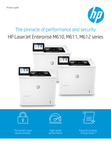
Do not replace the formatter, DC controller, and eMMC PCA or hard-disk drive simultaneously during asingle printer servicing. Doing so might cause the printer to become unstable or inoperable.NOTE: During assembly removal and replacement, or if the printer is moved, remove the toner cartridge orcartridges.Toner is a non-poisonous substance composed of plastic and a small number of colored components. Iftoner gets on the skin or clothing, wipe it off with dry tissue paper and wash in cold water. Hot water setstoner and it might be difficult, or impossible, to remove. Toner easily breaks down vinyl materials, so avoidletting toner contact with vinyl.TIP: Some figures might show assemblies removed or installed that have not yet been removed or installedat that specific step. However, the procedures are correct for this printer and the target assembly. Alwaysthoroughly read the instructions that accompany each figure.Electrostatic dischargeSome parts are sensitive to electrostatic discharge (ESD). Look for the ESD reminderCAUTION:when removing printer parts. Always perform service work at an ESD-protected workstation or mat. If anESD workstation or mat is not available, touch the sheet-metal chassis to provide a static ground beforetouching an ESD-sensitive assembly.Protect the ESD-sensitive assemblies by placing them in ESD pouches when they are out of the printer.Required tools #2 Phillips screwdriver with a magnetic tip and a 152-mm ( (6-in)) shaft length Small, flat-blade screwdriver Needle-nose pliers ESD strap (if one is available) PenlightCAUTION: Always use a Phillips screwdriver (callout 1). Do not use a Pozidriv screwdriver (callout 2) orany motorized screwdriver. These can damage screws or screw threads.Figure 1.ScrewdriversPage 11
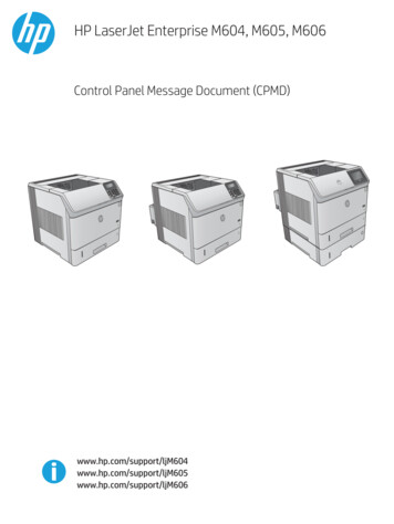
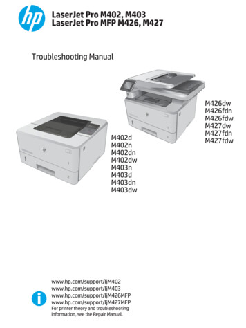
Types of screwsWARNING! Make sure that assemblies are replaced with the correct screw type. Using the incorrectscrew (for example, substituting a long screw for the correct shorter screw) can cause damage to theprinter or interfere with printer operation. Do not intermix screws that are removed from one assembly withthe screws that are removed from another assembly.NOTE: To install a self-tapping screw, first turn it counterclockwise to align it with the existing threadpattern, and then carefully turn it clockwise to tighten. Do not overtighten. If a self-tapping screw-holebecomes stripped, repair the screw-hole or replace the affected assembly.Always take note of the length, diameter, color, type, and location of each removed screw. Make sure thatscrews are installed in the original location they were removed from during reinstallation.Fasteners used in the printer Screw, BH M3X10 Screw, with washer, M3X8 Screw, D M3X8 Screw, machine, truss head, M3X6Figure 2.Screw size chartPage 12
Removal and replacement: Fuser Introduction Step 1: Remove the duplex accessory Step 2: Remove the duplex accessory cover Step 3: Remove the rear output bin Step 4: Remove the fuser Step 5: Unpack the replacement fuser Step 6: Install the fuser Step 7: Install the rear output bin Step 8: Install the duplex accessory cover Step 9: Install the duplex accessoryIntroductionThis document provides the procedures to remove and replace the fuser.NOTE: The printer might appear different from some of the figures below; however, the procedures in thissection are correct for this printer.Before performing service turn the printer power off Disconnect the power cable.WARNING!To avoid damage to the printer, turn the printer off, wait 30 seconds, and thenremove the power cord before attempting to service the printer.Use the table below to identify the correct part number for your printer. To order the part, go towww.hp.com/buy/parts.Fuser part numbersE6B67-67901Fuser kit (110V)E6B67-67902Fuser kit (220V)Required tools No special tools are required to install this part.After performing service turn the printer power on Connect the power cable. Use the power switch to turn the power on.Page 13
Post service testMake sure that the printer initializes to a Ready state.Reset the Maintenance kit counter:1.2.3.At the product control panel, press the Home button.Open the following menus:aAdministrationbManage SuppliescReset SuppliesdNew Maintenance KitSelect the Yes option to reset the maintenance-kit counterPrint a configuration page to make sure that the printer is functioning correctly.Step 1: Remove the duplex accessoryNOTE: If the optional duplex accessory is not installed, skip this step and go to Step 2: Remove the duplexaccessory cover on page 14.Slightly lift up on the duplex accessory, and then pull it completely out of the printer to remove it.Figure 3.Remove the duplex accessoryStep 2: Remove the duplex accessory coverNOTE: If the duplex accessory cover is not installed, skip this step and go to Step 3: Remove the rearoutput bin on page 15.Page 14
Pull the duplex accessory cover straight out of the printer to remove it.Figure 4.Remove the duplex accessory coverStep 3: Remove the rear output binOpen the rear output bin, and then squeeze the hinge pin out of its mounting hole.Figure 5.Release the hinge pinRotate the output bin away from the printer (callout 1) until the right hinge pin is released, and thenslide the output bin to the left (callout 2) to remove it.Figure 6.Remove the output binPage 15
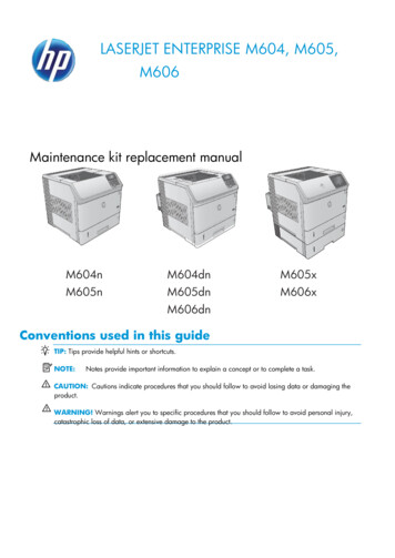
12Step 4: Remove the fuserWARNING! The fuser might be very hot. After turning off the printer power, allow the fuser to cool for atleast 5 minutes before removing it.Squeeze the blue fuser-release tabs (callout 1).Figure 7.Squeeze the blue fuser-release tabsPull the fuser straight back and out of the printer.Figure 8.Remove the fuserPage 16
Step 5: Unpack the replacement fuserUnpack the replacement part from the packaging. /product-recycling.htmlNOTE: HP recommends responsible disposal of the defective part.Figure 9.Recycle and unpackStep 6: Install the fuserPosition the fuser on the printer, and then push it toward the printer to install it.CAUTION: Do not drop or jar the fuser. It can easily be damaged if it is mishandled.TIP: Make sure that the fuser is fully seated into the printer. You should hear both sides snap into place.Figure 10. Install the fuserPage 17
Step 7: Install the rear output binInstall the right hinge pin (callout 1), and then rotate the output bin toward the printer (callout 2).Figure 11.Position the output bin21Make sure that the left hinge pin is installed in the mounting hole.Figure 12.Install left hinge pinPage 18
Step 8: Install the duplex accessory coverNOTE: If the duplex accessory cover was not removed, skip this step and go to Step 9: Install the duplexaccessory on page 19Slide the duplex accessory cover straight into the printer to install it.Figure 13. Install the duplex a
LASERJET ENTERPRISE M604, M605, M606 Maintenance kit replacement manual M604n M604dn M605x M605n M605dn M606x M606dn Conventions used in this guide TIP: Tips provide helpful hints or shortcuts. NOTE: Notes provide important information to explain a concept or to complete a task.