Transcription
PRODUCT MANUALTR200015EB0027 18/9kW Immersion HeaterMulti-Circuit Electric Immersion Kit for Indirect CylindersInstallation,Operation andMaintenance ManualP R AC T I C A L , E F F I C I E N T & S U S TA I N A B L EBUILDING SERVICES SOLUTIONS
WarningsThis manual should be read and understood carefully prior to installation or operation of any part of the EB0027electric immersion heater kit. Failure to read this manual or to follow its printed instructions may lead to personalinjury, damage to the immersion heater and damage to the water heating installation. These instructions shouldbe kept in a safe and accessible place near the water heating unit.The EB0027 immersion heater kit should be stored in a safe place prior to installation to prevent damage to theappliance or heater components. Any unused or discarded components must be disposed of in accordance withthe Waste Electrical and Electronic Equipment Regulations (WEEE) 2013.Copyright 2016 Adveco Limited. All rights reserved.No part of this publication may be copied, reproduced, altered and/or published by any means without the priorwritten approval of Adveco Limited.Any brand names mentioned within this publication are registered trademarks of their respective owners.Adveco Limited reserve the right to modify specifications in this manual at any time and without notification.Adveco Limited accept no liability for third party claims arising from unauthorised use and/or use other than thatas directed within this manual.EB0027 Electric Immersion - Installation and maintenance manual2PRACTICAL, EFFICIENT & SUSTAINABLE BUILDING SERVICES SOLUTIONS
ContentspageProduct Description4User Instructions1.Responsibilities of the User52.Operating Instructions63.User Maintenance Requirements74.Troubleshooting71.Requirements of the Installer/Designer82.Requirements of the Installation83.Location94.Installation Procedure105.Controls116.Technical Details127.Mechanical Connections138.Electrical Connections149.Commissioning Procedure15Maintenance Instructions1.Maintenance Requirements and Check ProceduresContact and Warranty InformationEB0027 Electric Immersion - Installation and maintenance manual16173
Product DescriptionAdveco EB0027 18/9kW Electric Immersion Heater Kit:The EB0027 is a dual-circuit electric immersion heater for use with the ST/IT/ITE/ITS 300-500 andSSB/SSI/SST 500-2500 ranges of direct and indirect cylinders. With two heating circuits, the immersion heatercan supply up to 18kW of electrical output through its primary circuit, with a secondary 9kW circuit thatprovides a variable heating intensity based on periods of demand, for use with differential tariff supplies, or toprovide 50% redundancy backup to the primary immersion heater circuit, depending upon how it is controlled.This ensures a continuous supply of hot water even in the event of a primary heater failure, virtuallyguaranteeing a hot water supply so long as there is power to the building. The 9kW capacity of the secondarycircuit is designed to provide a small quantity of hot water as a temporary solution to a fault with the primarycircuit, enabling a commercial premises to remain open until the duty heater can be reinstated.The immersion heater is sheathed in Nicalloy 825 and is supplied with a stainless steel flange and EPDM gasketsized to fit into the clean-out access of the water cylinders. A pocket-mounted dual control and overheatthermostat is included to be installed in the tank above the element for use with the primary heater, in additionto an internal set of control and overheat thermostats contained within the IP41-rated immersion heaterterminal enclosure for use with the secondary element.Kit Contents:The Adveco EB0027 18/9kW Electric Immersion Heater Kit is supplied with the following contents: 1 E0048: 18/9kW immersion element plus flange.1 E0042.1: EPDM gasket.1 E0010: Pocket mounted combination control and overheat thermostat.1 E0043: Control Thermostat; and 1 E0044: Overheat Cut-Out Thermostat, contained within theimmersion heater terminal housing.Not Included:Additional components required for the installation and operation of this device include: A 3 phase contactor switch.Overcurrent protection (18kW: 30A/phase; 9kW: 16A/phase).An approved isolator.Available Ancillaries:Adveco strive to offer a complete range of control solutions to meet the needs of the end user. The followingancillaries are available and are compatible with the EB0027: E0049: Control panel. Includes auto-changeover functions in the event of faults, for use with electricimmersion heaters. Delivered with pre-wired internal connections, it includes a main isolator, circuitbreakers, and provides power to two electric immersion elements. Includes controls for optional heatreclaim systems and contains BMS fault output relay for on-site notification. Requires a 3-phaseelectrical supply at 32A/phase.EB0028: Kit containing the E0049 control panel plus a GSM modem used to monitor and sendautomatic SMS or email notifications of the fault condition of a connected water heater.EB0027 Electric Immersion - Installation and maintenance manual4PRACTICAL, EFFICIENT & SUSTAINABLE BUILDING SERVICES SOLUTIONS
User Instructions1. Responsibilities of the UserResponsibility is held by the building controller to assess risk to users of their hot water system, to ensure it issafe to use and well maintained. This includes user protection against the dangers of scalding and Legionella. Acomplete list of responsibilities can be found by consulting the following management documents: ACOP L8 (4th edition) HTM 04-01 (part B) Building Regulation Part G WEEE Regulations 2013A guideline to the responsibilities contained within the above documents as relating to the Adveco EB0027 canbe summarised as follows:1. The temperature of hot water in any cylinder should be kept between 60-65 C at all times. Any secondaryreturn system should always return at a minimum temperature of 50 C. Water at the furthest outlets must reach50 C (55 C for healthcare premises) within 60 seconds.2. Any outlets at which water could exceed 55 C must be clearly marked by a warning sign. Thermostatic mixingvalves should be considered, especially where users are considered at high risk. These should be services at leasttwice per year.3. A risk assessment of the hot water installation should be carried out by someone qualified to assess risks andmake recommendations, and should be reviewed regularly. The results of these assessments should beconsidered when determining maintenance regimes.4. The installation must be commissioned by a qualified person before use. See page 14 for furthercommissioning information.Failure to maintain a minimum of annual maintenance may void any and all warranties. Full maintenanceprocedures should be carried out by a recognised technician, and must include a check of the immersion heater,water tanks and descale procedures. Basic maintenance regimes, as determined through risk assessment, shouldbe carried out by the end user as outlined on page 7.EB0027 Electric Immersion - Installation and maintenance manual5
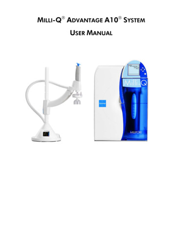
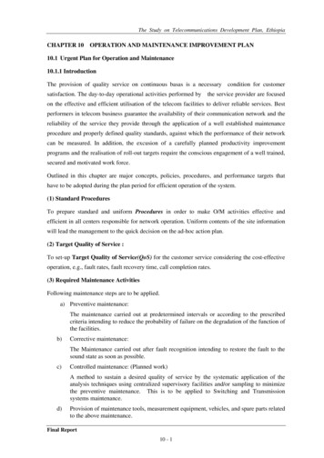
User Instructions2. Operating InstructionsIn installations where the EB0027 is connected to a central control panel or a Building Management System,operation and control of the immersion heater will be governed by those systems.The temperature set-point of the control thermostat should not lie outside of the 60-65 C range to ensure theinstallation meets requirements in regards to Legionella control and safety standards as defined by BuildingRegulations Part G3. This should have been set by the installer and should not need to be altered. Thetemperature set point of the 9kW circuit can be confirmed by checking the commissioning report.Direct temperature control of the 18kW immersion heater can be set by locating the combined control andoverheat thermostat mounted on the side of the cylinder, positioned above the level of the immersion heater.Featured on the front face of the thermostat housing is an adjustable temperature dial for the control thermostatwith a range of 25-65 C. The housing also features a non-self-resetting over-temperature safety cut out, whichcan be accessed for manual reset by unscrewing and removing the small black cover.Control and overheat thermostats for the 9kW element are located within the immersion heater terminalhousing. Ensure that the immersion heater is isolated from the mains electricity before opening the immersionhousing. In the event that the control thermostat requires checking, it is situated in the left side of the terminalabove the element, and has an adjustable dial upon its base. This can be rotated to increase or decrease thetemperature set point of the 9kW circuit. The overheat thermostat (red) is located on the right side of theterminal and features a reset button upon its base.The immersion heater will turn off once the water temperature surrounding the control thermostat sensor in thetank reaches its temperature setting. Should the control thermostat fail, the overheat thermostat will force acut-out of the immersion heater when the water temperature in the vessel reaches the overheat set point. Inthe event of an overheat cut-out, both the E0010 combined thermostat the E0044 immersion housing overheatthermostat must be reset.Putting into use: The immersion element must remain submerged at all times. Ensure that the tank is full prior tooperation. Turn on the isolator and allow a heat up period of 1 hour per 300 litres of water capacity, beforeconfirming that the tank has come up to temperature.Taking out of use: Turn and lock off the isolator. If conditions present a risk of freezing, or if the system will beout of use for an extended period of time, the tank should be drawn down to prevent frost damage or stagnation.Returning to use: Following a short out of use period of more than three days but less than a week, it shouldbe sufficient to turn on the isolator and bring the water tank up to 60 C for at least one hour withthe secondary pump running. Outlets should be flushed before hot water use if there is no secondary return. Ifthe system has been out of use for an extended period, a risk assessment must be carried out whichmay include cleaning and disinfection of the tank in accordance with the site control of Legionella policy.Left: Image displaying the E0010 dual control and overheatthermostat for use with the primary 18kW heating circuit,showing the adjustable control temperature dial and overheatreset cover. This will be mounted on the vessel above andseparate to the immersion heater terminal.EB0027 Electric Immersion - Installation and maintenance manual6PRACTICAL, EFFICIENT & SUSTAINABLE BUILDING SERVICES SOLUTIONS
User Instructions3. User Maintenance RequirementsTo ensure continued reliability and longevity of the immersion heater installation, as well as safety of users,regular maintenance should be carried out by the end user as described here. Isolate the mains electrical connection to the immersion heater terminal. Examine the immersion heater flange connection to the tank for evidence of leaks. Once per year confirm that the thermostats are operating correctly by turning off all other heat sourcesand turning on the duty immersion heater. Allow the system to heat for 1 hour per 300 litres systemcapacity, without hot water draw off, then confirm that the temperature at an outlet without athermostatic mixing valve is between 55-70 C within 60 seconds. Draw off hot water from the tank until the water temperature is 55 C and then repeat the thermostattest using the backup heating element. In the event of any sign of wear, damage or other faults, do not return power to the immersion heaterand instead contact your service technician immediately. Any other maintenance tasks as defined in the risk assessment and ACOP L8, such as periodic flushingof showers and terminal outlets, plus temperature checks of taps with and without thermostatic mixingvalves to assess the hot water system temperature and safety against scalding.4. TroubleshootingIn the event of fault or failure of an immersion heater, notify the installer. All maintenance, replacement andrepair inquiries should be handled by a service technician. All warranty enquiries must be administered byAdveco Ltd.EB0027 Electric Immersion - Installation and maintenance manual7
Installation Instructions1. Requirements of the Installer/DesignerAll installation work for this immersion heater kit must be carried out by an individual with the relevantqualifications and experiences to work with electrical systems and who is registered with an electrical regulatorybody such as NICEIC, and should be compliant to: BS 7671:2008 A3:2015 IET Wiring Regulations 17th Edition. BS EN 806 all parts. BS EN 60335-2-74, IEC 60335-2-74. Building Regulation Part G. Building Standards (Scotland) Regulations. Health and Safety and Work Act 1974. Local Byelaws.And any complementing or superseding documentation.Adveco Limited accept no responsibility for failure to comply with the above or with safe working practices.2. Requirements of the InstallationThe Adveco EB0027 electric immersion heater kit is suitable for installation into systems with pressures up to amaximum of 6 bar and temperatures up to 90 C.Hot water systems pose a potential risk for building occupants with regards to temperature and biologicalhazards. It is the responsibility of the system designer and/or installer to consider the risk to buildinginhabitants/end users of scalding or Legionella and put into place suitable steps to protect the occupants. Thisincludes eliminating system deadlegs and ensuring that the hot water temperature at the furthest outletsreaches at least 50 C (55 C in healthcare premises) within 60 seconds. Guidance and information on theseresponsibilities can be found by referencing the following documents: Building Regulations Part G. Health and Safety at Work Act 1974. BS EN 806. ACOP L8, 2014 (4th edition). HSG0274 (part 2). HTM 04 01 part A and B.It is very important that there is an in-depth handover process to the building controller/user so that theongoing responsibilities of maintenance, risk assessment and system control are fully understood. The systemdesign and intended control methods for temperature and biological hazards within the DHW system andassociated building pipework should be explained to and understood by the building controller/user.EB0027 Electric Immersion - Installation and maintenance manual8PRACTICAL, EFFICIENT & SUSTAINABLE BUILDING SERVICES SOLUTIONS
Installation Instructions3. LocationA suitable clearance of at least 800mm should be present between the immersion heater flange and anyadjacent unit or surface, in order to facilitate access for inspection, maintenance, as well as removal and/orreplacement of the immersion heater. The location of the water heater should provide sufficient lighting formaintenance purposes and be in close proximity to an electrical supply. Suitable drainage should be available sothat any leak from the cylinder will not risk submerging the element terminal or its electrical connections.Immersion port clearancesmm0 um80 inimmmm mu080 inimmST/IT/ITE/ITSEB0027 Electric Immersion - Installation and maintenance manualSSB/SSI/SST9
Installation Instructions4. Installation Procedure Carefully remove all packaging from the immersion heater assembly and inspect the unit for any visualsigns of damage. Ensure that the available electrical supply is three phase, 400V and matches the current rating of theimmersion heater. Drain the vessel according to the standard procedure. Remove the cover, insulation, clean-out flange and gasket. The locations of these are circled in thepictures below. Store these in a safe location in case they are needed in the future. Insert the immersion heater into the opening, ensuring that the gasket and flange are aligned, and boltsecurely to create a tight fit to the vessel. See page 13 for further details. The immersion heater is onlysuitable for horizontal mounting unless specified otherwise. The heater should be orientated so that thehousing panel is facing down, as shown in the terminal diagram on page 13. Fill the system according to the standard procedure. The immersion element should be submerged at alltimes. Ensure that no air pockets remain in the system, and monitor the immersion heater flange connection forleaks. Set the temperature by adjusting the control thermostat dial on each circuit to be between 60-65 C. Ensure that the heater is isolated from the mains electricity supply before wiring. Drill and gland the terminal housing for cable entry points. Wire the terminal connections of the heater as described on page 14. The immersion heater must bewired through a four-pole rotary isolating switch and a contactor, using a cable compliant to BS EN50525. The immersion heater must be earthed. Close and secure the terminal cover. The heater must be isolated from the mains prior to re-opening thecover to make any further adjustment within.ITE Range OnlyST/IT/ITE/ITS RangeEB0027 Electric Immersion - Installation and maintenance manualSSB/SSI/SST Range10PRACTICAL, EFFICIENT & SUSTAINABLE BUILDING SERVICES SOLUTIONS
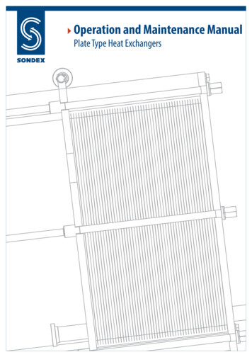
Installation Instructions5. ControlsFor a list of components included with the EB0027, consult the kit contents on page 4.The EB0027 has two heating circuits, however for safety it is recommended that a single isolator is used toisolate both circuits. If two separate supplies are used, a traffolyte label must be permanently fixed to thehousing access door informing maintenance personnel that there are multiple points of isolation.Each heating circuit has a separate set of temperature controls. The primary 18kW heater should be switched onwith a contactor and controlled by an E0010 dual control and overheat thermostat, mounted in the hot watertank separately to and above the location of the immersion heater.The E0010 dual thermostat features a white IP40-rated terminal box, with an adjustable control thermostat dialon its front face for simple temperature adjustment. Its over-temperature cut-out thermostat can be manuallyreset by unscrewing the small black cover on the front face of the E0010 terminal and pressing the buttonpositioned beneath.The secondary 9kW heating circuit should be switched with a contactor and controlled by an adjustable controlthermostat and a fixed overheat cut-out thermostat located in the topmost pair of thermostat pockets situatedinside the immersion heater terminal housing. A further two thermostat pockets are located below the elementswithin the terminal, and for safety reasons should be left empty and unused. Note that the terminal housingshould only be opened after isolation from mains electricity. The control thermostat has an adjustable dial on itsbase which can be rotated to increase or decrease the heating threshold of the electrical element as desired. Theoverheat thermostat features a manual reset button and is factory set to 90 C.Note that for standard installations without an alternative method of legionella protection, the controltemperature on either heating circuit should not be set outside the range of 60-65 C.When connected to a system through a control panel such as the EB0028, or to a building management system(BMS, control options may be handled by those systems directly.Left: Image displaying the E0010 dual control and overheatthermostat for use with the primary 18kW heating circuit, showingthe adjustable control temperature dial and overheat reset cover.This will be mounted on the vessel above and separate to theimmersion heater terminal.Right: Image displaying the head of the temperature control thermostatwith adjustable dial, for use with the secondary 9kW heating circuit,located inside the immersion heater terminal housing. Note that thehousing overheat thermostat (red) is factory set and must noadjustment must be made.EB0027 Electric Immersion - Installation and maintenance manual11
Installation Instructions6. Technical DetailsCapacitySupplyWiringPower (18kW Circuit)Power (9kW Circuit)Intensity (18kW Circuit)Intensity (9kW Circuit)Immersion heater partGasket partCombined thermostatE0010:Housing thermostats:Suitable for use withOptional ancillaries18kW 9kW400V/3ph/50HzL1, L2, L3, N, E26A/phase13A/phase9.2 W/cm213.8W/cm2E0048E0042.1Control range 25-65 COverheat set point 80 CE0043: Control range 30-90 CE0044: Overheat set point 90 CST/IT/ITE/ITS 300-500,SSB/SSI/SST 500-2500E0049 (Auto-changeover control panelwith BMS connections and heat recovery)EB0028 (E0049 SMS fault notification)EB0027 Electric Immersion - Installation and maintenance manual12PRACTICAL, EFFICIENT & SUSTAINABLE BUILDING SERVICES SOLUTIONS
Installation Instructions7. Mechanical ConnectionsThe immersion heater is provided with an EPDM gasket and flange designed to fit directly into theclean-out access of the ST/IT/ITE/ITS 300-500, or SSB/SSI/SST 500-2500 range of vessels. Theimmersion heater can be removed for maintenance, cleaning, repair or replacement. Sealingcompounds should not be applied around the flange, as upon setting they may harden and prevent removalof the heater assembly.To secure the immersion heater into the vessel, insert it into the clean-out access and begin by handtightening the bolts labelled 1 & 2 on the terminal diagram below. The ring gasket can then be positionedcorrectly by resting it upon these two bolts, keeping it in place while the remaining bolts can be handtightened.Once all bolts are loosely screwed in and the immersion heater is positioned correctly, securely tighten all thebolts in a diametrically-opposed fashion to ensure an even stress loading across the immersion heater.Terminal LayoutEB0027 Electric Immersion - Installation and maintenance manual13
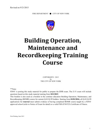
Installation Instructions8. Electrical ConnectionsConsult the terminal diagram displayed on page as 13 as a reference when making three phase electricalconnections.The immersion heater should be connected with fixed wiring and all cables should be correctly sized for theamperage.An element to thermostat direct link wire should not be used.All terminal connections must use crimp ring connections.Wiring DiagramNL1 L2 L3IsolatorFuseOn/Off SwitchE0010 Dual Controland Overheat StatElement SelectionRelay.Contactor SwitchL2L1NL318kWHeater LoadFuseOn/Off SwitchOverheat ThermostatControl ThermostatElement SelectionRelayContactor SwitchL2L1NL39kW HeaterLoadIt is recommended that the base of the terminal should beheld securely (using pliers or another appropriate tool) whentightening or loosening, to ensure that it will not shear off itsconnection if over-tightened.The bottom two thermostat pockets T3 and T4 shouldremain empty and are not to be used for temperature controlof any circuit of the EB0027. The top thermostat pockets T1and T2 should contain one control and one overheat cut-outthermostat as provided with the immersion heater kit. Theseshould be connected for use with the 9kW secondaryheating element.An E0010 dual control and overheat thermostat should bemounted separately on the cylinder above the level of theimmersion heater and connected to the 18kW heatingelement.An all pole isolator with a separation of at least 3mm must beused. Both circuits and all control wiring to thermostats mustbe supplied from one isolator to ensure a single point ofisolation. If multiple isolators or electrical supplies are used,a traffolyte label must be permanently fixed to the housingaccess door informing maintenance personnel that there aremultiple points of isolation.The electrical insulation for each circuit within the immersionheater should be checked before installation. The resistancebetween the live and earth connections within the terminalenclosure should not fall below 1MΩ.This appliance must be earthed. An internal earth connection is containedwithin the terminal box. Note that fuses, contactors, isolators and on/offswitches must be supplied separately.The element selection relay is used to determine which immersion heateris in use depending upon the control methods used with the system.EB0027 Electric Immersion - Installation and maintenance manual14PRACTICAL, EFFICIENT & SUSTAINABLE BUILDING SERVICES SOLUTIONS
Installation Instructions9. Commissioning ProcedureThe Adveco EB0027 electric immersion heater requires commissioning following installation and prior to use bythe end user. This should be carried out by a qualified installer and responsibility is held by them to ensure thatthe system is safe for use. Commissioning should include the following checks:1. Ensure the integrity of all connections, including between the element, flange and water heater.2. Ensure that all electrical connections are tight and that there is a gap of at least 5mm between any bareterminals.3. Ensure that the control temperature setting TSET of the E0010 combined thermostat is within the range of60-65 C.4. Ensure that the temperature setting TSET of the housing control thermostat is within the range of 60-65 C.5. Open the mains water isolation valve and allow the system to fill with water.6. Examine connections for evidence of leaks.7. Measure the current to each element circuit with a clamp ammeter and ensure it is within range of thetechnical details given on page 12.8. Carry out a test of the E0010 combined thermostat temperature control function. Turn off all heat sourcesexcept the 18kW immersion heater, then allow a heat up period of one hour per 300 litres of system watercapacity. Confirm that the temperature reaches and does not exceed the control thermostat setting.9. Carry out a test of the immersion-housing control thermostat. Draw off hot water from the tank until thewater temperature is 55 C and then turn on the 9kW immersion heater alone. Allow a short heat upperiod and then confirm that the tank has come up to but does not exceed the terminal control thermostattemperature setting.10. Test the calibration of the overheat cut-out thermostats.11. Hand over responsibility of the system to the building controller/user. Include a thorough explanation ofthe ongoing responsibilities of maintenance, risk assessment, and system control. Ensure that the buildingcontroller/user fully understands the system design as well as the temperature and biological hazardcontrol methods used in the DHW system and associated building pipework.12. Provide this document to the building controller/user alongside the commissioning report.EB0027 Electric Immersion - Installation and maintenance manual15
Maintenance Instructions1. Maintenance Requirements and Check ProceduresAt minimum, the immersion heater should be serviced annually by a qualified engineer. An initial check should becarried out three months after installation, and the subsequent maintenance demand should be determinedbased on the level of scale build up. The unit must be fully isolated from the mains electricity supply prior to anyinspection or maintenance work being carried out. The maintenance procedure should include at least thefollowing checks: Inspect the mounted element and its physical connection for evidence of any damage or leaks. Ensure that the terminal box is intact and its internal area is dry. Ensure that all electrical connections are secure and show no signs of wear. Drain the tank according to its standard procedure and remove the immersion heater. Check for visualwear on the gasket. Replacement of the gasket should be considered. Examine the heater elements and thermostat pockets for visual signs of wear or build-up of scaledeposits. Descale if necessary. Inspect the tank flange and ensure that the interior of the tank does not contain scale deposits. Cleanout any scale that is found. Re-insert the heater assembly, secure and re-fill the tank according to the standard procedure. Examine the flange connection and ensure no leaks are present. Test the electrical insulation between the live and earth terminals and ensure the resistance is at least1MΩ. Test the amperage through each phase and confirm it is in line with the technical details given on page12. As the element ages it is likely that individual rods will begin to fail. It is only necessary to replacethe immersion heater when it can no longer meet the DHW requirements of the building or the phaseloading becomes too imbalanced. Carry out a test of the E0010 combined thermostat temperature control function. Turn off all heatsources except the 18kW immersion heater, then allow a heat up period of one hour per 300 litres ofsystem water capacity. Confirm that the temperature reaches and does not exceed the controlthermostat setting. Carry out a test of the immersion-housing control thermostat. Draw off hot water from the tank untilthe water temperature is 55 C and then turn on the 9kW immersion heater alone. Allow a short heatup period and then confirm that the tank has come up to but does not exceed the terminal controlthermostat temperature setting.EB0027 Electric Immersion - Installation and maintenance manual16PRACTICAL, EFFICIENT & SUSTAINABLE BUILDING SERVICES SOLUTIONS
Contact and Warranty InformationThe EB0027 Immersion Heater Kit, this manual and all information contained within are supplied by Adveco Ltd.Adveco Ltd.Unit 7&8 Armstrong Mall,Southwood Business Park,Farnborough,Hampshire,GU14 0NRT: 01252 551 540info@adveco.cowww.adveco.coAdveco Ltd. are the point of contact for all warranty claims and queries through the above address.Disposal of any part of the EB0027 Immersion Heater Kit must be carried out in accordance with the WasteElectrical and Electronic Equipment Regulations (WEEE) 2013. The system must be decommissioned by aqualified engineer prior to any equipment disposal.EB0027 Electric Immersion - Installation and maintenance manual17
Adveco also offer the following pro
Adveco EB0027 18/9kW Electric Immersion Heater Kit: The EB0027 is a dual-circuit electric immersion heater for use with the ST/IT/ITE/ITS 300-500 and SSB/SSI/SST 500-2500 ranges of direct and indirect cylinders. With two heating circuits, the immersion heater