Transcription
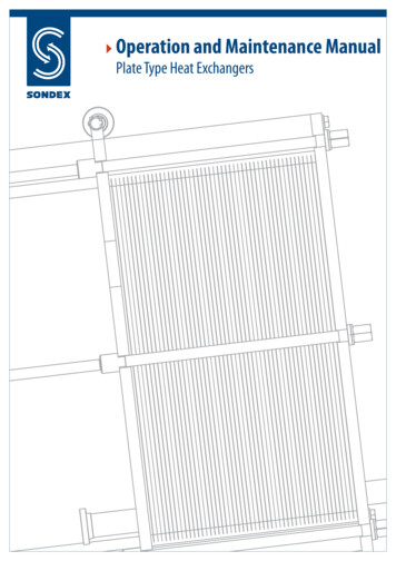
Operation and Maintenance ManualPlate Type Heat Exchangers
Project:Customer:Exchanger type:Serial number:Year:PED category:Approved by:Cat. 1Cat. 2Cat. 3Cat. 4NB number:Remarks:The contents of this publication are based on the latest information available and thematerials that are used at the time of printing. However, because of rapid developments inthis field we cannot be held liable for changes in specifications affecting the contents ofthis publication.COPYRIGHTCopyright SONDEX HOLDING A/S. All rights reserved. No part of this publication may bereproduced or distributed without prior written permission of SONDEX HOLDING A/S.2
CONTENTS1 FOREWORD . . . . . . . . . . . . . . . . . . . . . . . . . . . . . . . . . . . . . . . . . . . . . . . . . . . . . . . . . . . . . . . . . . . . .42 INTRODUCTION . . . . . . . . . . . . . . . . . . . . . . . . . . . . . . . . . . . . . . . . . . . . . . . . . . . . . . . . . . . . . . . . . 43 SAFETY ALERT NOTICES . . . . . . . . . . . . . . . . . . . . . . . . . . . . . . . . . . . . . . . . . . . . . . . . . . . . . . . . . 44 GENERAL . . . . . . . . . . . . . . . . . . . . . . . . . . . . . . . . . . . . . . . . . . . . . . . . . . . . . . . . . . . . . . . . . . . . . . . . 54.1 Identification of the heat exchanger . . . . . . . . . . . . . . . . . . . . . . . . . . . . . . . . . . . . . . . . . 54.2 Correct operation . . . . . . . . . . . . . . . . . . . . . . . . . . . . . . . . . . . . . . . . . . . . . . . . . . . . . . . . . . . 64.3 Cautions . . . . . . . . . . . . . . . . . . . . . . . . . . . . . . . . . . . . . . . . . . . . . . . . . . . . . . . . . . . . . . . . . . . . 64.4 Thermal design . . . . . . . . . . . . . . . . . . . . . . . . . . . . . . . . . . . . . . . . . . . . . . . . . . . . . . . . . . . . . . 75 CONSTRUCTION . . . . . . . . . . . . . . . . . . . . . . . . . . . . . . . . . . . . . . . . . . . . . . . . . . . . . . . . . . . . . . . . . 85.1 Frame . . . . . . . . . . . . . . . . . . . . . . . . . . . . . . . . . . . . . . . . . . . . . . . . . . . . . . . . . . . . . . . . . . . . . . . 85.2 Plates . . . . . . . . . . . . . . . . . . . . . . . . . . . . . . . . . . . . . . . . . . . . . . . . . . . . . . . . . . . . . . . . . . . . . . . 85.3 Gaskets . . . . . . . . . . . . . . . . . . . . . . . . . . . . . . . . . . . . . . . . . . . . . . . . . . . . . . . . . . . . . . . . . . . . . 85.4 Special executions . . . . . . . . . . . . . . . . . . . . . . . . . . . . . . . . . . . . . . . . . . . . . . . . . . . . . . . . . . 95.5 Right/left plates . . . . . . . . . . . . . . . . . . . . . . . . . . . . . . . . . . . . . . . . . . . . . . . . . . . . . . . . . . . . . 96 INSTALLATION . . . . . . . . . . . . . . . . . . . . . . . . . . . . . . . . . . . . . . . . . . . . . . . . . . . . . . . . . . . . . . . . . . . 116.1. Requirements to the installation area . . . . . . . . . . . . . . . . . . . . . . . . . . . . . . . . . . . . . . . . 116.2 Transport, lifting, storage . . . . . . . . . . . . . . . . . . . . . . . . . . . . . . . . . . . . . . . . . . . . . . . . . . . . 136.3 Installing the pipe connections . . . . . . . . . . . . . . . . . . . . . . . . . . . . . . . . . . . . . . . . . . . . . . 137 COMMISSIONING / OPERATION . . . . . . . . . . . . . . . . . . . . . . . . . . . . . . . . . . . . . . . . . . . . . . . . . . 147.1 Commissioning and pre-checks . . . . . . . . . . . . . . . . . . . . . . . . . . . . . . . . . . . . . . . . . . . . . . 147.2 Operation . . . . . . . . . . . . . . . . . . . . . . . . . . . . . . . . . . . . . . . . . . . . . . . . . . . . . . . . . . . . . . . . . . . 147.3 Shut-down for a short period . . . . . . . . . . . . . . . . . . . . . . . . . . . . . . . . . . . . . . . . . . . . . . . . 157.4 Shut-down for a long period . . . . . . . . . . . . . . . . . . . . . . . . . . . . . . . . . . . . . . . . . . . . . . . . . 158 MAINTENANCE . . . . . . . . . . . . . . . . . . . . . . . . . . . . . . . . . . . . . . . . . . . . . . . . . . . . . . . . . . . . . . . . . . 168.1 Clean in place (CIP) . . . . . . . . . . . . . . . . . . . . . . . . . . . . . . . . . . . . . . . . . . . . . . . . . . . . . . . . . . 168.2 Some cleaning detergents . . . . . . . . . . . . . . . . . . . . . . . . . . . . . . . . . . . . . . . . . . . . . . . . . . . 168.3 Opening the heat exchanger . . . . . . . . . . . . . . . . . . . . . . . . . . . . . . . . . . . . . . . . . . . . . . . . 178.4 Cleaning the plates . . . . . . . . . . . . . . . . . . . . . . . . . . . . . . . . . . . . . . . . . . . . . . . . . . . . . . . . . . 188.5 Plate replacement . . . . . . . . . . . . . . . . . . . . . . . . . . . . . . . . . . . . . . . . . . . . . . . . . . . . . . . . . . . 198.6 Gasket replacement . . . . . . . . . . . . . . . . . . . . . . . . . . . . . . . . . . . . . . . . . . . . . . . . . . . . . . . . . 198.7 Tightening of the plate pack and pressure testing . . . . . . . . . . . . . . . . . . . . . . . . . . . . 208.8 Maintenance of the heat exchanger . . . . . . . . . . . . . . . . . . . . . . . . . . . . . . . . . . . . . . . . . 219 PROBLEM SOLVING . . . . . . . . . . . . . . . . . . . . . . . . . . . . . . . . . . . . . . . . . . . . . . . . . . . . . . . . . . . . . . 2210 AFTER SALES SERVICE . . . . . . . . . . . . . . . . . . . . . . . . . . . . . . . . . . . . . . . . . . . . . . . . . . . . . . . . . . . 2410.1 Ordering parts . . . . . . . . . . . . . . . . . . . . . . . . . . . . . . . . . . . . . . . . . . . . . . . . . . . . . . . . . . . . . 2410.2 Modifications to the heat exchanger . . . . . . . . . . . . . . . . . . . . . . . . . . . . . . . . . . . . . . . . 243
1 FOREWORDThis manual is a guide for installation, commissioning and maintenance of plate type heatexchangers supplied by SONDEX.It is meant for those who are responsible for the installation, the use and maintenance ofthe heat exchangers. We recommend that you read this manual carefully beforecommencing any work.2 INTRODUCTIONThis manual is applicable for all heat exchangers produced and supplied by SONDEX.SONDEX can not be held responsible or liable for damage as a result of incorrectinstallation, use and / or maintenance of SONDEX plate type heat exchanger as wellas not complying with the instructions in this manual.Please note that our plate type heat exchangers are specially designed and built forthe operating conditions (pressures, temperatures, capacities and type of fluids)provided by the customer. Sudden pressure peaks beyond the normal operatingpressure (or pressure surges) which can occur during starting up or stopping of thesystem can severely damage the heat exchanger and should be prevented. SONDEXcan not be held responsible for any damage as a result of any operation deviatingfrom the original design conditions.If you wish to alter the design conditions, please contact us refer page 24. You may onlycommission the heat exchanger under the modified conditions after inspection and writtenapproval by SONDEX. Also the name plate on the heat exchanger will be adapted.3 SAFETY ALERT NOTICESSafety Alert NoticeFollowing must be respected by installing/running/servicing plate heat exchangers:Keeping current local safety regulations.Before any work begins ensure that the exchangers are pressureless and cooled till under40ºC.Use gloves for preventing any injury from sharp edges when handling plates.In all cases ensure that all laws and regulations are strictly kept concerning human/environment protection.YELLOW TRIANGLERefer to applicable SAFETY ALERT notices within the manual!All SAFETY ALERT notices are applicable to personal injury and identified by the followingsymbol.4
4 GENERAL4.1 Identification of the heat exchangerAll plate type heat exchangers supplied by SONDEX are provided with a name plate.On this plate the following details are specified: type of heat exchangeryear of manufacturemanufacturing numbernominal capacity in kWtransmission area in m2max. working pressure in bartest pressure in barmax. working temperature in Cmin. assembling measure in mmELPMAXEFIG 15
4.2 Correct operationThis user manual provides information and instructions for correct and safe operation ofthe unit. Many accidents are caused by incorrect use!It is essential that you study the instructions carefully, and above all, ensure the availabilityto those who install, maintain and operate the heat exchanger on a daily basis. This manualis of no value if it is not available at the time when your staff needs it.If a problem occurs with your SONDEX Heat Exchanger which is beyond the scope of thismanual, do not hesitate to contact us. The installation should not be put into operationbefore all indistinctnesses have been solved!To avoid injuries and damages, follow the instructions and local applicable safety regulations.Also take the necessary protective measures, depending on the nature of your process orcircumstances related to it, at your plant.Please note that our plate type heat exchangers are especially designed and built for theoperating conditions (pressures, temperatures, capacities and type of fluids) provided bythe customer. Sudden pressure peaks beyond the normal operating pressure (or pressuresurges) which can occur during starting up or stopping of the system can severely damagethe heat exchanger and should be prevented.SONDEX can not be held responsible for any damage as a result of any operation deviatingfrom the original design conditions.If you wish to alter the design conditions, please contact us. You may only commission theheat exchanger under the modified conditions after inspection and written approval bySONDEX. Also the name plate on the heat exchanger will be adapted.4.3 PrecautionsAll potential personal injury hazards are identified by safety alert symbol.Bodily harm can be caused by: burning as a result of touching the heat exchanger or other parts of the installation; the uncontrolled release of pressurized media with which the danger of burning andother injuries is present; contact with chemicals; touching sharp edges of the installation.Damage to equipment can be caused by: external forces; corrosion; chemical action; erosion; material exhaustion; water hammer; thermal and / or mechanical shock freezing; wrong transport / lifting.6
Even after stopping the installation some parts of it can still be hot!The heat exchanger may only be used with the fluids specified on the datasheet.The hot medium may not flow through the exchanger without the cold medium flowingthrough. This is to prevent damage to the exchanger.In case the cold medium is present but does not flow while the hot medium is flowingthrough, the cold medium will start boiling and the exchanger will be damaged.Sudden pressure and temperature changes should be prevented.When a heat exchanger (filled with water or a water mixture) which is not in operation isexposed to temperatures below zero, the plates can become deformed.If a danger of frost occurs, the heat exchanger should be drained completely.Demountable plate heat exchangers can always leak. We advise you to take this intoaccount while installing. Preferably you should install a drip tray underneath the heatexchanger to prevent leakages onto the floor and/or harm to electrical equipment.(Short circuit/moisture damage).If the heat exchanger is being used with temperatures above 60º C or with aggressive fluids,we advise you cover the heat exchanger with a screen plate to prevent the risk of touching.If welding activities have to be carried out near the heat exchanger, never use the heatexchanger for earthing the construction work.Electrical currents can cause severe damage to both plate and gasket.If you have to weld, dismantle the connecting flanges and isolate the heat exchanger fromthe system.4.4 Thermal DesignSondex plate type heat exchangers are designed and calculated according to the newesttechnology.If performance test has to be carried out, the exchanger must be totally clean.In the Sondex data sheet the nominal capacity and pressure losses are mentioned.The pressure loss can deviate up to 15 % from the data in the data sheet depending onplate thickness, the plate material and the difference in the two working pressures.7
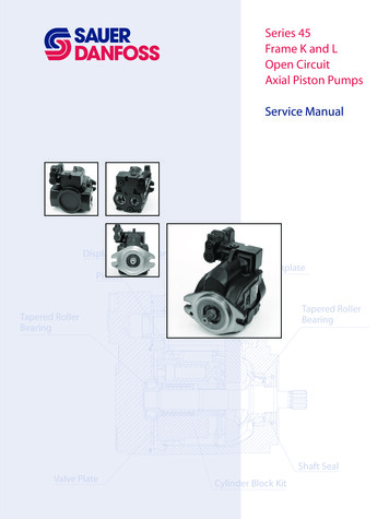
5 CONSTRUCTIONUpper barColumnFollowerPlate packageHeadLower barTie bolts5.1 FrameThe heat exchanger consists of a frame plate (head), a pressure plate (follower), a carryingbar, a lower bar and a column. Tie (clamping) bolts are used to press the plate packagetogether. The size and number is depending on the type of heat exchanger.5.2 PlatesThe plate package consists of plates with a groove along the rim of the plate andaround the ports. The number of plates is, as well as size and dimension, dependanton the thermal output required. Depending on the application stainless steel ortitanium plates might be used5.3 GasketsThe groove provided in the plates holds the special gasket. The purpose of thisgasket is to prevent intermixing of the media and leakage to the outside.The gaskets are selected to suit the actual combination of temperature, chemicalresistance and possible other conditions to be considered.They can be supplied in Viton, Nitrile or EPDM.8
The following types of packings are being used in our plate type heat exchangers: Glue gaskets "Sonder Snap" "Sonder Lock" gaskets (new generation of gaskets) "Hang-on" gaskets"Sonder Snap" gasket"Sonder Lock" gasket"Hang-on" gasket5.4 Special applicationsIf the plate heat exchanger works with several fluids at the same time, it can be necessary toinsert intermediate frames.The intermediate frames are equipped with corner blocks, forming connections be-tweenthe different sections. Two connections can be placed in the same corner block, havingconnection to two different sections in the plate heat exchanger.For the exact application of your plate type heatexchanger please check the documentationwhich was supplied with the heat exchanger.5.5 Right/left platesThe SONDEX plates are designed in such a way that they can be usedboth as right and as left plates. The plates just have to beturned 180º. ( Excepted are types S1, S53 and SF52, which are “diagonal”plates. Here right and left plates are different ).Right and left plates:On a right plate the flow runs from hole 2 to hole 3 or reverse from hole 3to hole 2.On a left plate the flow runs from hole 1 to hole 4 or reverse from hole 4to hole 1.The opening of the corner holes are described in a “plate code index”. Forinstance 1234 means that all corner holes are open.Every plate can be identified by the gasket configuration, the plate codeindex and thermal short or thermal long execution.9
PLATE TYPES:Start plate with gasketLeft hand flow plate with gasketRight hand flow plate with gasketEnd plate with gasketThermal long plateThermal short plate10
6 INSTALLATIONB6.1 Requirements to the installation areaIt is very important that enough space around the plate typeheat exchanger is kept free for servicing of the unit (renewal ofplates, tightening of the plate package).As a rule the free space around the unit should be1, 5 to 2 x the width of the unit.6.2 Transport, lifting and storageWARNING: To prevent personal injury always use appropriate hoisting equipment. If you areto lift the heat exchanger itself, straps should be used. They should be placed as shown on thepicture.11
Lifting:Usually the heat exchanger will be supplied horizontally on a pallet.The back side of the head will then be tightened to the pallet. This allows youto transport the unit by means of a fork lift truck.Rising of the unit: Remove all tightening elements from the pallet; Place straps around one bolt on each side as shown on the picture.Never use steel cables or chains! Lift the heat exchanger from the pallet; Lower the heat exchanger slowly to vertical and on it’s feet and place it init’s end position on the floor. Remove the straps and tighten the heat exchanger to the floor.Never lift the heat exchanger by using the connections or studsaround them!Attention:ALWAYS:Use the lifting eyes (if fitted)Lift the top side of the headAttach the straps to the bolts close to the headNEVER:Lift using the connectionsLift the followerLift using an intermediate plateLift with a strap attached close to the followerStorage:Should it be necessary to store the heat exchanger for a longer period (1 month or more),certain precautions should be taken in order to prevent unnecessary damage to theequipment.Preferably the heat exchanger should be stored inside in a room with a temperature around15 to 20 ºC and a humidity of max. 70%.If this is not possible, place the heat exchanger in a wooden box which is provided with alining on the inside against penetration of moisture.There should absolutely not be any ozone producing equipment in the room, like electricmotors or arc-welding equipment, since ozone destroys many rubber materials. Also do notstore organic solvents or acids in the room and avoid heat or ultraviolet radiation.12
6.3 Installing the pipe connectionsDepending on the type the SONDEX plate type heat exchanger will be provided withflanges, couplings, threaded pipes, etc.When connecting the pipe system to the heat exchanger make sure that no stress orstrain is imposed, by the pipe system, on to the heat exchanger!We advise you of the following: Heavy pipe work needs to be supported. This will prevent heavy forces on the heatexchanger. Always install flexible connections on the follower to prevent vibrations on the heatexchanger. These flexible connections also prevent expansion of the pipe work, caused bytemperature influence, onto the heat exchanger. These flexible connections need to be fitted in a longitudinal direction to the plate package. The pipe work needs to be thoroughly cleaned and flushed before connecting up to theheat exchanger. Always install vents on both sides of the heat exchanger.Note: For proper venting the vents should be fitted on the highest point in the direction ofthe flow of the medium (preferably on an air vessel).To enable the heat exchanger to be opened when necessary shut off valves should beprovided in all connections!Make sure that the pipe work, connected to the heat exchanger, is secured againstpressure peaks / surges and temperature shocks!Threaded pipe connections:If a plate type heat exchanger is provided with threaded pipe connections, make sure thatthese connections do not rotate when fitting to the pipe work. It could damage the gasketon the start plate. You need to make “counterhold” on the connection!Flange connections:If the connection is rubber lined, the liner will act as the flange gasket.Bolt the connecting flange directly to the endplate using the drilled and tapped holesprovided. Tighten the bolts evenly – do not over-tighten as this could strip the threads cutinto the frame plate.If loose backing flanges are fitted to the heat exchanger a suitable gasket is required to sealthe flange.Unless otherwise stated, the liquid circuits should be connected to flow in reverse directionsthrough the exchanger (counter-current). Refer to the contract drawing or quotation detailsif the connections are not marked.13
7 COMMISSIONING7.1 Commissioning and pre-checksCommissioning may only be done by staff specially trained for the job or by SONDEXcommissioning engineers.Control, maintenance and repair of the installation may only be done by authorized, trainedand properly instructed staff.Maintenance and cleaning may only be done with a heat exchanger cooled to under 40 Cand shut down!Check if all connections are fitted correctly (see also 6.3).Filtration:The media flowing through the heat exchanger should not contain particles larger than 0,5mm diameter/length. If necessary ”inline” filters should be fitted.Check the pressures and temperatures of the media and make sure that these are not morethan the values specified on the name plate.It is essential that the heat exchanger is not subjected to thermal or mechanical shockas this could lead to premature gasket failure7.2 OperationStart cold circuit first, then the hot circuit.Fully vent the system; Close shut off valve fitted between pump and exchanger; Fully open valve fitted into return line from the exchanger; Start the circulation pump normally placed by the inlet; Gradually open closed shut off valve between pump and exchanger; Vent system again if necessary.Repeat the above for the secondary circuit.14
When using steam as one of the media:Use slow acting steam control valves and open slowly shut off valves!Before start up: Ensure that the steam control valve is fully closed Ensure that the heat exchanger is fully drained of condensate Start cold circuit first, then the steam side Open steam control valve slowly – this prevents water hammer of any condensate in thesteam line and reduces the pressure / thermal shock to the exchanger Ensure that the steam trap is correctly sized to allow full condensate discharge – thisprevents water clogging inside the exchangerCheck for proper operation: Check for pressure pulses in the system caused by the pumps or control valves. If found,stop operation and rectify. Continuous pressure pulses will result in fatigue failure of theplates. Visually check the unit for leakages. Check that all vents are closed to prevent air being sucked into the system.When in operation, the conditions should not be changed. The max. conditionsspecified on the name plate should not be exceeded.7.3 Shut-down for a short periodIf the plate type heat exchanger has to be shut down for a short period, pleasefollow the following procedure: Slowly close the control valve in the hot circuit whilst maintaining the full flowin the cold circuit; Switch off the hot circuit pump; Cool down the heat exchanger to under 40 C; Slowly close the control valve in the cold circuit; Switch off the cold circuit pump; Close all remaining shut off valves.7.4 Shut-down for a long periodIf the unit is to be taken off line for an extended period of time then the followingprocedure should be followed:Point 7.3 must be followed, then: Allow unit to cool down; Drain all circuits; Lubricate threads on the tie (clamping) bolts; Loosen tie clamping bolts until the plate pack is “loosened” (max. "A" size 10%). The tie bolts should not be removed or loosened to such an extent that dirt is allowed toenter in-between the plates. We recommend that a warning notice is attached to theexchanger to remind personnel that the tie clamping bolts need adjustment before theunit can be put back into service. Cover the plate pack with black plastic to exclude any sunlight.Please also see chapter 6.2 - Storage15
8 MAINTENANCE8.1 Clean in place (CIP)CIP cleaning (clean in place by circulating cleaning detergents)To use CIP cleaning, it is a condition that the scaling on the plates is soluble. All materials inthe whole circulation system of course have to be resistant to the cleaning detergent.We advise you to ask for a confirmation from the supplier of the cleaning detergentthat it will not damage the materials in the heat exchanger.If the solution requires recirculation, select a flow that is as high as possible, andcertainly no less than the service or product flows.Follow the instructions as given by the detergent supplier / cleaning specialist.We suggest that for recirculated cleaning detergent methods, the fluid should be pumpedthrough the exchanger for no less than 30 minutes.RinsingAfter using any type of cleaning agent, always rinse thoroughly with fresh water.If cleaning in place then circulate fresh water for at least 10 minutes.8.2 Some Cleaning DetergentsOil and grease can be removed with a water emulsifying oil solvent i.e. BP system.Organic and grease cover can be removed with sodium hydroxide (NaOH) maximumconcentration 1,5% - max. temp. 85 ºC.Mixture for 1,5% concentration 5 ltr. 30% NaOH per 100 ltr. water.Stone and limestone can be removed with nitric acid (HNO3) - max. concentration 1,5 % max. temp. 65 ºC.Mixture for 1,5% concentration 2.4 ltr. HNO3 62% per 100 ltr. water.Nitric acid also has an affective build up effect on the passivation film of stainless steel!CAUTION:Nitric acid and Sodium Hydroxide may cause injury to exposed skin, eyes, and mucousmembranes. Use of protective eyewear and gloves is strongly recommended.16
8.3 Opening the plate heat exchangerWhen opening and assembling the heat exchanger observe the following: Measure and note the actual "A" size; Use the correct tools and lubricant; Shut down the heat exchanger as described under 7.3; Make sure the heat exchanger cools down ( 40 ºC); Ensure there is no pressure on any part of the unit; Clean the tie (clamping) bolts and grease the threads; Loosen the tie clamping bolts equally in the correct order (fig. 10) i.e. thatthe follower shall have a parallel opening motion; Pull the follower back towards the column; Remove the plates without damaging the gaskets.CAUTION:Ensure unit is depressurized and drained of hot and/or aggressive product before unitis opened to prevent personal injury.CAUTION:Sharp edges. When handling plates, gloves should be worn.Recommendation:Mark the plate package before opening.You could mark the plate package with a diagonal line on the outside fig 10a, or numberthe plates in sequence.223322Fig. 1017Fig. 10a
8.4 Cleaning the platesCAUTION:Always wear gloves and eye goggles when using cleaning detergents.Use nylon or other types of “soft” scrubbing brushes with detergent.Never use a metal brush, steel wool or sand/glass paper.This will damage the passivation film of the plates.Use Acetone or other types of solvents which do not contain chlorine to remove old gasketglue. Alternatively use a ”lowtemp.” gas flame softly heating the reverse side of the plate.Do not use any other type of gas which may produce a “harder” flame.Remember ventilation. Boiling water can be used with some success.Consult a cleaning specialist for a suitable choice of detergent. Ensure that all detergentsused are compatible with the plate and gasket material before use.In case plates are removed for manual cleaning, make sure they are re-fitted in the sameorder.Always remove plates one by one and number them!A high pressure cleaner can be used but with absolute care and never add abrasives.If the scaling or organic layer is thick the plates can be put in a barrel with qualifiedcleaning material.Before fitting chemical cleaned plates they need to be thoroughly rinsed with freshwater!Important:Cleaning is an important part, influencing the effectiveness of the plate heat exchanger.Insufficient cleaning can have the following results: too low circulation flow; insufficient thermal output; life time of the heat exchanger will be shortened.If a plate has to be renewed because of serious damage, the plates next to this platenormally need to be replaced.18
8.5 Plate replacementThe plates must be clean, dry and free from oil or grease. If there are any oil remains on thegaskets, or on the gasket seating area, then there is a high risk that the plates or gasketsshall slip out of place when the unit is being tightened. If the gaskets are contaminatedwith dirt or grit, then these could cause leakage. make sure that all seating areas are flat, clean and undamaged. always use new gaskets.CorrectWrongFit the plates according to the Plate Sequence Sheet – ensure all gaskets facetowards the fixed frame plate (head).Alternate between left and right handed plates – if the plate edges form aregular honeycomb pattern, the left / right hand sequence is correct, seefig.11.8.6. Gasket replacementFig 11Glue free gasketsThis type of gasket (“Hang-on”) and “Sonder Lock” (new generation of gluefree gasket) require no adhesive. They are located by pushing the gasket fullydown into the gasket groove or fastened by special devices. Make sure grooveand gasket are clean!Glue type gasketsThe surfaces need to be clean and free of oil.Only use chloride free glues like Pliobond 20 or 30, Bostic 1782,3M EC 1099 and Bond Spray 77.Follow the instructions of the manufacturer; these will be printed on the coverof the glue.CAUTION:When using commercial solvents and adhesives, follow the manufacturersrecommendations carefully, as many of these materials are hazardous.19
Ring GasketsThe ring gaskets are used in connection with intermediate frames, by connections in thefollower and by ”SW” (Semi Welded) types.It can be necessary to use a little glue for positioning the ring gasket during assembly ofthe heat exchanger.Rubber LinersThere is one type of rubber liners for connections in the head an another type of rubberliners for connections in the follower.8.7 Assembling of the plate package and pressure testing Lightly oil the tie (clamping) bolt threads. Do not allow oil or grease onto the gaskets orthe gasket seating faces on the back of the plates. Wet or contaminated plates canbecome misaligned during tightening. In this case, dismantle, clean, and dry all areas incontact with the gaskets. Evenly tighten all bolts in the correct order (refer page 17 fig. 10).We advise the use of ratchet spanners. Ensure clamping is as uniform as possible, thus keeping the frames and plates parallelthroughout the operation. Avoid skewing the frame plates by more than 5 mm. Tightening is complete when the distance between the inside faces of both frame platesequals the “A” distance as shown on the contract drawing, see fig. 12. This tightening distance can also be calculated using the following formula: Assembly distance No. of plates x (plate thickness coefficient)The coefficients can vary depending on the model type, but is often 0,1 mm. Finally check that all tie (clamping) bolts are in tension and clean any spilt oil off the head,follower and plates. On completion the uni
This manual is a guide for installation, commissioning and maintenance of plate type heat exchangers supplied by SONDEX. It is meant for those who are responsible for the installation, the use and maintenance of the heat exchangers. We recommend that you read this manual carefully before commencing any work. 1 FOREWORD 2 INTRODUCTION