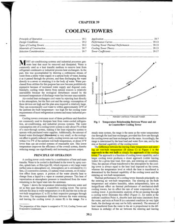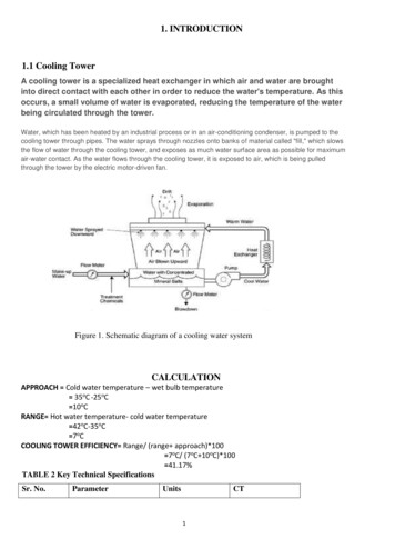
Transcription
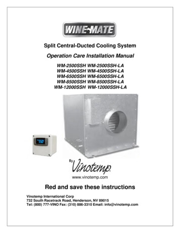
Split Central-Ducted Cooling SystemOperation Care Installation ManualWM-2500SSH WM-2500SSH-LAWM-4500SSH WM-4500SSH-LAWM-6500SSH WM-6500SSH-LAWM-8500SSH WM-8500SSH-LAWM-12000SSH WM-12000SSH-LAwww.vinotemp.comRed and save these instructionsVinotemp International Corp732 South Racetrack Road, Henderson, NV 89015Tel: (800) 777-VINO Fax: (310) 886-3310 Email: info@vinotemp.com
Important Safety InformationWARNINGTo avoid the risk of electrical shock, property damage, personal injury, or death: The power cord must be plugged into a 3-prong grounding type wallreceptacle, grounded in accordance with the National Electrical Code,ANSI/NFPA 70 – latest edition and local codes and ordinances.It is the personal responsibility of the consumer to have a proper 3-prong wallreceptacle installed by a qualified electrician.DO NOT, UNDER ANY CIRCUMSTANCES, REMOVE THE POWER CORDGROUNDING PRONG.A separate adequately fused and grounded circuit should be available for thisappliance.Do not remove any grounding wires from individual components while servicingunless the component is to be removed and replaced. It is extremely importantto replace all grounding wires when components are replaced.WARNING ELECTRICAL SHOCK HAZARDDisconnect electrical supply from appliance before servicing. Replace all panels before operating. Failure to do so could result in death or electrical shock.-1-
Table of ContentsCellar Construction Guide3Features & Specifications4Temperature & Humidity6Care Guide10User’ Troubleshooting11Installer’s Instructions14Electrical --------------------------------- 30-2-
Cellar Construction GuideThis is only a guide and shall be considered as the minimum requirements.All interior walls, ceilings and floors shall have a vapor barrier and a minimum ofR13 insulation. All exterior walls and ceiling shall have a vapor barrier and aminimum of R19 insulation. The vapor barrier shall be installed on the warm sideof insulation. All joints, door frames, electrical outlets or switches and any pipesor vents that go through the cellar shall be sealed to prevent air and moistureleaking into the cellar. Concrete, rock, and brick are not insulations or vaporbarriers. Doors shall be of a minimum size, insulated to at least R13 and tightlysealed with high quality weather stripping. Be sure to seal the bottom of the doorand fill gap between the door’s frame and wall before installing the cap molding.In order to maintain 55 F in the wine cellar, the ambient temperature surroundingthe cellar shall not exceed the temperature of the cellar by morethan 25 F.No cellar walls shall receive direct sun or strong wind.Lighting shall be of low wattage, with a timer to insure lights are not left on whenthe cellar is not occupied.The cooling system will not be able to maintain the proper temperature if freshmoisture-laden air is constantly being introduced to the cellar. Symptoms of thiscondition are; cooling unit runs all the time with only a slight reduction intemperature and/or water overflows from the cooling unit. Because of thetemperature difference between the inside and outside, very small cracks canallow large amounts of outside air to enter into the cellar. Please be aware thatmoisture can pass through solid concrete, paint and wood. Often a newlyconstructed cellar contains fresh wood, paint, concrete and other buildingmaterials. These materials contain large amounts of moisture. When placed intooperation in this type of environment, the system will work harder to remove thisextra moisture resulting in increased “run” time.-3-
Features and Specifications WINE MATE split central-ducted cooling systems WM-2500 12000SSH and WM2500 12000SSH-LA are designed to provide a cold environment between 50 65 F witha humidity range within 50 70% RH for a properly insulated wine cellar. These temperature and humidity ranges are optimized for long term storageof winelike that in natural caves. SSH evaporator units are designed to provide chilled air to a wine cellar throughinsulated ducts and they can be installed up to 25 ft away from the cellar to reduce noise.It also provides better installation flexibility. SSH cooling systems consist of a remote condensing unit and an evaporator unit andthey are connected by a liquid line and an insulated suction line. SSH condensing units can be located away from the wine cellars up to 75 ftso thatnoise and compressor vibration are isolated.Fig. 1 SSH Split Central Ducted Cooling System-4-
CAUTIONNOTEIf the condensing unit will operate below 50 F, install a lowambient condition kit.The cooling capacity is determined under 55 F cellartemperature, 75 F cellar ambient temperature and 90 Fcondensing unit ambient temperature, with R13 interior and R19exterior insulations. Higher ambient temperatures or lowerinsulations will cause reducing capacity and the cellartemperature may not be maintained at 55 F.The specifications are listed as follows:Model No.Capacity (Btu/h) / Airflow(CFM)Max Cellar Size (cuft)2500 / 2202504500 / 38010006500 / 49015008500 / 750200012000 / 8103300WM-2500SSHWM-2500SSHLAWM4500SSH WM4500SSH-LAWM6500SSH WM6500SSH-LAWM8500SSH WM8500SSH-LAWM12000SSH WM12000SSH-LANOTE“LA” refers the unit equipped with a low ambient kit.For further info, see Fig. 3 7.-5-
Temperature and Humidity1. The controllerFig. 2 TEMPERATURE CONTROLLER1) KeysSET: To display set-point; in programming mode it selects a parameter or confirmsan operation.: To start a manual defrost.: To see the maximum stored temperature; in programming mode it browsesthe parameter codes or increases the displayed value.: To see the minimum stored temperature; in programming mode it browsesthe parameter codes or decreases the displayed value.: To turn on/off the power to the unit. : To lock/unlock the keypad.SET : To enter in the programming mode.SET : To return to the temperature display.2) Lock and unlock the keysTo lock the keys, press up down keys until POF is displayed; to unlock thekeys, press up down keys. until PON is displayed.3) DisplayDuring normal operating conditions, the display shows the value measured bythe air temperature probe. In case of active alarm, the temperature flashesalternately to the code alarm. The LED functions are listed as essor enabledAnti-short cycle enabledDefrost enabledFan enabledFan delay after defrostenabledAlarm occurringTemperature measuringunitProgramming modeONONFlashing-6-
4) Alarm SignalsThe alarm codes are described as follows.MESSAGEP1CAUSETemperature probefaultyHAHigh temperaturealarmLALow temperaturealarmExternal alarmCAFUNCTIONCompressor switching to Con and CoFProbe temperature ALU higher than thesetting temperature; Outputs unchangedProbe temperature ALL lower than thesetting temperature; Outputs unchangedAll outputs offProbe alarms P1”, start a few seconds after the fault in the related probe; theyautomatically stop a few seconds after the probe restarts normal operation.Checkconnections before replacing the probe. Temperature alarms “HA”, “LA”automatically stops as soon as the temperature returns to normal value. Alarm“CA” (with i1F PAL) recovers only by switching off and on the instrument.2. Temperature Setting Set the temperature at 55 F for the optimum aging of wineOn initial start-up, the time required to reach the desired temperature willvary, depending on the quantity of bottles, temperature setting andsurroundingtemperature.Allow 24 hours to stabilize the temperature for each new temperature settingoperation3. How to see temperature set-point1) Press and immediately release the SET key, the display will show the set-pointvalue.2) Press again and immediately release the SET key to display the probe value.4. How to change the set-point1) Press and hold the SET key until the “ C” or “ F” LED starts flashing and theset-point is displayed.2) Press the up/down keys /to change the set-point value within 10 sec.3) Press the SET key again to store the new set-point value.NOTEThe unit turns on at set-point Set plus regulation differential Hy afteranti-short cycle AC has elapsed; the unit turns off at set-point Set.-7-
5. Manual DefrostPress and hold the defroston.key until defrost starts. The defrost indicator will be6. Parameter Programming1) Press and hold the SET keys until the “ C” or “ F” LED starts flashing,then release the keys.2) Press and hold again the SET keys until the Pr2 label is displayed, thenrelease the keys. The first parameter Hy will be displayed.3) Press up/down keys / to scroll to the required parameter within 10 sec.4) Press the “SET” key to display its value.5) Use up/down keysto change its value within 10 sec.6) Press “SET” to store the new value and the display will flash 3 times.7) To exit: Press SET or wait 15sec without pressing a AULT VALUEset-point( )temperature regulation differential ( )anti-short cycle delay (min)compress on with probe faulty (min)compress off with probe faulty (min)temperature unit ( F/ C)display resolutiontemperature display delay (min)probe calibration ( )minimum set-point ( )maximum set-point ( )defrost interval time (hour)defrost endurance time (min)temperature alarm typehigh temperature alarm ( )low temperature alarm ( )alarm recovery differential ( )temperature alarm delay (min)temperature alarm delay on startup(hr)heater set-point ( )heater regulation differential ( )fan actionfan operating mode55fan on with compressor off (min)fan off with compressor off (min)410 (hidden)1530F: Fahrenheitin: integer1050651230rE: relative to set-point101056023404StdC-n: on with compressor & off duringdefrost015Depending on the controller, not all parameters are available.-8-
7. How to calibrate the air probeIf the actual cellar temperature differs from the setting temperature, set parameterot actual cellar temperature minus set-point.8. How to adjust defrost settingsIn case there is excessive frost, the parameters FnC C-y, idF 4 and MdF 20 can be used to avoid frost.9. How to adjust the humidityThe parameter Fon is used to adjust the humidity in the wine cellar. Higher Fonresults in higher relative humidity. Use a separate hygrometer to monitor thehumidity.10. How to set alarm call1) Speech notice will be sent to your phones when the cellar temperature is ALUhigher or ALL lower than the set-point Set.2) In order to test the call function, set parameters Ald 0 and dAO 0. Aftertesting, set Ald 60 and dAO 23.11. How to set cellar heaterThe heater turns on at SAA minus Shy; the heater turns off at SAA.NOTEUse a forced air heater to warm up the wine cellar.If there is a thermostat on the heater, bypass it or set thethermostat at the highest level.If the heater runs more than 10 A current, use a 120VAC coilcontactor.-9-
Care GuideIn general, always unplug system or disconnect power while doing care.1. Condenser Coil Cleaning Clean the condenser coil regularly. Coil may need to be cleaned at leastevery 6 months. Use a vacuum cleaner with an extended attachment to clean the coil when itis dusty or dirty.2. Condensate Removing Remove the excessive condensate if it is accumulated in the wine cellarunder high humidity conditions.-10-
User’s TroubleshootingThis Troubleshooting Chart is not prepared to replace the training required for aprofessional refrigeration service person, not is it comprehensive.Complaint1. Unit not running2. Unit not starting, buttemperaturerising high3. Temperaturefluctuating4. Temperaturehigh, unitstopping andstartingnormally5. Temperaturehigh, unitstopping andstarting withshort runningtime6. Temperaturehigh or notcooling andrunningcontinuallya.b.c.d.e.f.g.h.i.a.Possible CausesPower cord not pluggedNo power from supplyIncorrect or loose wiringsLow voltageSetting higher thanambienttemperatureWaiting for cut-inDefrost light blinkingCompressor light blinkingDefective controllerAnti-short cyclea.b.c.d.e.ResponseCheck power cordCheck receptacle and fusesCheck all wirings and connectionsContact an authorized electricianLower temperature settingf. Waitg. Unit is under defrost modeh. Unit is under anti-short cycle delayi. Call service for diagnosisa. Reset ACa. Air probea. When using an air probe, the winebottle temperature is mainly controlledby the average air temperature. If theset-point is 55 F with the differential4F, the cooling unit turns on at 59 F ofair temperature (It may be higher than59 F if it is in anti-short cycle ordefrost) and turns off at 55 F of airtemperature.Theaverageairtemperature is 57 F, and then the winetemperature is around 57 /- 0.5 F.The air is light enough to change soquickly that it maintains relativelyconstant averagetemperature that would prevent winebottle temperature from fluctuating.a. Temperature setting higha. Lower the settinga.a.Move the air probe away from theevaporatorb.Move the air probe away from thecold-air supplyCall service for diagnosisCheck insulation, gasket and dooropeningCheck for excessive sizeCheck installation locationLeave minimum 3 feet clearance forthe hot air exhaust side and leaveb.c.a.b.c.d.Air probe touchingtheevaporator coil, displayingtemperature okAir probe in cold-air supply,displaying temperature okFailed controller and probeImproper cellar insulation &sealCellar too largeAmbient temperature toohighExhaust restricted-11-c.a.b.c.d.
e.Malfunctioning fanse.f.Evaporator or condenserairflowf.g.h.i.7. Unit running toolongDirty CondenserIced evaporatorRefrigeration systemrestrictionj. Refrigerant leakk. Undercharge or overchargel. Failed componentsa. Improper cellar insulation &sealb. Exhaust restricted8. Condenser fanrunning butcompressornot running9. Compressorrunning butcondenser fannot running10.Temperaturehigh,compressorstopping andstarting butvery shortrunning time11.Evaporator fanrunning toolong12. Evaporator fanrunning butcondensingunit notrunning13.Temperaturelow14.Evaporatorfreezing upc.d.e.f.a.b.Cellar too largeAmbient temperature 90 FDirty CondenserImproper condenser air flowIncorrect or loose wiringsFailed componentsc.LiquidrefrigerantinthecompressorFan blade stuckIncorrect or loose wiringsFailed motorsFan cycle controlFailed componentsa.b.c.d.a.b.c.d.e.g.h.i.j.k.l.a. Check insulation, gasket and dooropeningb. Leave minimum 3 feet clearance forthe hot air exhaust side and leaveminimum 1 foot clearance for theambient air intake sidec. Check for excessive sized. Check for installation locatione. Clean condenserf. Check for fan and airshort circulationa. Check all wirings and connectionsb. Check start relay, start capacitor,overload protector, compressor.c. Call service.a.b.c.d.a.Improper condenser airflowDirty condenserOvercharge of refrigerantDischarge or suctionpressuretoo higha. Post-compressorfanrunningmode for humidity modulationa. Incorrect or loose wiringsb. Failed componentsb.c.d.e.c.c.Low refrigeranta. Low temperature settingb. Low ambient temperaturec. Air probe faultd. Temperature controller faulta. Evaporator air flow restrictionb. Condenser air flow restriction-12-minimum 1 foot clearance for theambient air intake sideCheck for both evaporator andcondenser fansCheck for air restrictions, airshort- circulation, grille directionsClean condenserDefrost and reset temperatureCall serviceCall serviceCall serviceCheck compressor windings, startrelay and overload protectorCheck for proper clearanceCheck all wiringsCall serviceCheck for settingCheck compressor windings, startrelay and overload protector.Check for condenser fanClean condenserCall service for removing refrigerantCall service for informationa. Reset FONa.b.Check all wirings and connectionsCheck start relay, start capacitor,overload protector, compressor.Call servicea. Raise the settingb. Move to another locationc. Check probe connections orchange a new oned. Change a new onea. Check for fans and CFMb. Check for fans and CFM
15.Water leak16.Excessivecondensatein winecellar17.Condensateinsideductsc. Not stopping due to air leak,high ambient temperature orlow temperature settingd. Defective controller or probee. Low ambient temperaturef. Initially working then stopping,moisture in the systemg. Refrigerant low or leakingh. Expansion valve blockagea. Air leak in the wine cellarcausing excessive condensateb. High humidity causingexcessive condensatec. Evaporator air flow restrictiond. Drain restricted or unit notlevel, and water overflowinge. Drip tray leak (No overflowbutleak)a. Air leak in the wine cellarcausing excessive condensateb. High humidity causingexcessive condensatec. Drain restricteda. Drain line restrictedb. Continually running notstoppingc.Too cold supply air18.Condensate outsideductsa.b.c.Duct not insulatedHigh humidityToo cold supply air19.Circuittrippinga.b.c.a.b.Incorrect fuse or breakerIncorrect wiringsFailed componentsMounting area not firmLoose partsc.Compressor overloaded due tohigh ambient temperatures orairflow restrictionDefective components20.Noisyoperationd.-13-c. Check for seal, door opening,ambienttemperatureandtemperature settingd. Check for controller and probee. Change defrost settingsf. Call serviceg. Call serviceh. Call servicea. Check for air leakb. Use drain linec. Check supply air flow or air TDd. Clean the drip tray and drain linee. Seal the leak using silicone sealanta. Check for any air leakb. Use drain linec. Clean the drip tray and drain linea. Check for drainb. raisetemperaturesettingor increase defrostc. Increaseairfloworraisetemperature settinga. Check for insulationb. Use dehumidifierc. Increaseairfloworraisetemperature settinga. Check for proper fuse or breakerb. Check for wirings and connectionsc. Call servicea. Add support to improve installationb. Check fan blades, bearings,washers, tubing contact and loosescrews.c. Check for airflowd.Call service for checking internalloose, inadequate lubrication andincorrect wirings
Installer’s InstructionsWARNINGDo not use a ground fault interrupter (GFI).Adedicated circuit is required.WARNING Always check wiring harness connections before initiating any test procedures. Disconnect electric power from the appliance before performing anymaintenance or repairs. Voltage checks should be made by inserting meter proves beside the wires inthe connector blocks with the electric power source on and the connector blockplugged in. Resistance checks should be made on components with the electric power offand the connector block disconnected.Federal law requires that WINE MATE split cooling systems beinstalled by an EPA certified refrigeration technician.1. General InstructionsWINE MATE split system is shipped as components and is ready for use only aftera certified refrigeration technician has properly installed the system. Properinstallation is critical. Vinotemp can only warrant the quality of the components.The installation and proper operation of the system must be warranted by theinstaller. Installation of the system must be done in accordance with all state andlocal building and electrical codes.The condensing unit and evaporator unit are connected by a liquid line and aninsulated suction line that are supplied by the installer. These lines must beproperly sized for the distance between the two units. After the units and linesare connected, the system must be checked for restriction, pressurization and leak.Then the system must be evacuate and charged with refrigerant. Refrigerantamount will vary depending on the length of line set.Parts included:Temperature ControllerEvaporator Unit (liquid line solenoid valve and expansion valve are installed)Condensing Unit (discharge, suction valves and pressure controls are installed)Liquid FilterLiquid Indicator-14-
Parts not included:Liquid line copper tubingSuction line copper tubingInsulated ductsCAUTIONLiquid and suction line locations may differ from that they areshownbelow, please check on the units for proper installations.NOTETo prepare rough-in, leave minimum 4” clearances for electricalwiring and refrigeration piping.Model No.WM2500SSHWM2500SSH- LAWM4500SSHWM4500SSH- LAWM6500SSHWM6500SSH- LAWM8500SSHWM8500SSH- LAEvap UnitL” x W” x H”S”WM-25SFCH22-1/2 x 157/8 x14-3/8-11WM-25SFCH22-1/2 x 157/8 x14-3/8-11WM-45SFCH25-1/8 x 227/8 x16-3/8-18WM-45SFCH25-1/8 x 227/8 x16-3/8-18WM-65SFCH25-1/8 x 227/8 x20-3/8-18WM-65SFCH25-1/8 x 227/8 x20-3/8-18WM-85SFCH27-1/8 x 227/8 x22-3/8-18WM-85SFCH27-1/8 x 22-Cond UnitL” x W” xH”WM250SCUR18 x 14 x12WM250SCURLA18 x 14 x12WM450SCUR18 x 14 x12WM450SCURLA18 x 14 x12WM650SCUR24 x 18 x18WM650SCURLA24 x 18 x18WM850SCUR24 x 18 x18WM850SCUR-Electrical RatingEvap Unit / CondUnit115V-60HZ-1A115V-60HZ-5AMin CircuitAmpacityWeight (lb) EvapUnit / Cond Unit20A35 / 40115V-60HZ-1A115V-60HZ-6A20A35 / 40115V-60HZ-2A115V-60HZ-6A20A45 / 60115V-60HZ-2A115V-60HZ-7A20A45 / 60115V-60HZ-2A115V-60HZ-12A30A55 / 90115V-60HZ-2A115V-60HZ-13A30A55 / 90115V-60HZ-3A115V-60HZ-15A30A65 / 115115V-60HZ-3A115V-60HZ-16A30A65 / 115-15-
7/8 x22-3/8-18WM12000SSHWM12000SSHLAWM-120SFCH27-1/8 x 227/8 x22-3/8-18WM-120SFCH27-1/8 x 227/8 x22-3/8-18LA24 x 18 x18WM1203SCUR26 x 22 x18WM1203SCUR-LA26 x 22 x18115V-60HZ-3A230V-60HZ-15AEvap / Cond 10A /20A75 / 135115V-60HZ-3A230V-60HZ-16AEvap / Cond 10A /20A75 / 135-16-
Fig. 3 Temperature Controller (4.5”L X 4.5”W X 3.75H)Fig. 4 WM-25 120SFCH Evaporator Unit-17-
Fig. 5 WM-250 450SCUR Condensing UnitFig. 6 WM-650 1203SCUR Condensing Unit-18-
Fig. 7 WM-Liquid FilterFig. 8 WM-Liquid Indicator2. Temperature Controller and Air Probe Location1) The temperature controller can be mounted either inside or outside the winecellar, but the air probe must be located inside the wine cellar or the return duct.2) The air probe shall be located in the wine cellar 5 ft above the floor or the airreturn area, but it shall not be located in the air supply area or other areaswhere air is not circulated.3) Air probe can be pulled out of the temperature controller up to 5 ft. If additionalwires are necessary, 18 gauge wires may be used to extend the airprobe.4) If the air probe is installed in a return duct, the evaporator fans shall be runningall the time. Meanwhile due to the temperature differential the air probecalibration should be done in order to maintain the proper wine cellartemperature.3. Evaporator Unit Location1) WM-25 120SFCH evaporator units can be installed outside a wine cellar. Itshall not be exposed to temperatures higher than 85 F.2) Air supply shall be unobstructed minimum 12”; air return shall be unobstructedminimum 6”.3) There is a gravity drain system, so the unit shall be installed level or with aslight slope downward the drain connection and the drain line shall be installedslope down toward the drain.If rise-up is necessary, a condensation pump must be used.4) Secure the ducts with conduits to the cellar exterior walls and make sure theyare not curled, twisted, bent and clogged.Model �10”-19-
4. Condensing Unit LocationCAUTIONLow ambient condition kit is required if the temperature will bebelow 50 F.1) Place the condensing units WM-250 1203SCUR in a properly ventilatedlocation. Otherwise, heat exhausted by the condensing unit will build up andthe cooling system will not operate properly.2) Condensing unit shall be elevated to avoid possible flooding and shaded fromdirect sun. It shall not be exposed to temperatures higher than 110 F orlower than 50 F.3) Leave minimum 5 ft clearance for the air exhaust side and leave minimum 1foot clearance for the air intake side.5. Refrigeration Piping and Leak TestingNOTEThe line connector sizes of liquid filter and indicator, the valveconnector sizes of condensing unit or the line connector sizes ofevaporator unit may not be the same as the listed refrigeration linesizes.If the condensing unit is installed above the evaporator unit, usethesuction line one size smaller.Expansion and solenoid valves have been installed on the liquid linein the evaporator unit.The line sizes and refrigerant charges are listed as follows.Model No.Equivalent itial ChargeWM-2500SSHWM-2500SSH-LA 75 FT1/4”OD3/8”OD3/4”MPTR134a / 19 OZWM-4500SSHWM-4500SSH-LA 75 FT1/4”OD1/2”OD3/4”MPTR134a / 26 OZWM-6500SSHWM-6500SSH-LA 75 FT1/4”OD1/2”OD3/4”MPTR134a / 32 OZWM-8500SSHWM-8500SSH-LA 75 FT3/8”OD5/8”OD3/4”MPTR134a / 40 OZWM-12000SSHWM-12000SSH-LA 75 FT3/8”OD7/8”OD3/4”MPTR134a / 56OZ-20-
1) The piping starts fromcondensing unit’s receiver discharge valveliquidfilter liquid indicator liquid line to evaporator unit’s liquid line connection(assembled with solenoid valve and expansion valve) suction line connectioninsulated suction line to condensing unit’s suction valve.2) If the line set exceeds 75 ft long, use both inverted U trap and suctionaccumulator to prevent liquid from flooding back to the compressor.3) If the condensing unit is located below the evaporator unit, use inverted Utrap to prevent liquid from flooding back to the compressor. If the elevationdifference is more than 10 ft, use both inverted U trap and suction accumulator.4) If the condensing unit is located more than 10 ft above the evaporator unit, useU trap to aid oil returning to the compressor.5) Complete pipe brazing, check solenoid valve and expansion valve restrictionsand perform leak testing.6) Hook up the drain line and check if water drains.6. Connecting Electrical WiresConnect all electrical components using the wiring diagrams in accordance withall state and local codes.7. Evacuating, Charging and Starting the System1-Manifold High or Low Pressure Hose; 2-Receiver Discharge orCompressor Suction Port; 3-Liquid or Suction Line; 4-Pressure Control;BACK POSITIONFRONT POSITIONFig. 9 ROTALOCK Valve Operation-21-MIDDLE POSITION
BACK POSITIONFRONT POSITIONMIDDLE POSITIONFig. 10 Base Valve OperationBack Position: Normal operation, manifold port is closed.Front Position: Storage operation, liquid or suction line connection is closed.Middle Position: Installation operation, all ports are open.NOTEThe recommended initial charges are used for reference only,alwaysuse the superheat, subcooling and pressure readings to chargerefrigerant properly.If the unit is equipped with a low ambient condition kit and installed inthe summer, add 15% more refrigerant.If the low ambient condition kit is used, turn off the compressor beforepower the condensing unit. Only turn on the compressor after thecondensing unit has been powered for 12 hours.1) Turn both discharge and suction valves in the middle positions.2) Connect the manifold high or low pressure hose to the discharge or suctionvalve and connect it to a vacuum pump.3) Open the manifold high and low pressure valves to evacuate the system.4) Close the manifold high and low pressure valves and switch it to a chargingscale.5) Open the manifold high and low pressure valves to charge the system usingthe recommended initial charge.6) Close the manifold high and low pressure valves. Turn on the power to startthe system.7) Check the following temperatures and pressures.8. Adjusting and Completing the Installation1) Checking pressure control settingsI.The encapsulated pressure control (if applicable)Suction pressure setting (fixed): Cut in 32 psig; Cut out 10 psig;-22-
Fig. 11 Fixed Pressure ControlII.The adjustable pressure control (if applicable for pump-down)Suction pressure setting: Cut out 5 psig; Cut in 25 psig; Differential 20 psigHead pressure setting: Cut out 230 psig; Cut in 150 psig; Differential 80 psigIt is necessary to adjust the setting in the field to reach the correct cycle time.A. P70 Single/Dual ControlB. PS2 Dual ControlFig. 12 Adjustable Pressure Control-23-
III.Low ambient condition kit (if applicable)A. The crankcase heaterThe crankcase heater is installed at the bottom of the compressor and shall beturned on all the time. The heater is self-regulated.B. The condenser fan controlThe condenser fan control is installed at the high side. It closes on rise ofpressure. It is necessary to adjust the setting in the field to avoid fan short cycle.Head pressure setting: Cut in 170 psig; Cut out 110 psig; Differential 60 psig;Fig. 13 Condenser Fan Cycle Control2) A fan speed control may be used to adjust the air flow to achieve the specifiedCFM. The fan will run from the minimum speed to full speed with the controlknob at the lowest and highest speed position. To adjust the minimum speed,turn control knob to the lowest speed position, then rotate the setting (locatedon the side or front) clockwise to decrease the minimum speed or counterclockwise to increase the minimum speed. The minimum speed should beadjusted until it supplies the required CFM.Fig. 14 Fan Speed Control-24-
3) The subcooling at the condensing unit shall be around 10 F. The charge maybe complete when there are no more bubbles forming in the liquid indicator.4) The head pressure shall be 120 150 psig at 70 90 F condensing unitoperating temperatures.5) The evaporator’s constant pressure expansion valve is set around 30 35 psig(35 40 F) at factory. This pressure setting gives a dew point to maintain theproper humidity for storing wine.6) The temperature split across the evaporator shall be 8 10 F at 55 F winecellar temperature.7) Again, you must verify if the superheat at the evaporator unit is 9 18 F at55 F 65 F wine cellar temperatures.8) If the superheat is high, check the subcooling first to see if the refrigerantcharge is sufficient. If the charge is not sufficient, add more refrigerant (Liquidmust always be charged into the hide side when the compressor runs). If thecharge is good, then increase the evaporator suction pressure by turning thehex nut (5/16”) clockwise.9) If the superheat is low, then decre
and fill gap between the door’s frame and wall before installing the cap molding. In order to maintain 55 F in the wine cellar, the ambient temperature surrounding the cellar shall not exce
