Transcription
Thermal CyclerInstruction ManualCatalog Numbers170-8720170-8722170-8724170-8726For Technical Service Call Your Local Bio-Rad Office or in the U.S. Call 1-800-4BIORAD (1-800-424-6723)
NOTICE TO PURCHASERThis base unit, Serial No. , in combination with its immediately attachedBio-Rad sample block module(s), constitutes a thermal cycler whose purchase conveys alimited non-transferable immunity from suit for the purchaser’s own internal research anddevelopment and for use in applied fields other than Human In Vitro Diagnostics under oneor more of U.S. Patents Nos. 5,656,493, 5,333,675, 5,475,610 (claims 1, 44, 158, 160-163and 167 only), and 6,703,236 (claims 1-7 only), or corresponding claims in their non-U.S.counterparts, owned by Applera Corporation. No right is conveyed expressly, by implicationor by estoppel under any other patent claim, such as claims to apparatus, reagents, kits, ormethods such as 5’ nuclease methods. Further information on purchasing licenses may beobtained by contacting the Director of Licensing, Applied Biosystems, 850 Lincoln CentreDrive, Foster City, California 94404, USA.This iCycler thermal cycler, when combined with an IQ5 or MyIQ detection modulebearing a valid label license under U.S. Patent No. 6,814,934, constitutes a real-time thermalcycler licensed under U.S. Patent No. 6,814,934 and corresponding claims in any Canadiancounterpart patent thereof owned by Applera Corporation, for use solely in research and allapplied fields except human and veterinary in vitro diagnostics, provided that the real-timethermal cycler royalty fee that is applicable to said thermal cycler has been paid. No rights areconveyed expressly, by implication or estoppel to any patents on real-time methods, including but not limited to 5' nuclease assays, or to any patent claiming a reagent or kit. For furtherinformation on purchasing license rights, contact the Director of Licensing at AppliedBiosystems, 850 Lincoln Centre Drive, Foster City, California, 94404, USA.Safety InformationThe sample block of the iCycler can reach temperatures of 100 C and the heated lidmaintains a temperature of 105 C during operation of the instrument. The heated lid shouldremain closed at all times during operation to prevent accidental skin burns. Always allow thesample block to return to its idle temperature before opening the lid and removing samples.There is an LED on top of the 96-well, 60-well, and 384-well reaction module thatindicates the temperature of the reaction block. The LED is off when the sample blocktemperature is below 30 C. It flashes on and off when the block temperature is between 30 and50 C, and it glows steadily when the temperature exceeds 50 C. The 2x48 well module doesnot contain the LED indicator. Therefore, caution should be used when the instrument is inservice.Always connect the power supply to a 3-prong, grounded AC outlet rated 10 A/100–120 V,or 5 A/220–240 V using the AC power cord provided with the iCycler. Do not use an adaptorto a two-terminal outlet.Never remove the outer casing of the iCycler. There are no user-serviceable parts for thisinstrument. Call your local Bio-Rad office for instrument service.To insure adequate cooling of the iCycler, be sure that there is at least 4 inches clearancearound the sides of the thermal cycler. Do not block the fan vents on the sides of the unit.Do not operate the iCycler in extreme humidity ( 90%) or where condensation can shortthe internal electrical circuits of the thermal cycler.Inspect the ribbon cable for nicks or other damage. If present, do not use the unit and callTechnical Support.Before inserting the reaction module, ensure no loose hardware components are presentin the module or chassis.
Do not remove or attach a reaction module without first powering down the iCycler.Ensure the unit power is in the off position if a metallic object falls into the chassis.Periodically inspect your iCycler for obvious damage that might affect normal operation.Care should be taken to ensure that flammable and conductive materials are not in closeproximity of the iCycler. If a flammable material or conductive material is poured into thesystem, the power must be turned-off immediately.NoticeThis Bio-Rad instrument is designed and certified to meet EN-61010 safety standards.EN-61010 certified products are safe to use when operated in accordance with the instructionmanual. This instrument should not be modified in any way. Alteration of this instrumentwill: Void the manufacturer's warranty. Void the EN-61010 safety certification. Create a potential safety hazard.Bio-Rad is not responsible for any injury or damage caused by the use of this instrumentfor purposes other than those for which it is intended, or by modifications of the instrumentnot performed by Bio-Rad or an authorized agent.This instrument is intended for laboratory use only.This product conforms to the “Class A” standards for electromagneticemissions intendedfor laboratory equipment applications. It is possible that emissions from this product mayinterfere with some sensitive appliances when placed nearby or in the same circuit as thoseappliances. The user should be aware of this potential and take appropriate measures to avoidinterference.ii
Table of ContentsPageSection 1Introduction .11.11.21.3Overview.1Features.2System Set Up.21.3.1Unpacking.21.3.2Voltage Conversion and Power Cable Connection.31.3.3Cable Connections .41.3.4Removing and Attaching a Reaction Module.41.3.5Powering Up .5Loading the Reaction Module .6iCycler Keypad .8System Accessories and Options .11What's in This Manual.121.41.51.61.7Section 2Logging On .122.1User Names and Information.132.1.1Creating a New User .132.1.2Logging in as a Registered User.142.1.3Changing the Current User.142.1.4Deleting a User .14Home Screen.14Quick Start Procedure .152.3.1Editing a Protocol .162.3.2Creating a Protocol.162.22.3Section 3Thermal Cycling Protocols .173.13.2Overview.17Protocol Display.173.2.1Text Description .183.2.2Graphical Representation .18Protocol Parameters.193.3.1Temperature and Dwell Time Ranges .193.3.2Advanced Programming Options .19Protocol Library Screen.203.4.1User Names and the Bio-Rad Folder.213.4.2Folder Protocol Name .213.4.3Protocol Name .22Creating and Editing Protocols.223.5.1Specifying Time Values.233.5.2Specifying Temperature Values .233.5.3Specifying Cycle Repeats .23Creating and Editing Protocols: Advanced Options.233.6.1Temperature and Dwell Time Options (F3-Option) .233.6.2Programming a Temperature Gradient (F3-Option) .253.6.3Changing the Number of Cycles or Steps (F4-Add/Del) .26Completing Protocols .263.33.43.53.63.7
Section 4Running Protocols .274.1How To Run a Protocol.274.1.1Run Setup Screen.274.1.2Running a Protocol .284.1.3Running Gradient Protocols .30Options While a Protocol is Running .304.2.1Displaying The Home Screen While a Protocol is Running .304.2.2Switching Between Blocks (2 x 48) Well Reaction Modules .304.2.3A Power Failure While a Protocol is Running.314.2.4Pausing a Running Protocol .314.2.5Terminating a Running Protocol .314.2.6End of Run Screen .31Viewing Reports.32Uploading Reports to the Computer .334.24.34.4Section 5Utilities .345.15.25.3View Reports.34Setting the Date and Time .34Setting the User Preferences.355.3.1Setting Beeper Options .355.3.2Changing PIN Options .365.3.3Default Hot Start Selection.365.3.4Hot Start Temperature.365.3.5Temperature Measurement Mode .365.3.6Default Sample Volume.37Instrument Check .37Device Configuration .37Service Options .37Getting Printer Status .38Display Firmware Version .38Uploading New Versions of Firmware .385.45.55.65.75.85.9Section 6Care and Maintenance .396.16.26.36.4Cleaning the Unit .39Replacing a Fuse or a Battery.39Troubleshooting Procedure .40Error Messages.41Appendix A Specifications .43Appendix B Warranty.45Appendix C Product Information.46
Section 1Introduction1.1 OverviewThe Polymerase Chain Reaction (PCR)* has been one of the most important developmentsin Molecular Biology. PCR has greatly accelerated the rate of genetic discovery, makingcritical techniques relatively easy and reproducible.The iCycler thermal cycling instrument provides the optimum performance for PCR andother thermal cycling techniques.The iCycler incorporates a peltier driven heating and coolingsystem for superb thermal performance characteristics. See the Specifications section at theend of this manual for detailed information regarding the rates of heating and cooling,accuracy and uniformity of the thermal sample reaction module. Rigorous testing of thermalblock temperature accuracy, uniformity, consistency and heating/cooling rates was conductedto insure reliable and reproducible experimental results.The iCycler is an oil-free thermal cycling system. No oil is required in the tubes or in thewells of the sample reaction module. The iCycler features a heated lid and an anti-condensationenclosure surrounding the sample area eliminating the need for any oil overlay in the sampletubes. The pressure of the iCycler heated lid is self adjusting, which allows it to accommodatetubes or plates of varying heights.The iCycler offers three modes of temperature monitoring and control for the 96 x 0.2 mlsystem and 60 x 0.5 ml system:via an in-sample temperature probevia the calculated sample temperature given a specific sample volumevia the actual sample block temperatureThe 2 x 48 x 0.2 ml system is monitored and controlled via the sample block temperatureor the calculated sample temperature, given a specific volume.The iCycler 384 well system is monitored and controlled via the calculated sampletemperature given a specific sample volume.All modes of temperature control yield excellent results in our test protocols.The iCycler comes with exceptionally intuitive programming software, offering agraphical view of the programmed protocols as well as a complete description of theprogrammed protocol. Each protocol may include as many as 9 cycles with 9 steps each andup to 600 repeats of each cycle. Protocols may be linked for even further flexibility. Allprotocols may be named alphanumerically using the dual-function keypad. Protocols may beorganized into protocol folders to enhance protocol organization. Additionally, features suchas time and temperature increments and decrements are built into the iCycler protocol editingscreens.The iCycler uniquely provides a modular approach to expanding the features of theinstrument including a variety of sample block formats, an upgrade path for theprogramming, and the modular iCycler iQ Real Time PCR Detection System.* Practice of the patented polymerase chain reaction (PCR) process requires a license. The iCycler thermal cycler is an authorized thermal cycler and may be used with PCR licenses available from Applied Biosystems. Its use with authorized reagents alsoprovides a limited license in accordance with the label rights accompanying such reagents.1
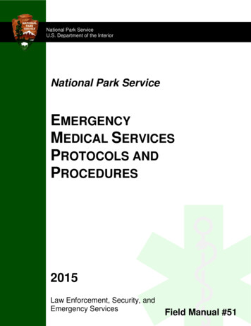
Reaction Module LEDReaction EAF2RF3BACKF42580SHIFT369.F5ENTERSTOPPower Up LEDFig. 1.1. iCycler.1.2 Features Graphical representation of protocols combined with standard language templates.User-friendly software, including menu driven software, ready-made protocol templatesand user-defined preference file.Direct modular upgrade to Real-Time PCR monitoring.Interchangeable reaction modules.Maximum sample flexibility; reaction modules accommodate 0.2-ml tubes, strips and96-well plates, 0.5-ml tubes, and 384-well plates.Temperature monitoring and control can be specified by instrument algorithm, in-sampleprobe, or reaction module block mode.Optional security feature for protocols and folders.Run results report and validation report.NIST-traceable temperature performance.1.3 System Set Up1.3.1 UnpackingThe iCycler is shipped in two boxes: Box with the chassis, power cord, instruction manual, and fuses.Box with the reaction module, regulatory documentation, the in-sample temperature probe(for the 96 x 0.2 ml block or the 60 x 0.5 ml block). This box may also include a firmwarupgrade disk and cable to ensure that the most current version of firmware is available forthe block system shipped.2
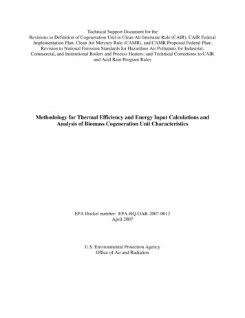
Carefully remove the contents of each shipping box. To remove the chassis, lift it out bygrasping the underside of the unit. Remove the plastic bag and inspect the instrument for anyexternal damage. Check off all parts against the supplied packing list.Your iCycler was carefully tested at the factory and was shipped in good working order. If anypart is missing or damaged, contact Bio-Rad Laboratories immediately.1.3.2 Voltage Conversion and Power Cable ConnectionThe iCycler is equipped to operate at 100–120 V or 220–240 V. Prior to connecting the powercord to the instrument's power entry module and the wall outlet, verify that the voltageindicated on the iCycler voltage selector switch matches your line voltage. If it does not, usethe following procedure to make the conversion. Refer to Figures 1.2 and 1.3.Warning: Failure to follow this procedure may result in damage to the unit andinvalidation of the warranty.VoltageSelectorSwitchFuseDrawerMade in the USAModel No.Serial No.InputMax. PoweriCyclerXXX BR 001BETA100-240 VAC 47-63 Hz950 VAParallelConnectorSerialConnectorFig. 1.2. iCycler rear view.1. Disconnect the power cord from the unit.2. Set the voltage select switch to 115 for 100–120 V operation or 230 for 220–240 Voperation using a flat-blade screwdriver3. Remove the fuse drawer with a small-blade screwdriver or similar tool.4. Pull the fuse holder out of the fuse drawer and, if necessary, replace the fuses with oneshaving the correct current rating.a.For 100–120 V operation: Use 8.0 A, 5 x 20 mm, Type T fuses.b.For 220–240 V operation: Use 4.0 A, 5 x 20 mm, Type T fuses.5. Reinsert the fuse drawer into the power entry module. Press gently until it snaps intoplace.6. Insert the power cord plug into the power entry module. Plug the power cord into aproperly grounded outlet.3
Note: The iCycler should be placed in a location that will allow free access to the main powerswitch.Power Entry ModuleFuse DrawerFig. 1.3. Changing fuses.1.3.3 Cable ConnectionsIn addition to the power cable connector, the rear panel of the iCycler contains connectorsfor the following devices: Serial port connector: Use this to connect a PC computer to the iCycler. This will allowyou to download reports to the computer. The serial cable must be shielded, with 9-pinmale/female D-connectors, and it must support transmit, receive, and ground. It should beconnected to PC COM 1 or COM 2. The cable should be wired for straight-throughconnection (pin 1 to pin 1, etc.) Parallel port connector: Use this to connect a PC-compatible printer to the iCycler. Thiswill allow you to print results and validation reports. The cable should be IEEE1284/Centronics-compatible and shielded, and it should have a male 25-pin D-connectorat the iCycler end. The connector at the other end should meet the requirements of yourprinter.Note: When using a printer, it is recommended that the printer be turned off before theiCycler.1.3.4 Removing and Attaching a Reaction ModuleThe iCycler must be powered down when removing or attaching reaction modules.Removing or attaching a reaction module while the iCycler is powered up may damagethe instrument.When removing or attaching a reaction module, allow approximately 16" clearance fromthe bench surface. The reaction modules are fastened by latches on each side.To remove a reaction module,1. Lift the reaction module lid handle.2. Slide the lid as far back as it will go.4
3. Lift the green latches on either side of the reaction module and rotate until they contactthe lid as shown in Figure 1.4.4. Lift out the reaction module using the handle.To attach a reaction module,1. Slide the lid of the reaction module as far back as possible.2. Rotate the green latches until they contact the lid as shown in Figure 1.4.3. Lift the reaction module by the handle.4. Insert reaction module. Note that the front portion will engage before the rear.5. Rotate the green latches down into their home position to clamp the reaction module inplace.6. Slide lid forward to close.Note: The rear sliding cover should move forward with the lid. If the rear sliding coverdoes not move forward, remove and reinsert the reaction module.Sliding Rear CoverReaction Module LED321456Fig. 1.4. Replacing a reaction module.1.3.5 Powering UpBefore powering up the iCycler, place it where there is sufficient ventilation and access tothe reaction module and the mains switch. We recommend at least 4" clearance to left and rightand 4" to rear. For convenience in handling the reaction module, 16" clearance from benchsurface is needed to remove the reaction module and about 12–13" to open the lid.Upon powering up, a Self Test screen is displayed, indicating that the machine is checkingthe status of its systems including the RAM and ROM, thermistors, lid heater power, lid heaterheating, control of peltier elements, the joule heaters, display, and keyboard. If any system fails,an appropriate message and instructions will be provided on the screen. If all systems pass, theLogon screen is displayed (see Figure 2.1.)There is one amber LED on the bottom right of the front panel of the iCycler that glows whenthe instrument is powered up (see Figure 1.1). If the LED does not glow, then the unit is notreceiving power. Refer to Section 6, Care and Maintenance.5
An amber LED that is off at block temperatures below 30 C; flashes at temperaturesbetween 30 C and 50 C, and glows steady when the temperature exceeds 50 C for allreaction modules except the 2x48 well module.When powering up an iCycler with a 2 x 48 x 0.2 ml reaction module, allow 10 minutesbefore initiating a protocol.1.4 Loading the Reaction ModuleFor optimal performance of the iCycler, we recommend Bio-Rad tubes, plates, andaccessories as follows:CatalogNumberProduct DescriptionReaction ModuleTWI-02010.2 ml Tubes With Domes Caps, natural,1,000 (2 bags of 500)96 x 0.2 ml2 x 48 x 0.2 mlTFI-02010.2 ml Tubes With Flat Caps, natural,1,00096 x 0.2 ml2 x 48 x 0.2 mlTBS-02010.2 ml 8-Tube Strips Without Caps, natural,12596 x 0.2 ml2 x 48 x 0.2 mlTCS-0801Domed 8-Cap Strips, for 0.2 ml tubes andplates, natural, 12096 x 0.2 ml2 x 48 x 0.2 mlTCS-0803Optical Flat 8-Cap Strips, for 0.2 ml tubesand plates, ultraclear, 12096 x 0.2 ml2 x 48 x 0.2 mlTBS-12010.2 ml 12-Tube Strips Without Caps, natural,10096 x 0.2 ml2 x 48 x 0.2 mlTCS-1201Domed 12-Cap Strips, for 0.2 ml tubes andplates, natural, 20096 x 0.2 ml2 x 48 x 0.2 mlTBI-05020.5 ml Tubes With Flat Caps, natural, 800(8 bags of 100)96 x 0.2 mlMLP-9601Multiplate 96-Well 0.2 ml Unskirted PCRPlates, natural, 296 x 0.2 mlMSP-3842Microseal 384-Well PCR Plates, version 2.0,natural, 50384 wellMSB-1001Microseal ‘B’ Adhesive Seals, 10096 x 0.2 ml223-944296-Well PCR Plate Sealing Mats, 596 x 0.2 mlThe recommended sample volume for 0.2 ml tubes or 96 well plates is 15–100 µl; forthe 0.5 ml tubes is 50–200 µl; and for the 384 well plates is 5–20 µl.Use of Thermal Isolation RingsThe iCycler Sealing Ring optimizes temperature isolation of the sample reaction blockarea. These sealing rings are intended for use with the iCycler 96 x 0.2 ml reactionmodule, and the 60 x 0.5 ml reaction module (Figure 1.5). The sealing ring for the 96-wellsystem is green, and the one for the 60 well system is blue.These Thermal Sealing Rings offer structural support, minimizing the number of tubesrequired in any experiment. Note that the thermal isolation ring has a slot for use with thesample probe. When using the sample probe for temperature control, position the sampleprobe to feed through this slot.6
The sealing ring should be positioned directly over the ridge surrounding the sampleblock area with the Bio-Rad logo towards the back of the instrument.The sealing ring is required for optimal performance in the 60-well block. Although notrequired for the 96-well system, it is highly recommended to prevent tube deformation andminimize ambient condensation that can build up in humid environments after long holdtimes (24 hours) at 4 C.Fig. 1.5. Use of Thermal Sealing Ring.When using the 96-well system without the sealing ring, please observe the followingloading pattern (Figure 1.6) to insure that tubes are not deformed when the lid is closed.One of Six Tubes1 x 96 Reaction ModuleFig. 1.6. To prevent tube deformation.1. Lift the handle of the reaction module and slide the lid toward the rear of the instrument.2. Load your plate or tubes into the reaction block.3. Slide the lid forward over the reaction block and lower the handle. Make sure that thehandle closes securely over the lip of the baffle on the front of the reaction module(Figure 1.7).7
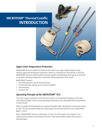
Handle must close over lipon Baffle of Reaction Module321456Fig. 1.7. Closing the iCycler Lid.1.5 iCycler KeypadThe iCycler keypad has 25 keys on the front panel (Figure 1.8). These keys are describedin the following table.Fig. 1.8. iCycler keypad.8
Table 1. Front Panel ControlsKey(s)DescriptionSoftkeys F1-F5The five function keys (referred to as "softkeys") are labeled F1through F5. These keys are used to navigate through thesoftware screens and make selections in the screen displays.The operations associated with these keys are displayed ininverse video immediately above the softkey. These operationschange as the display changes. For example, in the Homescreen, the F1 softkey will take you to the Protocol Library, andthe F2 softkey will enable you to Create a protocol.BACKThe Back key will return you to the immediately previous screenor, depending on the context, to some other, more appropriateprevious screen. From most places in the firmware you canrepeatedly press Back until, eventually, you return to the Homescreen. When the Home screen is displayed, the Back key hasno further function.When menus or option boxes are presented, Back acts as aCancel key.AlphanumericTo the right of the display are ten alphanumeric keys (keys0–9), which are arranged like the keys on a telephone. Eachnumeric key (except 1 and 0) is used to represent three ormore letters.The alphanumeric keys are usually used as number keys forthe entry of time, temperature, and cycle repeats.When entering a user, folder, or protocol name into a screendisplay, the keys automatically shift to alpha mode for the entryof letters. The word ALPHA is displayed in the top right cornerof the screen. You can toggle between alpha and numeric bypressing the SHIFT key. To enter uppercase letters, pressF2-Caps Lock before pressing the alphanumeric key.To specify an alphabetic character, press the key until thedesired character is displayed. For example, the 2 key is usedfor a, b or c entries. To input the letter a, press the 2 key once.To input b, press the 2 key twice and to input c, press the 2 keythree times. If the 2 key is pressed a fourth time, it will displaythe letter a.DECIMAL POINT (.)When entering numeric decimal values, press this key to entervalues after the decimal.INFINITYThe 0 key is labeled with an infinity symbol above the 0 to indicatethat it has a secondary function of Infinite Dwell Time. Like thealphabetic characters, this secondary function is accessed byfirst pressing the SHIFT key. The Infinity key is used to indicatedwell times that are to be terminated by user intervention.Typically this feature is used at the end of a protocol, but it can beused at other points as well. When an infinite dwell time isspecified, the iCycler will pause the protocol at the selectedtemperature until you terminate or resume execution. This isdiscussed further in Section 4, Running Protocols.9
Key(s)DescriptionCLEA
Thermal Cycler Instruction Manual Catalog Numbers 170-8720 170-8722 170-8724 170-8726 For Technical Service Call Your Local Bio-Rad Office or in the U.S. Call 1-800-4BIORAD (1-800-424-6723) NOTICE TO PURCHASER This base unit, Serial No. _, in combination with its immediately attached