Transcription
Lab 0ASA Firewall1
Lab Access SSID: ASAFirewall Password: Firewall George, Adam http://192.168.1.101 Matej, Bogdan http://192.168.1.1022
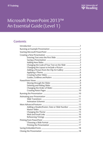
Topology3
0/1E0/1E0/0NICNICIP 3.110.2.2.1192.168.1.3192.168.3.3Subnet 5.0255.255.255.0Default tch PortS1 E0/0N/AN/AN/AS2 E0/0N/AS1 E0/1S2 E0/14
Configure basic settings for each router Configure host names as shown in the topology. Configure the interface IP addresses as shown in the IP addressing table.R1(config)# interface E0/0R1(config-if)# ip address X.X.X.X M.M.M.M To prevent the router from attempting to translate incorrectly entered commandsas though they were host names, disable DNS lookup.R1(config)# no ip domain-lookup5
Configure OSPF routing on the routers. Use the router ospf command in global configuration mode to enable OSPF on R1.R1(config)# router ospf 1 Configure the network statements for the networks on R1. Use an area ID of 0.R1(config-router)# network 192.168.1.0 0.0.0.255 area 0R1(config-router)# network 10.1.1.0 0.0.0.3 area 0 Configure OSPF on R2 and R3. Issue the passive-interface command to change the G0/1 interface on R1 and R3to passive.R1(config)# router ospf 1R1(config-router)# passive-interface g0/1R3(config)# router ospf 1R3(config-router)# passive-interface g0/16
Verify OSPF neighbors and routing information. Issue the show ip ospf neighbor command to verify that each router liststhe other routers in the network as neighbors. R1# show ip ospf neighborNeighbor ID10.2.2.2PriState0FULL/-Dead TimeAddressInterface00:00:3110.1.1.2Serial0/0/07
Configure PC host IP settings. Configure a static IP address, subnet mask, and default gateway for PC-A PC-C, as shown in the IP addressing table.8
Verify connectivity between PC-A and R3. Ping from R1 to R3. If the pings are not successful, troubleshoot the basic device configurationsbefore continuing. Ping from PC-A on the R1 LAN to PC-C on the R3 LAN.9
Configure and encrypt passwords on R1 and R3. Configure a minimum password length. Use the security passwords command to set a minimum password lengthof 10 characters.R1(config)# security passwords min-length 10 Configure the enable secret password on both routers. Use the type 9(SCRYPT) hashing algorithm.R1(config)# enable algorithm-type scrypt secret cisco1234510
Configure the basic console, auxiliary port, and vty lines. Configure a console password and enable login for router R1. For additionalsecurity, the exec-timeout command causes the line to log out after 5minutes of inactivity. The logging synchronous command prevents consolemessages from interrupting command entry. Note: To avoid repetitive logins during this lab, the exec timeout can be set to 00, which prevents it from expiring. However, this is not considered a goodsecurity practice.R1(config)# line console 0R1(config-line)# password ciscoconpassR1(config-line)# exec-timeout 5 0R1(config-line)# loginR1(config-line)# logging synchronous11
Configure the basic console, auxiliary port, and vty lines. Configure a password for the aux port for router R1.R1(config)# line aux 0R1(config-line)# password ciscoauxpassR1(config-line)# exec-timeout 5 0R1(config-line)# login Configure the password on the vty lines for router R1.R1(config)# line vty 0 4R1(config-line)# password ciscovtypassR1(config-line)# exec-timeout 5 0R1(config-line)# login Encrypt the console, aux, and vty passwords.R1(config)# service password-encryption Issue the show run command. Can you read the console, aux, and vty passwords12
Configure a login warning banner on routers R1 and R3. Configure a warning to unauthorized users using a message-of-the-day (MOTD)banner with the banner motd command. When a user connects to the router,the MOTD banner appears before the login prompt. In this example, the dollarsign ( ) is used to start and end the message.R1(config)# banner motd Unauthorized access strictlyprohibited! R1(config)# exit Exit privileged EXEC mode by using the disable or exit command andpress Enter to get started. If the banner does not appear correctly, re-create it using the banner motdcommand.13
Configure the local user database. Create a local user account with the type 9 (SCRYPT) hashing algorithm.R1(config)# username user01 algorithm-type scrypt secretuser01pass14
Configure local authentication for the console line and login Set the console line to use the locally defined login usernames and passwords.R1(config)# line console 0R1(config-line)# login local Exit to the initial router screen that displays:R1 con0 is now available. Press RETURN to get started. Log in using the user01 account and password previously defined.15
Test the new account by logging in from a Telnet session. From PC-A, establish a Telnet session with R1.PC-A telnet 192.168.1.1 Were you prompted for a user account? Explain. Set the vty lines to use the locally defined login accounts and configure thetransport input command to allow Telnet.R1(config)# line vty 0 4R1(config-line)# login localR1(config-line)# transport input telnetR1(config-line)# exit From PC-A, telnet R1 to R1 again.16
Configure a domain name. Enter global configuration mode and set the domain name.R1# conf tR1(config)# ip domain-name local.lab17
Configure a privileged user for login from the SSH client. Use the username command to create the user ID with the highest possibleprivilege level and a secret password.R1(config)# username Admin01 privilege 15 algorithm-typescrypt secret Admin01pass18
Configure the incoming vty lines. Specify a privilege level of 15 so that a user with the highest privilege level (15)will default to privileged EXEC mode when accessing the vty lines. Other userswill default to user EXEC mode. Use the local user accounts for mandatory loginand validation and accept only SSH connections.R1(config)# line vty 0 4R1(config-line)# privilege level 15R1(config-line)# login localR1(config-line)# transport input sshR1(config-line)# exit19
Erase existing key pairs on the router.R1(config)# crypto key zeroize rsa Note: If no keys exist, you might receive this message:% No Signature RSA Keys found in configuration.20
Generate the RSA encryption key pair for the router. The router uses the RSA key pair for authentication and encryption of transmitted SSHdata. Configure the RSA keys with 1024 for the number of modulus bits. The default is 512,and the range is from 360 to 2048.R1(config)# crypto key generate rsa general-keys modulus 1024 The name for the keys will be: R1.local.lab% The key modulus size is 1024 bits% Generating 1024 bit RSA keys, keys will be non-exportable.[OK]R1(config)#*Dec 16 21:24:16.175: %SSH-5-ENABLED: SSH 1.99 has been enabled Issue the ip ssh version 2 command to force the use of SSH version 2.R1(config)# ip ssh version 2R1(config)# exit21
Verify the SSH configuration. Use the show ip ssh command to see the current settings.R1# show ip ssh Fill in the following information based on the output of the show ip sshcommand.22
Configure SSH timeouts and authentication parameters. The default SSH timeouts and authentication parameters can be altered to bemore restrictive using the following commands.R1(config)# ip ssh time-out 90R1(config)# ip ssh authentication-retries 223
Set Up the NTP Master using Cisco IOS commands. Use the show clock command to display the current time set on the router.R2# show clock*19:48:38.858 UTC Wed Feb 18 2015 To set the time on the router, use the clock set time command.R2# clock set 20:12:00 Dec 17 2014R2#*Dec 17 20:12:18.000: %SYS-6-CLOCKUPDATE: System clock hasbeen updated from 01:20:26 UTC Mon Dec 15 2014 to 20:12:00UTC Wed Dec 17 2014, configured from console by admin onconsole.24
Set Up the NTP Master using Cisco IOS commands. Configure NTP authentication by defining the authentication key number, hashing type,and password that will be used for authentication. The password is case sensitive.R2# config tR2(config)# ntp authentication-key 1 md5 NTPpassword Configure the trusted key that will be used for authentication on R2.R2(config)# ntp trusted-key 1 Enable the NTP authentication feature on R2.R2(config)# ntp authenticate Configure R2 as the NTP master using the ntp master stratum-number command inglobal configuration mode. The stratum number indicates the distance from the originalsource. For this lab, use a stratum number of 3 on R2. When a device learns the timefrom an NTP source, its stratum number becomes one greater than the stratum numberof its source.R2(config)# ntp master 325
Configure R1 and R3 as NTP clients using the CLI. Configure NTP authentication by defining the authentication key number, hashing type,and password that will be used for authentication.R1# config tR1(config)# ntp authentication-key 1 md5 NTPpassword Configure the trusted key that will be used for authentication. This command providesprotection against accidentally synchronizing the device to a time source that is nottrusted.R1(config)# ntp trusted-key 1 Enable the NTP authentication feature.R1(config)# ntp authenticate R1 and R3 will become NTP clients of R2. Use the command ntp server hostname.The host name can also be an IP address. The command ntp update-calendarperiodically updates the calendar with the NTP time.R1(config)# ntp server 10.1.1.226
Configure R1 and R3 as NTP clients using the CLI. Verify that R1 has made an association with R2 with the show ntpassociations command. You can also use the more verbose version of thecommand by adding the detail argument. It might take some time for the NTPassociation to form.R1# show ntp associationsaddressref clock 10.1.1.2127.127.1.1stwhen314poll , # selected, candidate, -outlyer, x falseticker, configured Issue the debug ntp all command to see NTP activity on R1 as itsynchronizes with R2.R1# debug ntp all27
Install the syslog server. Tftpd32 includes a TFTP server, TFTP client, and a syslog server and viewer.The Kiwi Syslog Daemon is only a dedicated syslog server. You can use eitherwith this lab. Both are available as free versions and run on Microsoft Windows. If a syslog server is not currently installed on the host, download the latestversion of Tftpd32 from http://tftpd32.jounin.net or Kiwi fromhttp://www.kiwisyslog.com and install it on your desktop. If it is already installed,go to Step 2. Note: This lab uses the Ttftpd32 application for the syslog server functionality.28
Configure R1 to log messages to the syslog server Verify that you have connectivity between R1 and PC-A by pinging the R1 G0/1interface IP address 192.168.1.1. If it is not successful, troubleshoot as necessarybefore continuing. NTP was configured in Task 2 to synchronize the time on the network. Displaying thecorrect time and date in syslog messages is vital when using syslog to monitor anetwork. If the correct time and date of a message is not known, it can be difficult todetermine what network event caused the message. Verify that the timestamp service for logging is enabled on the router using the showrun command. Use the following command if the timestamp service is not enabled.R1(config)# service timestamps log datetime msec Configure the syslog service on the router to send syslog messages to the syslogserver.R1(config)# logging host 192.168.1.329
Configure the logging severity level on R1. Use the logging trap command to determine the options for the commandand the various trap levels available. Use the logging trap command to set the severity level for R1.R1(config)# logging trap warnings30
Display the current status of logging for R1. Use the show logging command to see the type and level of loggingenabled.R1# show logging31
Enable AAA On R3, enable services with the global configuration aaa new-model command.Because you are implementing local authentication, use local authentication asthe first method, and no authentication as the secondary method. If you were using an authentication method with a remote server, such asTACACS or RADIUS, you would configure a secondary authentication methodfor fallback if the server is unreachable. Normally, the secondary method is thelocal database. In this case, if no usernames are configured in the localdatabase, the router allows all users login access to the device.R3(config)# aaa new-model32
Implement AAA services for console access using the localdatabase. Create the default login authentication list by issuing the aaa authenticationlogin default method1[method2][method3] command with a method listusing the local and none keywords.R3(config)# aaa authentication login default local-case noneR3(config)# aaa authentication enable default enable Note: If you do not set up a default login authentication list, you could get locked out ofthe router and be forced to use the password recovery procedure for your specificrouter. Note: The local-case parameter is used to make usernames case-sensitive. Exit to the initial router screen that displays: R3 con0 is now available Press RETURN to get started.33
Create an AAA authentication profile for Telnet using the localdatabase. Create a unique authentication list for Telnet access to the router. This does nothave the fallback of no authentication, so if there are no usernames in the localdatabase, Telnet access is disabled. To create an authentication profile that isnot the default, specify a list name of TELNET LINES and apply it to the vtylines.R3(config)# aaa authentication login TELNET LINES localR3(config)# line vty 0 4R3(config-line)# login authentication TELNET LINES34
Use debug to verify user access. Activate debugging for AAA authentication.R3# debug aaa authentication AAA Authentication debugging is on Start a Telnet session from R2 to R3. Log in with username Admin01 and password Admin01pass. Observe the AAAauthentication events in the console session window. Debug messages similarto the following should be displayed.R3#Feb 20 08:45:49.383: AAA/BIND(0000000F): Bind i/fFeb 20 08:45:49.383: AAA/AUTHEN/LOGIN (0000000F): Pickmethod list 'TELNET LINES'35
ReConfigure the default login authentication list. Configure the list to first use RADIUS for the authentication service, and thennone. If no RADIUS server can be reached and authentication cannot beperformed, the router globally allows access without authentication. This is asafeguard measure in case the router starts up without connectivity to an activeRADIUS server.R1(config)# aaa authentication login default group radiusR1(config)# aaa authorization exec default group radius if-authenticated You could alternatively configure local authentication as the backupauthentication method instead. Note: If you do not set up a default login authentication list, you could get lockedout of the router and need to use the password recovery procedure for yourspecific router.36
Specify a RADIUS server. Use the radius server command to enter RADIUS server configuration mode.R1(config)# radius server RADSERVERGROUP Use the ? to view the sub-mode commands available for configuring a Radius server.R1(config-radius-server)# ?RADIUS server sub-mode commands:addressautomate-testerSpecify the radius server addressConfigure server automated testing.backoffRetry backoff pattern(Default is retransmits with constantdelay)exitkeyExit from RADIUS server configuration modePer-server encryption keynonon-standardNegate a command or set its defaultsAttributes to be parsed that violate RADIUS standardpacretransmitProtected Access Credential keyNumber of retries to active server (overrides default)timeoutTime to wait (in seconds) for this radius server to reply(overrides default)37
Specify address and key Use the address command to configure this IP address for PC-AR1(config-radius-server)#address ipv4 192.168.1.3 auth-port 1812 acct-port 1813 The key command is used for the secret password that is shared between theRADIUS server and the router (R1 in this case) and is used to authenticate theconnection between the router and the server before the user authenticationprocess takes place. Use the default NAS secret password of WinRadiusspecified on the Radius server (see Task 2, Step 5). Remember that passwordsare case-sensitive.R1(config-radius-server)# key WinRadiusR1(config-redius-server)# end38
FreeRadius Server 139
FreeRadius Server 240
6 Configure OSPF routing on the routers. Use the router ospf command in global configuration mode to enable OSPF on R1. R1(config)# router ospf 1 Configure the network statements for the networks on R1. Use an area ID of 0. R1(config-router)# network 192.168.1. 0.0.0.255 area 0 R1(config-router)# network 10.1.1.0 0.0.0.3 area 0 Configure OSPF on R2 and R3.