Transcription
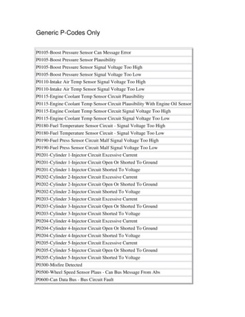
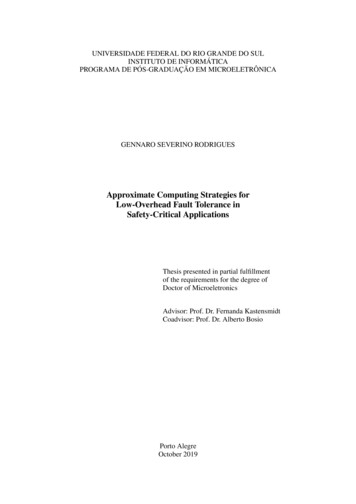
International Journal of Engineering Research & Technology (IJERT)ISSN: 2278-0181Vol. 4 Issue 03, March-2015Transmission Line Fault Analysis using BusImpedance Matrix MethodPrajakta V. Dhole1Farina S. Khan1First Year Engineering Department, JSPM's ImperialCollege of Engg. & Research, Wagholi, PuneSavitribai Phule Pune University,Pune, IndiaFirst Year Engineering Department, JSPM's ImperialCollege of Engg. & Research, Wagholi, PuneSavitribai Phule Pune University,Pune, IndiaAbstract -- The fault analysis is done for the three phasesymmetrical fault and the unsymmetrical faults. Theunsymmetrical faults include single line to ground, line to lineand double line to ground fault. The method employed is busimpedance matrix which has certain advantages overthevenin’s equivalent method. The advantage of this approachover conventional method is to make the analysis of threetypical un-symmetrical faults, namely single-line-to-groundfault, line-to-line fault and double-line-to-ground fault moreunified. So it is unnecessary to cumbersomely connect threesequence networks when calculating the fault voltages at eachbus and fault currents flowing from one bus to its neighboringbus.Keywords- Bus impedance matrix; fault analysis; faultimpedance; thevenin’s equivalent.3.Line-to-line fault (LL)4.Double line-to-ground fault (DLG)The most common type of faults by far is the SLG fault,followed in frequency of occurrence by the LL fault, DLGfault, and three-phase fault.Out of the above four faults, two are of the line-toground faults. Most of these occur as a result of insulatorflashover during electrical storms. The balanced threephase fault is the rarest in occurrence and the least complexin so far as the fault current calculations are concerned. Theother three unsymmetrical faults will require theknowledge and use of symmetrical components.Unsymmetrical faults cause unbalanced currents to flow inthe system. The method of symmetrical components is avery powerful tool which makes the calculations ofunsymmetrical faults almost as easy as the calculations of athree-phase fault.To analyze un-symmetrical faults, one needs to developpositive-, negative-, and zero-sequence networks of thepower system under study, based on which one furtherneed to work out the impedance of three theveninequivalent circuits as viewed from faulty point. Then thepositive-, negative- and zero-sequence components ofphase-a faulty-point-to-ground current can be calculated.To calculate three-phase currents flowing from one bus toits neighboring bus and three-phase voltages at each bus,one needs to connect three sequence networks uniquely foreach type of fault. This may make circuit drawing verycumbersome. Furthermore by using the network with threesequence networks connected, it is impossible to appreciatethe impedance matrix approach to calculate the sequencevoltage at each bus when fault occurs.To overcome these two drawbacks, paper [1] introducesa new approach to unify the analysis of three typicalunsymmetrical faults, namely single-line-to-ground fault,line-to-line fault and double-line-to-ground fault. This newmethod allows the analysis of three typical un-symmetricalfaults to share all steps except one. The only different stepis how to calculate the positive-, negative-, and zerosequence components of phase-a-to-ground fault current atfaulty point. It also makes impedance matrix approachmore understandable when used to calculate the sequencevoltages at each bus.I.INTRODUCTIONThe steady state operating mode of a power system isbalanced 3-phase ac. However due to sudden external orinternal changes in the system, this condition is disrupted.When the insulation of the system fails at one or morepoints or a conducting object comes in contact with a livepoint, a short circuit or fault occurs. A fault involving allthe three phases is known as symmetrical (balanced) faultwhile one involving only one or two phases is known asunsymmetrical fault. Majority of the faults areunsymmetrical. Fault calculations involve finding thevoltage and current distribution throughout the systemduring the fault. It is important to determine the values ofsystem voltages and currents during fault conditions so thatthe protective devices may beset to detect the fault and isolate the faulty portion of thesystem.II. FAULTS IN A THREE PHASE SYSTEM1.2.Symmetrical three-phase faultSingle line-to-ground fault (SLG)IJERTV4IS030919www.ijert.org(This work is licensed under a Creative Commons Attribution 4.0 International License.)948
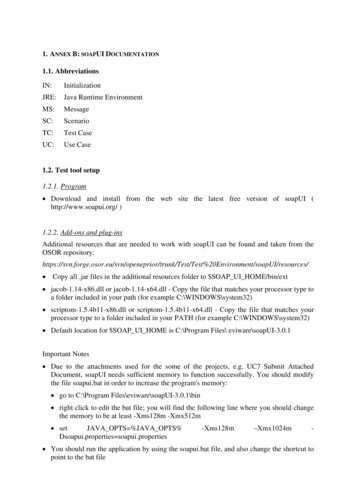
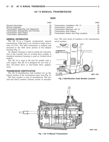
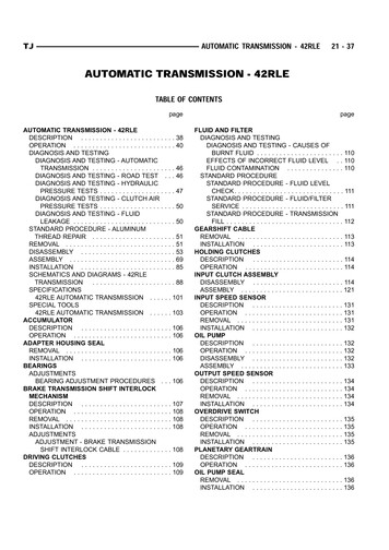
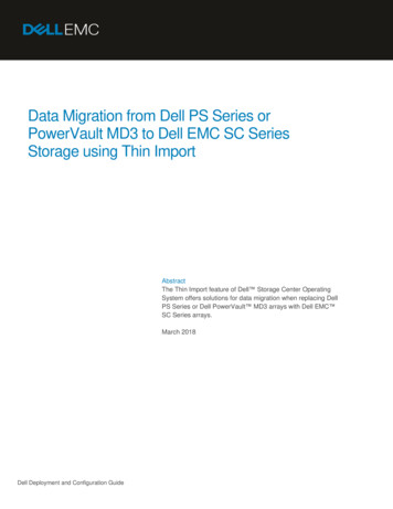
International Journal of Engineering Research & Technology (IJERT)ISSN: 2278-0181Vol. 4 Issue 03, March-2015All the above four faults (1, 2, 3, 4) are being solvedusing the bus impedance matrix.Fig. 3.Fig. 1.Double line to ground faultSingle line to ground faultIII. BUS IMPEDANCE MATRIX METHODWe can work out a universal representation of all threetypical un-symmetrical faults. This representation is validwith the imposition of different fault conditions for eachtypical un-symmetrical fault, such as for the single-line-toground fault, such as for the single-line-to-groundfault, the fault conditions being Vka ZfIfa, Ifb Ifc 0.Fig. 2.Line to line faultIn the following formulation, per-unit system isadopted. Zero-sequence voltage at each buscontributed by equivalent current source isdetermined by Y11 0 Y12 0 . Y1k 0 . Y1n 0 V1f 0 0 0 0 0 0 0 Y21 Y22 . Y2k . Y2n V2f 0 ::.:.: : : Y 0 Y 0 . Y 0 . Y 0 V 0 -I fa0 k1k2kkknkf ::::: : : : 0 0 0 0 0 0 Yn1 Yn2 . Ynk . Ynn Vnf where Y11 0 0 Y21 0 Y : Y 0 k1 : 0 Yn1IJERTV4IS030919Y12 0 .Y1k 0 . 0 Y22:. 0 Y2k:. 0 Yk2:.:0 Y kk:.: 0 Yn2. 0 Ynk.www.ijert.org(This work is licensed under a Creative Commons Attribution 4.0 International License.)Y1n 0 0 Y2n : 0 Ykn : 0 Ynn 949
International Journal of Engineering Research & Technology (IJERT)ISSN: 2278-0181Vol. 4 Issue 03, March-2015Sois the admittance matrix for the sub-transient or transientzero-sequence network. 0 0 V1f 0 -Z1kI fa 0 0 0 V2f -Z 2k I fa : : V 0 -Z 0 I 0 kf kk fa : : 0 0 0 Vnf -Z nk I fa Then V1f 0 Y 0 0 11 V2f Y21 0 : : V 0 Y 0 kf k1 : : 0 0 Vnf Yn1Y12 0 . Y1k 0 0 0 Y22:. Y2k.:Yk2 0 :. Y kk0 ::Yn2 0 . Ynk 0 . Y1n 0 . Y2n 0 .: . Ykn 0 :: . Ynn 0 0 0 : 0 Z 0 -I fa : 0 0 Z11 0 Z21 : Z 0 k1 : 0 Zn1In a similar way, positive-sequence voltage at each buscontributed by equivalent current source as is determinedby Y11 1 1 Y21 : Y 1 k1 : 1 Yn1Where, 0 Z11 0 Z21 0 :Z 0 Z k1 : 0 Zn1 0 0 : 0 -Ifa : 0 0 0 Z12. Z1kZ 220 . Z 2k0 : . :Z k20 . Z kk0 :::Z n20 . Z nk0 0 . Z1n . Z 2n0 . : . Z kn0 :: . Z nn0 0 Z12. 0 Z1k.Z 220 :.Z 2k0 :.Z k20 :.:0 Z kk:.:Z n20 .Z nk0 . 0 Z1n Z 2n0 : Z kn0 : Z nn0 Y12 1 . Y1k 1 . Y1n 1 V1f 1 0 Y22 1 . Y2k 1 . Y2n 1 V2f 1 0 : . : . : : : 1 Yk2 1 . Y kk1 . Ykn 1 Vkf 1 -Ifa ::::: : : Yn2 1 . Ynk 1 . Ynn 1 Vnf 1 0 This gives 1 V1f 1 Z11 1 1 V2f Z21 : : V 1 Z 1 kf k1 : : 1 1 Vnf Zn1 1 Z12. 1 Z1kZ 221 :.Z 2k1 :Z k21 :. Z kk1 ::Z n21 .Z nk1 1 . Z1n . Z 2n1 .: . Z kn1 :: . Z nn1 1 1 0 -Z1k I fa 0 1 1 -Z 2k I fa : : 1 1 1 -I fa -Z kk I fa : : 11 0 -Z I nk fa If pre-fault current is ignored, then the pre-fault voltageat each bus is the same and equal to that at fault bus kbefore fault occurs, which is assumed to be Vf. So thepositive sequence voltage at each bus when fault occurscan be written as follows.IJERTV4IS030919www.ijert.org(This work is licensed under a Creative Commons Attribution 4.0 International License.)950
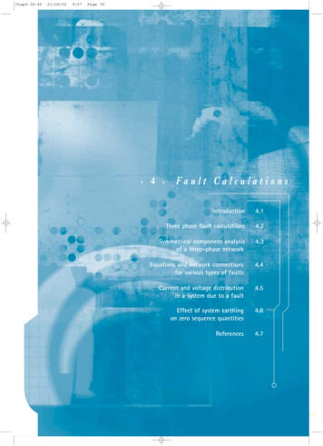
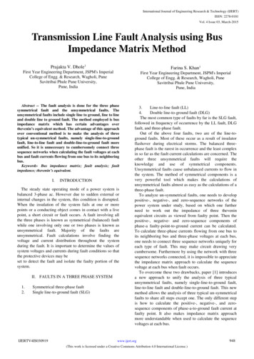
International Journal of Engineering Research & Technology (IJERT)ISSN: 2278-0181Vol. 4 Issue 03, March-2015 V1f 1 V1 1 V1f 1 V -Z1k 1 I fa1 1 1 1 f 1 1 V2f V2 V2f Vf -Z2k Ifa : : : : : V 1 V 1 V 1 Vf -Z 1 I 1 kf k kf kk fa : : : : : 1 1 1 Vf 1 1 Vnf Vn Vnf -Znk Ifa ItemBase MVAVoltage 20 kV20 kV20/220 kV20/220 kV220 kV220 kV220 250.150.250.050.050.100.100.300.350.7125 Vf -Z1k 1 I fa1 1 1 Vf -Z2k Ifa : V -Z 1 I 1 f kk fa : 1 1 Vf -Znk Ifa In a similar way, the negative-sequence voltage at eachbus can be computed by 2 2 V1f 2 -Z1kI fa 2 2 2 V2f -Z 2k I fa : : V 2 -Z 2 I 2 kk fa kf : : 2 2 2 Vnf -Z nk I fa 2 Z11 2 Z21 :Z 2 2 Z k1 : 2 Zn1TABLEI.Fig. 4.Single line diagram 1IV. MATHEMATICAL ANALYSISA. Sequence impedance networksFirstly let us obtain the sequence impedancenetworks. From the data given in table 4.1 thefollowing positive, negative and zero sequenceimpedance networks are obtained in fig.4.6, 4.7 and4.8 respectively. 2 2 2 Z12. Z1k. Z1n Z 222 . Z 2k2 . Z 2n2 : . : . : Z k22 . Z kk2 . Z kn2 ::::: Z n22 . Z nk2 . Z nn2 POWER SYSTEM NETWORK PARAMETERSFig. 5.IJERTV4IS030919Positive Sequence impedance networkwww.ijert.org(This work is licensed under a Creative Commons Attribution 4.0 International License.)951
International Journal of Engineering Research & Technology (IJERT)ISSN: 2278-0181Vol. 4 Issue 03, March-2015Fig. 9.Fig. 6.21Ybus YbusFig. 7.Positive Sequence admittance networkNegative Sequence impedance networkj6.667 -j18.667 j8 j8-j16j4 j6.667j4 -j10.667 Zero Sequence impedance networkFig. 10.Zero Sequence admittance networkj3.3333 j2.8571 -j8.690 Y j3.3333 -j14.7368 j1.4035 j2.8571 j1.4035 -j4.2606 0busB. IMPEDANCE MATRICESThe impedance matrices are obtained from the admittancematrices.Z1busFig. 8.IJERTV4IS030919Positive Sequence admittance network j0.1450 j0.1050 j0.1300j0.1050j0.1450j0.1200j0.1300 j0.1200 j0.2200 j0.1820Z0bus j0.0545 j0.1400j0.0545j0.0864j0.0650j0.1400 j0.0650 j0.3500 Z2buswww.ijert.org(This work is licensed under a Creative Commons Attribution 4.0 International License.)952
International Journal of Engineering Research & Technology (IJERT)ISSN: 2278-0181Vol. 4 Issue 03, March-2015C. Single Line To Ground Fault At Bus 3 Through AFault Impedance Of J0.1When single line to ground fault occurs, the sequencecomponents of fault current at bus three are given byI1f3 I2f3 I0f3 Vk (0)Z Z2kk Z0kk 3Zf1kkV3 (0) 120Z33 Z33 Z33 3Zf 1 00j0.22 j0.22 j0.35 3(j0.1)1 0 0j1.09At bus 10 0 Vf10 0-Z13I3 0-j0.14(-j0.9174) 0.1284 1 11 1 0.8807 V V(0)-Z13I 3 f1 1 1-j0.13(-j0.9174) 2 2 Vf12 0-Z13I3 0-j0.13(-j0.9174) 0.1193 At bus2 Vf20 0-Z023I30 1 11 1 Vf2 V2 (0)-Z23I3 Vf22 0-Z223I32 0-j0.065(-j0.9174) 1-j0.120(-j0.9174) 0-j0.120(-j0.9174) 0.0596 0.8899 0.1101 Vf30 0-Z023I30 0-j0.35(-j0.9174) 1 1 1 1 Vf3 V3 (0)-Z33I3 1-j0.22(-j0.9174) 2 2 Vf32 0-Z33I3 0-j0.22(-j0.9174) 0.3211 0.7982 0.2018 At bus3The voltages during fault are -j0.9174 p.u.At bus 1The fault current is Iaf3 1 1 b 2 If3 1 a Icf3 1 a 0 1 If3 a I 0f3 a 2 I0f3 Vf1a 1 1 b 2 Vf1 1 a Vf1c 1 a 1 Vf10 1 12 a Vf11 1 aa 2 Vf12 1 a1 a a 2 0.1284 0.8807 0.1193 1 a a 2 0.0596 0.8899 0.1101 1 a a 2 0.3211 0.7982 0.2018 0.633 000 1.0046 120.45 1.0046 120.450 3I0f3 0 0 At bus 2 Vf2a 1 1 b 2 Vf2 1 a Vf2c 1 a 3(-j0.9174) 0 01 Vf20 1 12 a Vf21 1 aa 2 Vf22 1 a 0.7207 00 0.9757 117.430 0.9757 117.430 -j2.7522 0 0 At bus 3 2.7523 900 0 0 Vf3a 1 1 b 2 Vf3 1 a Vf3c 1 a 1 Vf30 1 1 2a Vf31 1 aa 2 Vf32 1 aThe symmetrical components of voltages during fault atbuses 1, 2 and 3IJERTV4IS030919www.ijert.org(This work is licensed under a Creative Commons Attribution 4.0 International License.)953
International Journal of Engineering Research & Technology (IJERT)ISSN: 2278-0181Vol. 4 Issue 03, March-2015 0.2752 00 0 1.0647 125.56 1.0647 125.560 V.VI.[1]CONCLUSION[2]This paper presents a method to tackle typical unsymmetrical faults. It is found that the bus impedancematrix method involves comparatively less computationsthan the thevenin’s equivalent method. The proposedapproach has another advantage over traditional methodthat it is more intuitive when matrix approach is adopted totackle a fault problem.IJERTV4IS030919REFERENCESDaming Zhang,”An alternative approach to analyze unsymmetrical faults in power system”. TENCON 2009, fromieeexplore.B. R. Gupta, Power System Analysis and Design, publishedby S. Chand and Company Ltd., p.265.www.ijert.org(This work is licensed under a Creative Commons Attribution 4.0 International License.)954
bus and fault currents flowing from one bus to its neighboring bus. Keywords- Bus impedance matrix; fault analysis; fault impedance; thevenin's equivalent. I. INTRODUCTION The steady state operating mode of a power system is balanced 3-phase ac. However due to sudden external or internal changes in the system, this condition is disrupted.