Transcription
LTE/LTE-A Jamming, Spoofing, and Sniffing:Threat Assessment and MitigationMarc Lichtman1 , Roger Piqueras Jover2 , Mina Labib1 ,Raghunandan Rao1 , Vuk Marojevic1 , Jeffrey H. Reed11Virginia Tech, Blacksburg, VA, USA2Bloomberg LP, New York, NY, USAAbstractLTE is currently being proposed for use in a nationwide wireless broadband public safety network inthe US as well as for other critical applications, where reliable communication is essential for safety. Unfortunately, like any wireless technology, disruption of these networks is possible through radio jamming.This article investigates the extent to which LTE is vulnerable to RF jamming, spoofing, and sniffingand assesses different physical layer threats that could affect next-generation critical communicationnetworks. In addition, we examine how sniffing the LTE broadcast messages can aid an adversary in anattack. The weakest links of LTE are identified and used to establish an overall threat assessment. Lastly,we provide a survey of LTE jamming and spoofing mitigation techniques that have been proposed inopen literature.Index TermsLong-Term Evolution (LTE), LTE-Advanced, LTE security, jamming, spoofingI. I NTRODUCTIONThe Long Term Evolution (LTE) has been standardized by the 3rd Generation Partnership Project(3GPP) to meet the growing demand in cellular data traffic. LTE offers better coverage, enhanced systemcapacity, higher spectral efficiency, lower latency, and higher data rates than its predecessors in a costeffective manner. True to its namesake, LTE has been be able to keep pace with the rapid evolution oftechnology by introducing LTE-Advanced (LTE-A) for even higher data rates and capacity, more reliablecoverage, and higher spectral efficiency. At the time of writing, there are 422 commercially launchedLTE networks in 147 countries, out of which 95 operators have commercially launched LTE-A carrieraggregation systems. LTE/LTE-A is unarguably the primary standard for 4G cellular technology and is
1well on its way to becoming the primary global cellular standard. In addition to providing commercialcommunications services, cellular networks are used to broadcast emergency information, announcingnatural disasters and other crises. Over the next decade we will likely become further dependent oncommercial cellular networks based on LTE, which is why we must ensure it is secure and availablewhen and where it’s needed. Unfortunately, like any wireless technology, disruption through deliberateradio frequency (RF) interference, or jamming, is possible.In the U.S., LTE is being used as a framework for the nationwide public safety network known asFirstNet. The objective of FirstNet is to provide a nationwide wireless broadband interoperable publicsafety network that provides reliable communications among first responders. Of greatest concern areemergencies caused by an adversary, such as a terrorist organization, whose attack may involve radiojamming against cellular networks (including FirstNet) to ensure disarray and cause further panic. Assuch, anti-jamming countermeasures need to be considered.The U.S. military has considered using ad-hoc LTE-based networks to keep soldiers on the battlefieldconnected, as well as for shipborne communication with naval aircraft. Unlike military standards, cellularstandards are publicly available, meaning that adversaries may leverage this knowledge and target weakpoints in the protocol to enhance the efficacy of their attacks. Radio jamming attacks are a serious threatto any military or battlefield communications link and must be accounted for.Attacks on LTE can be grouped into two broad categories: Denial of Service (DoS) and informationextraction. Jamming attacks are typically used to cause service disruption or DoS; attacks that extractinformation or cause DoS by targeting the higher layers fall under the category of cyber-attacks. Radiojamming is broadly defined as an attack in which a jammer transmits energy to disrupt reliable datacommunication. Jamming is performed through a RF attack vector, while cyber-attacks use networkattack vectors. In this article we are only concerned with jamming. An important property of jammingis that it always targets the receiver (as opposed to the transmitter), regardless of how close the jammeris to the transmitting node. Thus, jamming the LTE downlink, the signal transmitted by a base stationand received by mobile devices, targets the mobile devices, whereas jamming the uplink targets the basestation. RF spoofing refers to transmitting a fake signal meant to masquerade as an actual signal [1].Protocol-aware jamming attacks against LTE networks are primarily enabled by the openness of theprotocol. Moreover, the broadcast messages transmitted by LTE base stations do not use any means ofencryption. As a result, all sorts of essential network configuration details can be easily eavesdroppedwith low-cost software radios, a process we refer to as sniffing. This information can aid attackers inoptimizing and crafting attacks against LTE-based networks.
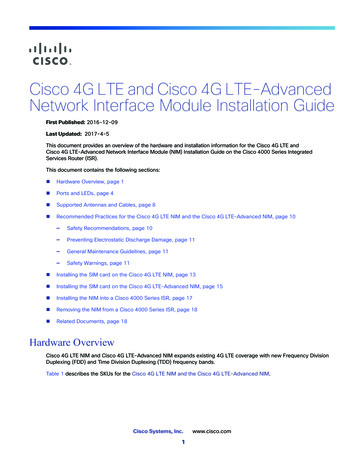
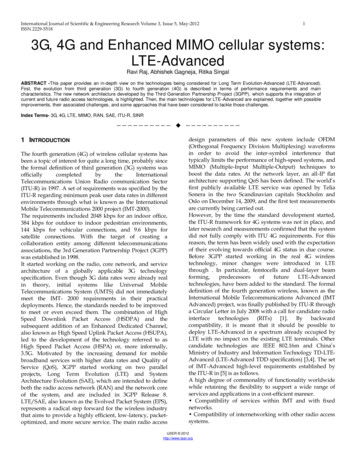
2The objectives of this article are to outline and motivate the need for high availability LTE networks,provide insight into physical layer vulnerabilities of LTE, and survey mitigation techniques that canharden the physical layer of next generation LTE and LTE-A deployments. The remainder of this articleis organized as follows. Section II provides a brief background on the physical layer of LTE. In SectionIII we investigate the individual channels and signals of LTE and analyze their vulnerabilities to jammingand spoofing. Section IV offers a comparison of attacks in terms of efficiency and complexity, SectionV surveys mitigation techniques found in literature, and Section VI concludes.II. BACKGROUND OF LTEOrthogonal frequency-division multiple access (OFDMA) is the channel access scheme used in theLTE downlink. OFDMA uses orthogonal frequency division multiplexing (OFDM) as the underlyingmodulation scheme and transmits a large number of parallel subcarriers with different blocks designatedto different users. For example, when LTE is configured for a 10 MHz bandwidth (the most commonconfiguration in the U.S.), there are 600 subcarriers in the downlink signal. Within one symbol, eachsubcarrier carries separate bits of information, resulting in information being mapped in both the time andfrequency domains. This leads to the OFDM time-frequency lattice, which is a two-dimensional grid usedto represent how information is mapped to physical resources. In LTE, one subcarrier over one OFDMsymbol interval is called a resource element, as shown in Figure 1. The entire frame is 10 millisecondslong, and frames repeat continuously.ResourceElementTimeFig. 1.Depiction of the OFDM time-frequency latticeSingle carrier-frequency division multiple access (SC-FDMA) is the multiple-access scheme used forthe LTE uplink. Uplink and downlink transmission happen either in different bands (frequency-division
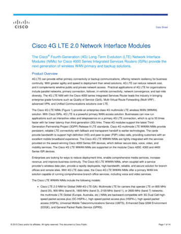
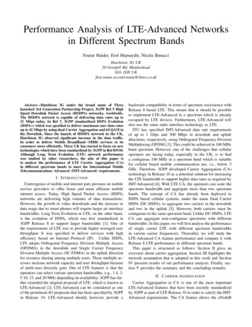
3duplex mode) or in the same band (time-division duplex mode). However, unlike in OFDMA, informationis spread across several subcarriers.LTE user devices–cellphones, tablets, and dongles, among others–are known as User Equipment (UE).The UE accesses the LTE network by connecting to an LTE base station, called an evolved NodeB oreNodeB. A UE typically attaches to only one eNodeB at a time, but constantly monitors the surroundingcells for the purpose of assisting the network in the handover process. In addition, UEs can sometimesroam (depending on the network’s policy) in other 4G, 3G, or 2G networks when their home LTE networkis unavailable.The LTE downlink and uplink signals are made up of “physical channels” and “physical signals”.These physical channels and signals are multiplexed together in time and frequency, and mapped ontothe time-frequency frame lattice. The mapping of physical channels within the LTE frame is definedin the broadcast messages sent by each base station. This method of information mapping allows ajammer to selectively jam information contained in specific Resource Elements (RE) or interfere withspecific physical downlink channels or signals. Figures 2 and 3 show the mapping of downlink and uplinkLTE frames respectively, when using frequency division duplex mode. Each color represents a differentphysical control channel or signal, whereas the white spaces represent data.LTE-A networks are an evolution of LTE. They use the same resource structure as LTE (shown inFigures 2 and 3) and add additional signalling and resources to support carrier aggregation, coordinatedmulti-point (CoMP) transmission and reception, and other LTE-Advanced features that are beyond thescope of this paper.III. V ULNERABILITY OF P HYSICAL C HANNELS AND S IGNALSThe following subsections investigate the various LTE physical channels and signals as well as discusspotential threats that could cause communications denial. All threats analyzed in this paper are fundamental to the protocol and thus apply to LTE and LTE-A networks. Table I highlights the parametersassociated with each physical channel and signal and will be referenced throughout the remainder of thisarticle.A. Synchronization SignalsThe Primary Synchronization Signal (PSS) is a downlink synchronization signal, received by the UEin order to find and synchronize to a cell (macro-cell base stations typically have three cells, also knownas sectors, each). By detecting the PSS, the UE determines the cell’s physical layer identity and acquires
Frequency4TimeControl Format Indicator Channel (PCFICH)Hybrid ARQ Indicator Channel (PHICH)Downlink Control Channel (PDCCH)Downlink Shared Channel (a.k.a. Data)Primary Synchronization Signal (PSS)Secondary Synchronization Signal (SSS)Broadcast Channel (PBCH)Cell-Specific Reference Signal (CRS a.k.a. Pilots)UnusedFig. 2.The LTE Downlink Signal, showing one full 10 millisecond frame (left), and the central 1.4 MHz of the same frame(right)PUCCHPRACHPRACHFrequencyPUSCH (Data)PUCCHTimeFig. 3.The LTE Uplink Signaltime and frequency synchronization. The Secondary Synchronization Signal (SSS) provides the UE withthe physical cell identity group. The physical cell identity group together with the physical layer identityprovides the full Physical Cell Identity (PCI). Through the SSS, the UE also learns about the CyclicPrefix (CP) type and the duplexing mode used by the cell.Jamming the PSS or SSS requires fairly high power, because they are designed to be detectable ata low signal-to-noise ratio (SNR). It has been shown that a more effective method for attacking thePSS is to use RF spoofing, to prevent the UE from detecting the real PSS of a given cell [2]. PSSspoofing essentially means that the attacker transmits a fake PSS, asynchronous to the LTE frame (i.e.,
5not overlapping in time with the real PSS) and at higher power.In order to understand the effect of PSS spoofing, we point out that the 3GPP LTE specificationstates that “the UE needs to search only for the strongest cell” at any given frequency [3]. The LTEspecifications do not specify the behavior of the UE when it detects a valid PSS with no associated SSS.Hence, this will be implementation-specific. However, if the PSS and SSS are both spoofed, the 3GPPspecification for the Radio Resource Control (RRC) layer [4] states that if the UE is in the idle modeand does not receive the Master Information Block (MIB) message after receiving the PSS and SSS, theUE shall treat this cell as “barred” and is allowed to select the second strongest cell within the samefrequency. Since the 3GPP specifications do not allow the UE to select the second strongest cell in mostcases, as mentioned before, UE baseband chips may overlook the importance of choosing the secondstrongest cell in this particular case for the sake of simplifying the interface between the physical layer(PHY) and the RRC layer.B. Downlink Reference SignalAn OFDM receiver needs to estimate the channel and perform equalization prior to decoding information. In OFDM systems, pilots or reference symbols are therefore transmitted on specific subcarriers inparallel with the data. These reference symbols are generated at the PHY layer and collectively called theCell-Specific Reference Signal (CRS) in the LTE downlink (see Figure 2). The CRS occupies roughly14% of the resource elements in a frame. The symbols are modulated with Quadrature Phase Shift Keying(QPSK) and are generated from a length-31 Gold sequence, which is initialized with a value based onthe cell ID. The cell ID also determines the location of the CRS in LTE resource lattice.It has been shown that jamming a subcarrier that carries pilots leads to a higher error rate than jammingone that contains only data [5], [6]. This is so because the adjacent subcarriers are also affected, due tothe nature of channel estimation. For a jammer to surgically transmit noise on top of the CRS, it mustdetect the target eNodeB’s PSS and SSS first to retrieve the cell ID. The jammer must also synchronizeits transmissions with the target cell, using the PSS and SSS. However, it does not need to be perfectlysynchronized, due to LTE’s long symbol duration of 66.7 microseconds. Even if the difference in the signalpath lengths to the UE were 5 miles, the propagation delay difference would only be 27 microseconds,which could easily be compensated for, if needed, by the jammer transmitting a fraction of a symbollonger each time. This applies to all synchronous jamming attacks discussed in this article.Asynchronous multi-tone jamming of CRS is also possible for a jammer with a low-complexitytransceiver, where there is no need for synchronization of the jammer with the eNodeB. This strategy
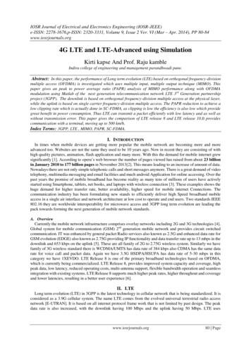
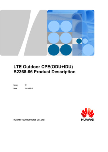
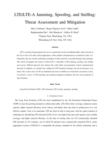
6involves transmitting noise on all CRS subcarriers (one third of all subcarriers) at a 100% duty-cycle.However, this would come at the cost of about seven times more power than the synchronous case andwould lead to a threat that is only slightly more effective than jamming the entire downlink frame.C. Downlink Broadcast ChannelAfter synchronizing with the cell and with the help of the CRS, the UE receives more informationabout the cell by decoding the Master Information Block (MIB), which is transmitted over the PhysicalBroadcast Channel (PBCH). The MIB contains information essential for initial access to a cell. It consistsof 14 bits that contain the downlink system bandwidth, information allowing frame synchronization, andother control information [7]. It is mapped to the center 72 subcarriers, on the first 1 millisecond subframe of every frame. The PBCH is transmitted using QPSK, and uses a 16-bit cyclic redundancy check(CRC) as a form of error detection. Against a 10 MHz signal, PBCH jamming only requires jammingabout 10% of the downlink subcarriers with a 3% duty-cycle, making it a very efficient synchronousjamming attack.While jamming the PBCH is of concern, simply sniffing it may give the adversary information useful tomore efficient attacks. Information carried over the PBCH allows the UE to determine the location of theSystem Information Block (SIB) messages, which are carried over the Physical Downlink Control Channel(PDCCH). These messages indicate the complete configuration of the cell and other critical informationof the mobile network, including the eNodeB’s idle timer [4], the configuration of the Physical RandomAccess Channel (PRACH), and the configuration of the Paging Channel (PCH).As illustrated in Figure 4, which was obtained with the Sanjole LTE sniffing tool, the entirety of theinformation broadcasted by all eNodeBs in the MIB and SIB messages is sent in the clear. This allows anadversary to sniff this traffic and extract all details about cell and network configurations. For example,sniffing the SIB1 message allows identifying the mobile operator running the eNodeB. In the case of apublic safety LTE deployment, a passive sniffer could identify the specific cells that are deployed forcritical communications and distinguish them from mobile operator eNodeBs.Having complete knowledge of the MIB and SIB messages could also be leveraged by an attacker todetermine the location of the PRACH in order to efficiently jam it, as discussed in Section III-H. Othertypes of higher-layer network attacks are enabled as well, such as the control plane “signaling overload”threat [8].
7Fig. 4.Real MIB and SIB1 Messages Captured from a Production NetworkD. Downlink Control ChannelsThe Physical Control Format Indicator Channel (PCFICH) is used to send the UE information regarding where the PDCCH is located in the time-frequency lattice. Without successful decoding of thisinformation, the UE will not be able to decode the PDCCH. The PDCCH contains information aboutthe UE uplink and downlink resource allocation, which is vital for receiving LTE service. Although it ispossible to jam the PDCCH directly, we will first discuss jamming the PCFICH.The PCFICH appears only in the first OFDM symbol in each subframe and occupies a total of 16 REs.In other words, it is an extremely sparse channel, making it vulnerable to efficient jamming. Jammingthe PCFICH consists of transmitting on top of the 16 REs that carry the PCFICH. The resource elementsused for the PCFICH are shown in blue in Figure 2. The resource mapping is not static, but, rather,determined by the eNodeB’s PCI [9], which the jammer can acquire through the PSS and SSS. This alsolimits a PCFICH jamming attack to a single cell, although multiple attacks could be launched by a singlejammer.Jamming the PDCCH also requires synchronization with the cell, but it is much less sparse than the
8PCFICH, making it a less effective jamming attack. In addition, since the PDCCH size varies betweenone and three OFDM symbols, the jammer needs to decode the PCFICH first in order to launch aneffective attack with the least amount of power.E. Hybrid-ARQ Indicator ChannelPositive and negative acknowledgments (ACKs/NACKs) for uplink packets are sent on the downlinkchannel called the Physical Hybrid-ARQ Indicator Channel (PHICH). The PHICH uses BPSK withrepetition-3 coding [9]. This physical channel is fairly sparse, and thus PHICH Jamming is a threatworth considering.F. Downlink and Uplink User DataThe Physical Downlink Shared Channel (PDSCH) and Physical Uplink Shared Channel (PUSCH) areused to transmit user data from the eNodeB to the UE and vice versa. While surgically jamming thesechannels is possible, the adversary might as well jam the entire LTE signal. Thus, PDSCH and PUSCHjamming are two of the least important threats to consider.However, it is possible to jam a specific user’s uplink transmissions. Doing so would require extensivedecoding of control information and knowledge of the user’s temporary mobile identity number. Thismakes it an extremely complex attack that might be considered a combination of jamming and cyberattack. We, therefore, do not include it in the vulnerability assessment.G. Uplink Control ChannelThe UE uses the Physical Uplink Control Channel (PUCCH) to send a variety of uplink controlinformation (UCI) to the eNodeB, including scheduling requests, Hybrid Automatic Repeat Request(HARQ) acknowledgments, and channel quality indicators. The UCI is mapped to the resource blocks onthe edges of the system bandwidth, as shown in Figure 3. This allows PUCCH jamming to be possiblewhen the jammer only knows the LTE system bandwidth and center frequency. For an uplink bandwidthof 10 MHz, roughly 16 resource blocks (or 192 subcarriers) are allocated to the PUCCH [9]. Therefore,PUCCH jamming requires jamming about 25% - 30% of the uplink system bandwidth. The PUCCH ismodulated with a combination of BPSK and QPSK, and uses 1/3 rate convolutional coding. Because ofits low complexity, PUCCH jamming is an important threat to consider. Also, note that uplink jamminghas an impact on the entire cell as opposed to locally around the jammer.
9TABLE IP HYSICAL C HANNEL AND S IGNAL M ODULATION S CHEME , C ODING T YPE AND R ATE , S PARSITY, S YNCHRONIZATIONR EQUIREMENT, AND MINIMUM J/S TO CAUSE D O SChannel/SignalModulationCodingCoding Rate% of REsSynch. RequiredJ/S CHJ/S FPDSCH{4,16,64}-QAMTurboAdaptive85%No0 dB-1 dBPBCHQPSKConvolutional1/480.3%Yes0 dB-25 dBPCFICHQPSKBlock1/160.2%Yes0 dB-27 dBPDCCHQPSKConvolutional1/37%Yes-5 dB-16.5 dBPHICHBPSKRepetition1/31.5%Yes3 dB-15 dBPUSCH{4,16,64}-QAMTurboAdaptive 75%No0 dB-1 dBPUCCHBPSK, QPSKConvolutional1/3 25%No-5 dB-11 dBPRACHZadoff-Chu SequenceN/AN/A 2%Yes10 dB-7 dBPSS (Spoofing)Zadoff-Chu SequenceN/AN/A0.45%No3 dB-20.5 dBSSSM-sequencesN/AN/A0.2%Yes15 dB-12 dBCRSQPSKN/AN/A5%Yes5 dB-8 dBH. Random Access ChannelAfter the initial cell search, the UE initiates the random access procedure with the objective to establisha RRC connection with the network. By transmitting the random access preamble on the PRACH, a UElets the eNodeB know of its presence and that it wants to connect to the cell. The specific location ofthe PRACH is conveyed to the UE in the SIB2 message, which is carried over the PDCCH. Therefore,to effectively jam the PRACH, the jammer must decode the SIB2 message fields. It is important to notethat a successful jamming attack against the PRACH will prevent new UEs from accessing a base station,but will not cause immediate DoS for active UEs. However, any active UE transitioning between idleand connected RRC states will be blocked, resulting in all devices within a cell being blocked within arather short period of time.IV. V ULNERABILITY A SSESSMENTWe have discussed several jamming and spoofing attacks against LTE. This section compares theseattacks in terms of efficiency and complexity to quantify the vulnerability of LTE and determine itsweakest links. First, we need to introduce two different ways of measuring the received jammer-to-signalratio (J/S), that is, the ratio of the received jamming signal power to the received LTE signal power. Twodifferent J/S metrics are required because there are two different ways to observe J/S.
10We will define J/S CH as the J/S that only takes into account the specific subcarriers and OFDMsymbols (a.k.a. REs) of the channel or signal being jammed. For example, when jamming the broadcastchannel (the light blue region in Figure 2), it is assumed the jammer will place its energy on top of thebroadcast channel in time and frequency, and not transmit on any other REs. Thus, J/S CH correspondsto the received power from the jammer divided by the received power of only the broadcast channel, notthe entire downlink signal.J/S averaged over an entire frame will be referred to as J/S F . Using the previous example of jammingthe broadcast channel, J/S F corresponds to the received power from the jammer divided by the receivedpower of the accumulated signal power over the entire 10 ms LTE uplink or downlink frame. The J/S Fmetric provides a convenient way to compare each jamming attack against the baseline attack, which isjamming the entire downlink or uplink signal.Note that J/S alone does not given enough information to determine how large an area around thejammer is jammed (i.e., the radius of effect). Link budgets, which take into account factors like thejammer’s transmit power and channel attenuation, are needed to determine such information.The vulnerability of each channel or signal is based primarily on three factors:1) The sparsity of the channel with respect to the entire downlink or uplink frame, i.e. the percent ofREs used for the channel.2) The jamming power needed to significantly corrupt the channel or signal, which we measure usingthe metric J/S CH .3) The complexity of the jammer required to perform such an attack, mostly based on whethersynchronization to the cell is needed or not.This information for each channel and signal is summarized in Table I. The sparsity can be combinedwith the minimum J/S CH needed to cause immediate denial of the channel or signal to find anapproximation for the corresponding J/S F . This is an approximation because it assumes a uniformpower spectral density across the LTE downlink or uplink signal, which is not the case in real worlddeployments. From the perspective of a jammer trying to minimize its power consumption and be moredifficult to detect, a lower J/S F is better.The jamming portion of the vulnerability assessment involved a series of experiments using bothsimulation and tests with commercial LTE equipment [10]. These experiments were meant to determinethe approximate J/S CH needed for each attack to cause DoS. First, we developed each of the downlinkjamming attacks using a system bandwidth of 10 MHz and one UE. We used the open-source, 3GPPcompliant LTE emulation library known as srsLTE, a library that provides a full physical layer software
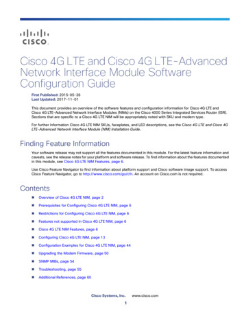
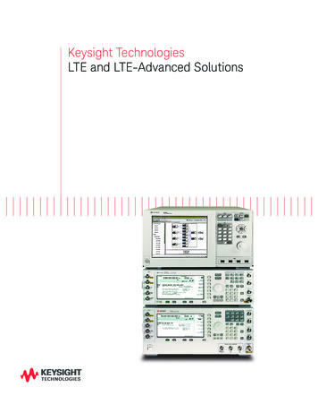
11radio implementation for both the LTE downlink and uplink. It allows full operation of a software-radiobased eNodeB, with ability to transmit and receive on all physical channels. We define the minimumJ/S CH needed for a successful attack as causing either an error rate of 10%, or a failed detection rate of90%. At these failure rates, DoS is achieved in most cases, making them fairly conservative figures. Inaddition to using open-source software, we used commercial LTE (test) equipment for certain experiments.The specific eNodeB will not be disclosed due to the sensitive nature of jamming. Throughput wasmeasured for each experiment, and the minimum J/S CH was measured when throughput reached 10%relative to the baseline (no jammer) scenario. Results of these experiments are summarized in the J/S CHcolumn of Table I.To analyze the effect of RF spoofing, we built a testbed using Rohde & Schwarz’s CMW-500 as thelegitimate eNodeB. To emulate PSS and SSS spoofing we used srsLTE, along with commercial-off-theshelf software-defined radio hardware. A commercial LTE dongle was connected to a 2nd laptop, whichmonitored the UE state. For both cases of spoofing, either through PSS or through PSS and SSS, weobserved that the UE was not able to camp (i.e., maintain a connection on) the legitimate eNodeB whilethe spoofing attack occurred at a higher power level. This resulted in the UE being denied LTE service.Even though this corresponds with a J/S CH of 0 dB, a 3 dB “safety-margin” from the perspective ofthe jammer was added, as seen in Table I. Note that in the comparison we only include PSS spoofing.Performing PSS and SSS spoofing combined requires 3 dB more power in terms of J/S F . PSS and SSSjamming are not included in the comparison because they require considerably more power and are notefficient attacks.Based on the information gathered in Table I, we can form an initial threat assessment of the vulnerability of LTE to jamming and RF spoofing. We compare the attacks against a baseline attack, which wedefine as barrage jamming over the entire LTE system bandwidth on either the downlink or uplink frame.Barrage jamming simply involves transmitting noise (typically Gaussian) over the entire LTE frame.Because there is an efficiency and complexity aspect to each attack, instead of simply ranking them,we have assembled the attacks into a two-dimensional map, shown in Figure 5. From the perspective ofa jammer, the most effective attacks are towards the bottom-right. Specifically, we believe that effortstoward hardening LTE for critical communications should focus on addressing possible PSS spoofing,PUCCH jamming, PCFICH jamming, and PBCH jamming attacks.It is also important to note that, even the most complex attacks can be easily implemented with widelyavailable open-source libraries, low-cost software radio hardware with a budget under 1500 and basicLinux programming skills.
12LegendDownlink JammingDownlink SpoofingUplink Jamming Complexity Very High High MediumLow0 dBLow-10 dBMedium-20 dBHigh-30 dBVery HighAttack Efficiency (Based on J/SF)Fig. 5.Ranking of Attacks Based on Jamming Efficiency and ComplexityV. S URVEY OF M ITIGATION T ECHNIQUESBefore we discuss methods for mitigating jamming and RF spoofing attacks to LTE, it is importantto understand the implications of the changes needed to harden LTE. The cellular technology inside ofmodern cellphones and other UEs resides in an application-specific integrated circuit (ASIC), sometimesreferred to as a system-on-chip or the chipset. On the other side of the link, the eNodeBs typically usea baseband unit that does most of the processing in software, and an RF module handles the RF chain.Thus, changes to the behavior in the eNodeB likely only require a firmware update, whereas changes tothe UE require a new chipset to be designed and manufactured.There is little openly available literature related to LTE jamming attacks, and even less on mitigationof attacks. The authors of [11] propose various methods for enhancing the security of LTE networksagainst jamming attacks. This includes spread-spectrum modulation of the downlink broadcast channels.This strategy is meant to mitigate a jammer that targets the center 1 MHz of the downlink signal, wheremany important signals and channels are located. By using direct-sequence spread spectrum (DSSS), theimportant signals and channels can be spread across the entire available downlink bandwidth, which inmost cases is 10 MHz. The authors also propose scrambling the radio resource allocation for the PUCCHwith an encrypted sequence, whereby the allocation of the PUCCH is no longer on the band edges of theuplink band, but instead can appear anywhere in the uplink frame. Only legitimate users connected to thecell would know how to decrypt the scrambled sequence. Lastly, the authors of [11] propose a system in
13which the MIB and SIBs would be encrypted so that essential network configuration parameters are nottransmitted in the clear. All three of these anti-jamming strategies require changes to the UE chipset aswell as changes to the eNodeB because of the extensive modifications to the LTE protocol and signaling.PSS
technology by introducing LTE-Advanced (LTE-A) for even higher data rates and capacity, more reliable coverage, and higher spectral efficiency. At the time of writing, there are 422 commercially launched LTE networks in 147 countries, out of which 95 operators have commercially launched LTE-A carrier aggregation systems.