Transcription
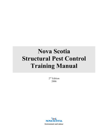
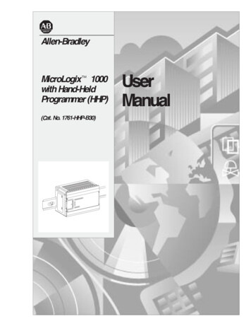
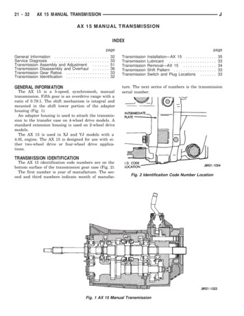
21 - 32AX 15 MANUAL TRANSMISSIONJAX 15 MANUAL TRANSMISSIONINDEXpageGeneral Information . . . . . . . . . . . . . . .Service Diagnosis . . . . . . . . . . . . . . . .Transmission Assembly and AdjustmentTransmission Disassembly and OverhaulTransmission Gear Ratios . . . . . . . . . .Transmission Identification . . . . . . . . . .323351363332GENERAL INFORMATIONThe AX 15 is a 5-speed, synchromesh, manualtransmission. Fifth gear is an overdrive range with aratio of 0.79:1. The shift mechanism is integral andmounted in the shift tower portion of the adapterhousing (Fig. 1).An adapter housing is used to attach the transmission to the transfer case on 4-wheel drive models. Astandard extension housing is used on 2-wheel drivemodels.The AX 15 is used in XJ and YJ models with a4.0L engine. The AX 15 is designed for use with either two-wheel drive or four-wheel drive ionTransmissionTransmissionInstallation—AX 15 . . . . .Lubricant . . . . . . . . . . . .Removal—AX 15 . . . . . .Shift Pattern . . . . . . . . . .Switch and Plug Locations.3533343333ture. The next series of numbers is the transmissionserial number.TRANSMISSION IDENTIFICATIONThe AX 15 identification code numbers are on thebottom surface of the transmission gear case (Fig. 2).The first number is year of manufacture. The second and third numbers indicate month of manufac-.Fig. 2 Identification Code Number LocationFig. 1 AX 15 Manual Transmission
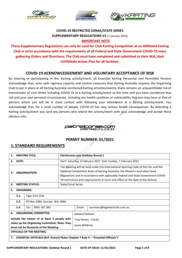
AX 15 MANUAL TRANSMISSIONJ21 - 33TRANSMISSION SHIFT PATTERNThe AX 15 shift pattern is shown in Figure 3. Firstand second and third and fourth gear ranges are inline for improved shifting. Fifth and reverse gearranges are also in line at the extreme right of thepattern (Fig. 3).The AX 15 is equipped with a reverse lockoutmechanism. The shift lever must be moved throughthe Neutral detent before making a shift to reverse.Fig. 5 Drain Plug And Backup Light Switch LocationTRANSMISSION GEAR RATIOSFig. 3 AX 15 Shift PatternTRANSMISSION LUBRICANTRecommended lubricant for AX 15 transmissions isMopar 75W-90, API Grade GL-5 gear lubricant, orequivalent.Correct lubricant refill or top-off level is to the bottom edge of the fill plug hole.Lubricant capacity is: 3.10 liters (3.27 qts.) in 4-wheel drive models. 3.15 liters (3.32 qts.) in 2-wheel drive models.TRANSMISSION SWITCH AND PLUG LOCATIONSThe fill plug is at the driver side of the gear case(Fig. 4).The drain plug and backup light switch are on thepassenger side of the gear case (Fig. 5).Fig. 4 Fill Plug LocationThe transmission gear ratios are as follows:First gear - 3.83:1Second gear - 2.33:1Third gear - 1.44:1Fourth gear - 1.00:1Fifth gear - 0.79:1Reverse - 4.22:1SERVICE DIAGNOSISLOW LUBRICANT LEVELA low transmission lubricant level is generally theresult of a leak, inadequate lubricant fill, or an incorrect lubricant level check.Leaks can occur at the mating surfaces of the gearcase, intermediate plate and adapter or extensionhousing, or from the front/rear seals. A suspectedleak could also be the result of an overfill condition.Leaks at the rear of the extension or adapter housing will be from the housing oil seals. Leaks at component mating surfaces will probably be the result ofinadequate sealer, gaps in the sealer, incorrect bolttightening, or use of a non-recommended sealer.A leak at the front of the transmission will be fromeither the front bearing retainer or retainer seal. Lubricant may be seen dripping from the clutch housing after extended operation. If the leak is severe, itmay also contaminate the clutch disc causing slip,grab and chatter.Transmissions filled from air or electrically powered lubricant containers can be underfilled. Thisgenerally happens when the container delivery mechanism is improperly calibrated. Always check the lubricant level after filling to avoid an under fillcondition.A correct lubricant level check can only be madewhen the vehicle is level; use a drive-on hoist to ensure this. Also allow the lubricant to settle for a
21 - 34AX 15 MANUAL TRANSMISSIONminute or so before checking. These recommendations will ensure an accurate check and avoid an under-or-overfill condition.HARD SHIFTINGHard shifting is usually caused by a low lubricantlevel, improper or contaminated lubricants, component damage, incorrect clutch adjustment, or by adamaged clutch pressure plate or disc.Substantial lubricant leaks can result in gear, shiftrail, synchro and bearing damage. If a leak goes undetected for an extended period, the first indicationsof a problem are usually hard shifting and noise.Incorrect or contaminated lubricants can also contribute to hard shifting. The consequence of usingnon-recommended lubricants is noise, excessive wear,internal bind and hard shifting.Improper clutch release is a frequent cause of hardshifting. Incorrect adjustment or a worn, damagedpressure plate or disc can cause incorrect release. Ifthe clutch problem is advanced, gear clash duringshifts can result.Worn or damaged synchro rings can cause gearclash when shifting into any forward gear. In somenew or rebuilt transmissions, new synchro rings maytend to stick slightly causing hard or noisy shifts. Inmost cases, this condition will decline as the ringswear-in.JTRANSMISSION NOISEMost manual transmissions make some noise during normal operation. Rotating gears can generate amild whine that may only be audible at extremespeeds.Severe, obviously audible transmission noise isgenerally the result of a lubricant problem. Insufficient, improper, or contaminated lubricant can promote rapid wear of gears, synchros, shift rails, forksand bearings. The overheating caused by a lubricantproblem, can also lead to gear breakage.TRANSMISSION REMOVAL—AX 15(1) Shift transmission into first or third gear.(2) Raise vehicle on a hoist.(3) Disconnect necessary exhaust system components.(4) Support transmission with adjustable jackstand.(5) Disconnect rear cushion and mounting bracketfrom transmission, or transfer case (Fig. 1).(6) On XJ, remove rear crossmember. On YJ, remove skid plate (Fig. 1).(7) Disconnect transmission shift linkage, speedometer cable, transfer case vacuum lines and clutchhydraulic lines.(8) Lower transmission-transfer case assembly nomore than 7.6 cm (3 in.) for access to shift lever.Fig. 1 Rear Mount Components (YJ Shown)
AX 15 MANUAL TRANSMISSIONJ21 - 35(9) Reach up and around transmission case andunseat shift lever dust boot from transmission shifttower (Fig. 2). Move boot upward on shift lever foraccess to lever retainer.(10) Disengage shift lever as follows:(a) Reach up and around transmission case andpress shift lever retainer downward with your fingers.(b) Turn retainer counterclockwise to release it.(c) Lift lever and retainer out of shift tower (Fig.2). It is not necessary to remove shift leverfrom floorpan boot. Simply leave lever inplace for later installation.Fig. 4 Timing Sensor LocationFig. 2 Removing/Installing Shift Lever(11) Mark front and rear propeller shafts for installation alignment (Fig. 3). Then remove bothshafts.Fig. 3 Marking Propeller Shaft And Axle Yoke(12) Remove crankshaft position/engine timing sensor (Fig. 4).(13) Disconnect transmission and transfer casevent hoses.(14) Remove slave cylinder from clutch housing.(15) Support transmission-transfer case assemblywith transmission jack. Secure assembly to jack withsafety chains.(16) Reposition adjustable jack stand under engine.Be sure to place wood block between jack and oilpan.(17) Remove clutch housing brace rod.(18) Remove clutch housing-to-engine bolts and remove transmission-transfer case assembly.(19) Remove bolts attaching transmission to transfer case and separate components.(20) Remove release bearing, fork and retainerclip.(21) Remove clutch housing from transmission.TRANSMISSION INSTALLATION—AX 15(1) Install clutch housing on transmission. Tightenhousing bolts to 37 Nzm (27 ft-lbs) torque.(2) Lubricate contact surfaces of release fork, leverand pivot ball stud. Then install bearing, fork andclip in clutch housing.(3) Mount transmission on transmission jack. Secure transmission with safety chains.(4) Lightly lubricate pilot bearing and transmission input shaft splines with Mopar high temperature grease.(5) Align transmission input shaft and clutch discsplines and install transmission.(6) Install and tighten clutch housing-to-enginebolts to 38 Nzm (28 ft. lbs.) torque. Be sure housingis properly seated on engine before tighteningbolts.(7) Lower transmission no more than 7.6 cm (3 in.)for access to the shift tower.(8) Reach up and around the transmission and insert shift lever in shift tower. Press lever retainerdownward and turn it clockwise to lock it in place.Then install lever dust boot on shift tower.(9) Connect engine timing sensor.
21 - 36AX 15 MANUAL TRANSMISSION(10) Remove jack from under transmission andmount transfer case on jack.(11) Align transfer case and transmission shaftsand install transfer case. Tighten transfer case-totransmission nuts/bolts to 35 Nzm (26 ft. lbs.) torque.(12) Move jack stand from under engine and reposition it under transmission. Then remove transmission jack.(13) Connect transfer case vacuum hoses and linkage. Check and adjust linkage if necessary.(14) Connect transmission and transfer case venthoses and backup light switch wires.(15) Install clutch sleeve cylinder.(16) Connect vehicle speed sensor and wires.(17) On XJ, install rear crossmember and attachcushion and bracket. Tighten crossmember-to-framebolts to 41 Nzm (30 ft. lbs.) torque. Tighten transmission-to-rear cushion and bracket bolts/nuts to 45 Nzm(33 ft. lbs.) torque.(18) On YJ, install rear cushion and bracket andskid plate. Tighten attaching bolts/nuts to indicatedtorque (Fig. 1).(19) Align and install front/rear propeller shafts.Tighten shaft U-joint clamp bolts to 19 Nzm (170 in.lbs.) torque.(20) On XJ, install skid plate if removed. Tightenbolts to 42 Nzm (31 ft. lbs.) torque. Tighten stud nutsto 17 Nzm (150 in. lbs.) torque.(21) Top off transmission and transfer lubricantlevels.(22) Remove supports and lower vehicle.J(3) Remove shift tower bolts and remove towerfrom adapter or extension housing (Fig. 2).Fig. 2 Shift Tower Removal/Installation(4) Remove gasket from shift tower (Fig. 3).TRANSMISSION DISASSEMBLY AND OVERHAULADAPTER/EXTENSION HOUSING REMOVAL(1) Remove release bearing, fork, retainer clip andclutch housing from transmission. Also remove shiftlever if not previously removed.(2) On 2-wheel drive models, remove extensionhousing seal (Fig. 1).Fig. 1 Removing Extension Housing SealFig. 3 Shift Tower Gasket Removal/Installation(5) Remove shift arm retainer bolt (Fig. 4).Fig. 4 Shift Arm Retainer Bolt Removal/Installation
AX 15 MANUAL TRANSMISSIONJ(6) Loosen and remove restrictor pins (Fig. 5).Fig. 5 Removing/Installing Restrictor Pins(7) Remove shift arm shaft plug (Fig. 6).21 - 37(9) Remove shift arm (Fig. 8).Fig. 8 Shift Arm Removal/Installation(10) Remove plug for reverse shift head lock ball.Plug is at right side of adapter housing near backuplight switch (Fig. 9).Fig. 6 Removing/Installing Shift Lever Shaft Plug(8) Remove shift arm shaft with large magnet (Fig.7).Fig. 7 Removing/Installing Shift Lever ShaftFig. 9 Removing/Installing Lock Ball Plug
21 - 38AX 15 MANUAL TRANSMISSIONJ(11) Remove lock ball spring with pencil magnet(Fig. 10).Fig. 10 Removing/Installing Lock Ball Spring(12) Remove shift head lock ball with pencil magnet (Fig. 11).Fig. 11 Removing/Installing Shift Head Lock Ball(13) Remove backup light switch from adapter/extension housing.(14) On 2-wheel drive models, remove distancesensor, speedometer adapter and driven gear if notremoved previously.(15) Remove adapter/extension housing bolts (Fig.12).Fig. 12 Adapter Housing Bolt Locations
AX 15 MANUAL TRANSMISSIONJ(16) Loosen adapter/extension housing with rubbermallet (Fig. 13).21 - 39GEAR CASE REMOVAL(1) Remove bearing retainer bolts and remove retainer (Fig. 16).Fig. 13 Loosening Adapter Housing(17) Remove housing after loosening it (Fig. 14)Fig. 16 Front Bearing Retainer Removal(2) Remove retainer oil seal with pry tool (Fig. 17).Fig. 14 Adapter Housing Removal(18) Remove adapter housing oil seal with pry tool(Fig. 15).Fig. 15 Removing Adapter Housing SealFig. 17 Front Bearing Retainer Seal Location(3) Remove input shaft bearing snap ring (Fig. 18).Fig. 18 Removing Input Shaft Bearing Snap Ring
21 - 40AX 15 MANUAL TRANSMISSION(4) Remove cluster gear front bearing snap ring(Fig. 19).J(7) On 2-wheel drive models, remove speedometergear snap ring and remove speedometer gear andspacer from output shaft.FIFTH GEAR AND SYNCHRO ASSEMBLYREMOVAL(1) Remove three lock ball plugs from intermediateplate (Fig. 22).Fig. 19 Removing Cluster Gear Front Bearing Snap Ring(5) Loosen gear case by tapping it away from intermediate plate with rubber mallet (Fig. 20).Fig. 22 Lock Ball Plug Locations(2) Remove three lock ball springs and lock ballsfrom intermediate plate with pencil magnet (Fig. 23).Fig. 20 Loosening Gear Case(6) Remove gear case from geartrain and intermediate plate (Fig. 21).Fig. 21 Gear Case RemovalFig. 23 Removing/Installing Lock Ball And Spring
AX 15 MANUAL TRANSMISSIONJ21 - 41Fig. 24 Mounting Intermediate Plate And Geartrain In Vise(3) Mount intermediate plate and geartrain assembly in vise as follows:(a) Insert two spare bolts in one bottom bolt holein intermediate plate. Insert bolts from oppositesides of plates (Fig. 24).(b) Install enough flat washers under each bolthead to prevent bolts from touching (Fig. 24).(c) Tape bolts and washers in place and mountintermediate plate in vise (Fig. 24).(d) Clamp vise jaws securely against bolt heads(Fig. 24). Do not clamp vise jaws on intermediate plate. Clamp only on bolt heads.(4) Remove fifth gear snap ring (Fig. 25). Retainsnap ring for assembly reference. It is a select fitcomponent.(5) Remove E-ring that secures reverse shift armto fork (Fig. 26).Fig. 26 Removing Reverse Shift Arm E-RingFig. 25 Fifth Gear Snap Ring Removal
21 - 42AX 15 MANUAL TRANSMISSIONJ(6) Remove bolts attaching reverse shift armbracket to intermediate plate. Then remove bracket(Fig. 27).Fig. 29 Removing Fifth Gear Fork Set ScrewFig. 27 Removing Reverse Shift Arm Bracket(7) Remove reverse shift arm and shoe (Fig. 28).Fig. 30 Removing Fifth Gear Shift ForkFig. 28 Removing Reverse Shift Arm And Shoe(8) Remove fifth gear shift fork set screw (Fig. 29).(9) Move fifth gear shift rail forward until it clearsshift fork.(10) Remove fifth gear shift fork from synchrosleeve (Fig. 30).(11) Remove reverse shift rail and reverse shifthead as assembly (Fig. 31).(12) Measure thrust clearance between counterfifth gear and thrust ring with feeler gauge. Clearance should be 0.10 - 0.40 mm (0.003 - 0.019 in.). Ifclearance exceeds limits, gear and/or ring will haveto be replaced.Fig. 31 Removing Reverse Shift Head And Rail
AX 15 MANUAL TRANSMISSIONJ(13) Loosen fifth spline gear with standard two-jawpuller (Fig. 32). Position puller jaws behind fifthcounter gear as shown.Fig. 32 Loosening Fifth Spline Gear(14) Remove fifth spline gear (Fig. 33).Fig. 33 Removing Fifth Spline Gear(15) Remove fifth gear synchro ring (Fig. 34).21 - 43(16) Remove fifth gear synchro and sleeve assembly (Fig. 35).Fig. 35 Removing Counter Fifth Gear And SynchroAssembly(17) Remove counter fifth gear thrust ring (Fig. 36).Fig. 36 Removing Fifth Gear Thrust Ring(18) Remove thrust ring lock ball with pencil magnet (Fig. 37).Fig. 34 Removing Fifth Gear Synchro RingFig. 37 Removing Thrust Ring Lock Ball
21 - 44AX 15 MANUAL TRANSMISSIONFig. 38 Removing Output Shaft Rear Bearing RetainerBoltsJFig. 39 Removing Output Shaft Rear Bearing Retainer(19) Remove bolts attaching output shaft rearbearing retainer to intermediate plate (Fig. 38).(20) Remove rear bearing retainer (Fig. 39).(21) Remove reverse gear and shaft (Fig. 40).SHIFT RAIL AND FORK REMOVALThere are a total of five shift rails in the AX 15transmission. The 1-2, 3-4, fifth gear and front reverse shift rails are shown in Figure 41.Two shift rails are used for reverse gear range. Thefront reverse rail is at the forward side of the intermediate plate (Fig. 41). The short rear reverse railand reverse shift head are at the rear side of the intermediate plate.It is not necessary to remove the shift rails ifthey do not require service during overhaul.Fig. 40 Removing Reverse Idler Gear And ShaftFig. 41 Shift Rail Identification
AX 15 MANUAL TRANSMISSIONJ21 - 45Only the shift forks need be removed for accessto the transmission shafts and gears.(1) Remove fifth gear shift rail (Fig. 41). Catchlock ball in your hand as rail comes out of intermediate plate.(2) Remove 1-2 and 3-4 shift rail C-rings with twoscrewdrivers of equal size and length (Fig. 42).Fig. 44 Removing 3-4 Shift Rail(5) Remove 3-4 shift rail interlock plug from intermediate plate with magnet (Fig. 45).Fig. 42 Removing Shift Rail C-Rings(3) Remove shift fork set screws (Fig. 43).Fig. 45 Removing 3-4 Shift Rail Interlock Plug(6) Remove 1-2 shift rail from shift fork and intermediate plate (Fig. 46).Fig. 43 Removing Shift Fork Set Screws(4) Remove 3-4 shift rail from shift fork and intermediate plate (Fig. 44).Fig. 46 Removing 1-2 Shift Rail
21 - 46AX 15 MANUAL TRANSMISSION(7) Remove 1-2 shift rail interlock pin from shiftrail (Fig. 47).J(10) Remove 3-4 shift fork (Fig. 50).(11) Remove 1-2 shift fork (Fig. 50).Fig. 47 Removing 1-2 Shift Rail Interlock Pin(8) Remove 1-2 shift rail interlock plug from intermediate plate (Fig. 48).Fig. 50 Shift Fork RemovalFig. 48 Removing 1-2 Shift Rail Interlock Plug(9) Lift reverse shift fork upward and remove fifthgear shift rail lock ball (Fig. 49).Fig. 49 Removing Fifth Gear Shift Rail Lock Ball(12) Remove reverse shift rail C-ring with twoequal length and size screwdrivers (Fig. 51).(13) Remove reverse shift rail and fork (Fig. 52).(14) Remove interlock pin from reverse shift rail(Fig. 53).(15) Position shift rails, shift forks, lock balls, interlock plugs and interlock pins on the workbench inorder of removal. This will help in identifying components during inspection and assembly.
AX 15 MANUAL TRANSMISSIONJ21 - 47Fig. 53 Removing Reverse Shift Rail Interlock PinFig. 51 Removing Reverse Shift Rail C-RingFig. 52 Removing Reverse Shift Rail And ForkFig. 54 Removing Bearing Snap RingsOUTPUT SHAFT AND CLUSTER GEARREMOVAL(1) Remove output shaft rear bearing snap ring(Fig. 54).(2) Remove cluster gear rear bearing snap ring(Fig. 54).(3) Tap end of output shaft with mallet to unseatand start rear bearing out of intermediate plate (Fig.55).(4) Remove output shaft by rocking it lightly untilrear bearing comes out of intermediate plate (Fig.56).(5) Remove cluster gear by pulling it straight outof rear bearing (Fig. 57).(6) Remove cluster gear rear bearing from intermediate plate (Fig. 58).(7) Remove input shaft from output shaft (Fig. 59).(8) Remove output shaft pilot bearing from inputshaft (Fig. 60).(9) Remove synchro ring from input shaft (Fig. 61).
21 - 48AX 15 MANUAL TRANSMISSIONJFig. 55 Unseating Output Shaft Rear BearingFig. 58 Removing Cluster Gear Rear BearingFig. 56 Input/Output Shaft Assembly RemovalFig. 59 Input Shaft RemovalFig. 57 Cluster Gear RemovalFig. 60 Removing Input Shaft Pilot Bearing(10) Remove bearing snap ring and press bearingoff input shaft (Fig. 61). First gear clearance should be 0.10 - 0.40 mm(0.003 - 0.0197 in). Second—third gear clearance should be 0.10 - 0.30mm (0.003 - 0.0118 in.).(2) If first gear thrust clearance is incorrect, replacegear and thrust washer. If second or third gear clearance is incorrect, either gear and bearing, or out-OUTPUT SHAFT DISASSEMBLY(1) Measure thrust clearance of output shaft first,second and third gears with feeler gauge (Fig. 62).
AX 15 MANUAL TRANSMISSIONJ21 - 49Fig. 61 Input Shaft Componentsput shaft flange is worn. Refer to output shaftinspection in Cleaning and Inspection section.(3) Press fifth gear and rear bearing off rear ofoutput shaft.(4) Remove thrust washer, pin, and first gear andbearing (Fig. 62).(5) Remove first/reverse hub snap ring (Fig. 63).(6) Remove synchro ring.(7) Press reverse gear and first/reverse hub offshaft as assembly.Fig. 62 Checking Output Shaft Gear Thrust Clearance(8) Remove remaining synchro ring and secondgear and bearing (Fig. 63).(9) Remove snap ring at front of output shaft (Fig.63).Fig. 63 Output Shaft And Gears
21 - 50AX 15 MANUAL TRANSMISSIONJ(10) Press 3-4 hub and sleeve off output shaft asassembly (Fig. 63).(11) Remove synchro ring.(12) Remove third gear and needle bearing (Fig. 63).TRANSMISSION CLEANING AND INSPECTIONClean the transmission components in solvent. Drythe cases, gears, shift mechanism and shafts with compressed air. Dry the bearings with clean, dry shoptowels only. Never use compressed air on the bearings. This could damage the bearing rollers.Replace components that are obviously worn,cracked, chipped or damaged in any way.Inspect the transmission case. Replace the case ifcracked or porous or if any of the bearing and gearbores are damaged.Output Shaft InspectionMeasure thickness of the output shaft flange witha micrometer (Fig. 64). Minimum allowable flangethickness is 4.70 mm (0.185 in).If shaft flange thickness is OK but previouslymeasured second/third gear thrust clearancewas incorrect (Fig. 62), replace the necessarygear and needle bearing as an assembly.Check diameter of the first, second and third gearbearing surfaces of the output shaft (Fig. 64). Minimum allowable diameters are: 38.86 mm (1.529 in.) for first gear surface 46.86 mm (1.844 in.) for second gear surface 37.86 mm (1.490 in.) for third gear surfaceCheck output shaft runout with V-blocks and a dialindicator (Fig. 64). Maximum allowable runout is0.06 mm (0.0024 in.).Replace the output shaft if any surface measuredfails to meet stated tolerance.Fig. 64 Checking Output Shaft TolerancesCluster Gear InspectionInspect the cluster gear teeth. Replace the gear ifany teeth are worn or damaged or if the bearing surfaces are damaged.Check diameter of the cluster gear journal with amicrometer (Fig. 65). Minimum allowable diameteris 27.860 mm (1.096 in.).Check condition of the cluster gear front bearing.Replace the bearing if worn, noisy, or damaged.GEAR AND SYNCHRO INSPECTIONInstall the synchro rings on their respective gears.Rotate each ring on the gear and note synchro action. Replace any synchro ring that exhibits a lack ofbraking action or binds on the gear. Also replace anyring that is worn or has chipped or broken teeth.Measure end clearance between the synchro ringand the gear with a feeler gauge (Fig. 66). Clearanceshould be 0.06 mm - 1.6 mm (0.024 - 0.063 in.).Fig. 65 Checking Cluster Gear Journal DiameterInstall the needle bearings in the first, second andthird gears. Then install the gears on the outputshaft and check shaft-to-gear clearance with a dialindicator (Fig. 67).
AX 15 MANUAL TRANSMISSIONJFig. 66 Checking Synchro Ring End Clearance21 - 51Fig. 68 Checking Shift Fork-To-Sleeve ClearanceMaximum allowable clearance is 0.16 mm (0.0063in.). If any gear exhibits excessive clearance, replacethe gear and needle bearing.Fig. 69 Reverse Idler Gear BushingFig. 67 Checking Gear-To-Shaft ClearanceCheck clearance between the shift forks and synchro sleeves with a feeler gauge (Fig. 68). Clearanceshould not exceed 1.0 mm (0.039 in.). Replace thesynchro sleeve (and matching hub) if clearance exceeds the stated limit.Check condition of the reverse idler gear bushing(Fig. 69). Replace the gear if the bushing is damaged orworn.Gear Case, Housing And Intermediate PlateClean the case, housing and plate with solvent anddry with compressed air. Replace any component thatis cracked, warped or damaged in any way.Inspect the threads in the case, housing and plate.Minor thread damage can be repaired with steel threadinserts if necessary. However, do not attempt to repairif the cracks are evident around any threaded hole.Inspect the reverse pin in the adapter/extensionhousing. Replace the pin if worn or damaged. Referto the replacement procedure in the TransmissionAssembly section.TRANSMISSION ASSEMBLY AND ADJUSTMENTLubricate the transmission components with Mopar75W-90 gear lubricant during assembly. Use petroleum jelly to lubricate seal lips and/or hold parts inplace during installation.
21 - 52AX 15 MANUAL TRANSMISSIONFRONT BEARING, SEAL AND PININSTALLATION(1) Press front bearing on input shaft. Then securebearing with thickest snap ring that will fit in shaftgroove (Fig. 70).J(3) Install new oil seals in front bearing retainer andadapter housing (Fig. 72). Installation depth for bearingretainer seal is 10.5 - 11.5 mm (0.414 - 0.453 in.).Fig. 70 Selecting Input Shaft Front Bearing SnapRing(2) Press front bearing on cluster gear. Then secure bearing with thickest snap ring that will fit inring groove on gear (Fig. 71).Fig. 72 Oil Seal Installation(4) Install reverse shaft and shaft retaining pin inadapter housing. Then install access hole plug withtorx bit (Fig. 73).Fig. 71 Selecting Cluster Gear Front Bearing SnapRingFig. 73 Installing Reverse Shaft Pin
AX 15 MANUAL TRANSMISSIONJ21 - 53(5) Lubricate reverse shaft and gear componentswith Mopar 75W-90 gear lubricant.OUTPUT SHAFT ASSEMBLY(1) Lubricate output shaft journals, gears and needle bearings with Mopar 75W-90 gear lubricant.(2) Install third gear and needle bearing on shaft(Fig. 63)(3) Install synchro ring on third gear (Fig. 63).(4) Assemble 1-2 and 3-4 synchro hubs and sleeves(Fig.74).Fig. 76 Installing 3-4 Synchro Hub Snap RingFig. 74 Synchro Sleeve And Hub Identification(5) Install inserts and springs in synchro sleeves.Position open ends of springs 180 apart as shown(Fig. 75).Fig. 77 Checking Third Gear ClearanceFig. 75 Insert Spring Position(6) Install 3-4 synchro hub and sleeve on outputshaft. Press hub onto shaft if necessary.(7) Install 3-4 synchro hub snap ring (Fig. 76). Usethickest snap ring that will fit in shaft groove.(8) Verify third gear thrust clearance with feelergauge (Fig. 56). Clearance should be 0.10 - 0.25 mm(0.004 - 0.010 in.).(9) Lubricate remaining output shaft gears andbearings with gear lubricant.(10) Install second gear and needle bearing onshaft (Fig. 78).(11) Install synchro ring on second gear (Fig. 78).(12) Assemble first/reverse hub, insert springs, inserts, reverse gear and 1-2 sleeve (Fig. 78). Be surespring ends are 180 apart. Note that splines inhub bore are chamfered on one side. Install hubso chamfered side faces front of output shaft.(13) Press assembled hub and sleeve on outputshaft.(14) Install selective snap ring (Fig. 78). Use thickest snap ring that will fit in output shaft groove.(15) Install synchro ring on first gear (Fig. 79).
21 - 54AX 15 MANUAL TRANSMISSIONJFig. 78 Second Gear And Synchro Assembly(16) Install first gear spacer on shaft and againstselective fit snap ring (Fig. 79).(17) Install first gear and needle bearing (Fig. 79)on output shaft.(18) Install locating pin and thrust washer onshaft (Fig. 79).Fig. 80 Selecting Fifth Gear Snap Ring(22) Lubricate input shaft pilot bearing with petroleum jelly and install bearing in shaft (Fig. 60).(23) Install input shaft on output shaft (Fig. 59). Besure output shaft hub is fully seated in pilot bearing.Fig. 79 First And Fifth Gear Components(19) Press rear bearing on shaft. Position bearingsnap ring groove so it is closest to end of output shaft.(20) Check first and second gear thrust clearancewith feeler gauge (Fig. 62). First gear clearance should be 0.10 - 0.40 mm(0.003 - 0.0197 in.) Second gear clearance should be 0.10 - 0.30 mm(0.003 - 0.0118 in.)(21) Press fifth gear onto output shaft. Then installselect fit snap ring (Fig. 80). Use thickest snap ringthat will fit in shaft groove.OUTPUT SHAFT AND CLUSTER GEARINSTALLATION(1) Mount intermediate plate in vise (Fig. 24).(2) Lubricate cluster gear journal and rear bearingwith petroleum jelly or gear lubricant.(3) Install cluster gear rear bearing in intermediate plate (Fig. 81). Be sure snap ring groove in bearing is rearward as shown.(4) Start cluster gear into bearing (Fig. 57). Thenhold bearing and push gear into place. Use plastic orrawhide mallet to seat bearing if necessary.(5) Start output shaft rear bearing in intermediateplate. Push shaft rearward and tap intermediateplate with mallet to seat bearing.
AX 15 MANUAL TRANSMISSIONJ21 - 55(7) Install reverse idler gear and shaft (Fig. 83).Fig. 81 Installing Cluster Gear Rear Bearing(6) Install snap rings on cluster and output shaftrear bearings only (Fig. 82). Do not install frontbearing snap rings at this time.Fig. 83 Installing Reverse Idler Gear And Shaft(8) Position rear bearing retainer over output shaftand rear bearing. Be sure bearing retainer tab isengaged in reverse idler shaft notch (Fig. 84).(9) Install and tighten rear bearing retainer boltsto 18 Nzm (13 ft-lbs).Fig. 82 Installing Rear Bearing Snap RingsFig. 84 Installing Rear Bearing Retainer
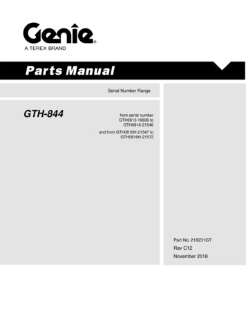
21 - 56AX 15 MANUAL TRANSMISSIONJFig. 85 Shift Rail Ball-Plug-Pin PositionSHIFT RAIL AND FORK INSTALLATIONThe shift rail interlock pins, balls and plugs mustbe installed in the correct sequence for proper shifting. Refer to the installation diagram (Fig. 85) during assembly.Coat the intermediate plate shift rail bores andthe interlock balls, pins and plugs with a heavycoating of petroleum jelly before assembly. Thejelly will hold the interlock components in placemaking installation easier. Use a pencil magnetto hold and insert the interlocks. Then use asmall screwdriver to push the interlock components into place.(1) Coat reverse rail interlock pin with petroleumjelly and install pin in rail (Fig. 86).Fig. 86 Installing Reverse Shift Rail Interlock Pin
AX 15 MANUAL TRANSMISSIONJ21 - 57(2) Install reverse shift rail in intermediate plate(Fig. 87).(3) Install reverse shi
TRANSMISSION REMOVAL—AX 15 (1) Shift transmission into first or third gear. (2) Raise vehicle on a hoist. (3) Disconnect necessary exhaust system compo-nents. (4) Support transmission with adjustable jack stand. (5) Disconnect rear cushion and mounting bracket from transmission, or transfer case (Fig. 1). (6) On XJ, remove rear crossmember .