Transcription
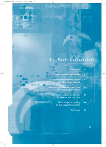
Chap4-30-4521/06/029:57Page 30 4 Fault CalculationsIntroduction4.1Three phase fault calculations4.2Symmetrical component analysisof a three-phase network4.3Equations and network connectionsfor various types of faults4.4Current and voltage distributionin a system due to a fault4.5Effect of system earthingon zero sequence quantities4.6References4.7
Chap4-30-4521/06/029:57Page 31 4 Fault Calculations4.1 INTRODUCTIONA power system is normally treated as a balancedsymmetrical three-phase network. When a fault occurs,the symmetry is normally upset, resulting in unbalancedcurrents and voltages appearing in the network. The onlyexception is the three-phase fault, which, because itinvolves all three phases equally at the same location, isdescribed as a symmetrical fault. By using symmetricalcomponent analysis and replacing the normal systemsources by a source at the fault location, it is possible toanalyse these fault conditions.For the correct application of protection equipment, it isessential to know the fault current distributionthroughout the system and the voltages in differentparts of the system due to the fault. Further, boundaryvalues of current at any relaying point must be known ifthe fault is to be cleared with discrimination. Theinformation normally required for each kind of fault ateach relaying point is:i. maximum fault currentii. minimum fault currentiii. maximum through fault currentTo obtain the above information, the limits of stablegeneration and possible operating conditions, includingthe method of system earthing, must be known. Faultsare always assumed to be through zero fault impedance.4 . 2 T H R E E - P H A S E F A U LT C A L C U L AT I O N SThree-phase faults are unique in that they are balanced,that is, symmetrical in the three phases, and can becalculated from the single-phase impedance diagramand the operating conditions existing prior to the fault.A fault condition is a sudden abnormal alteration to thenormal circuit arrangement. The circuit quantities,current and voltage, will alter, and the circuit will passthrough a transient state to a steady state. In thetransient state, the initial magnitude of the fault currentwill depend upon the point on the voltage wave at whichthe fault occurs. The decay of the transient condition,until it merges into steady state, is a function of theparameters of the circuit elements. The transient currentmay be regarded as a d.c. exponential currentNetwork Protection & Automation Guide 31
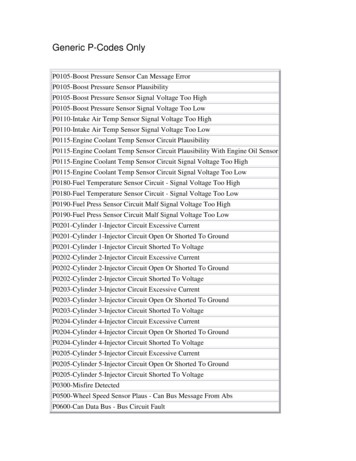
Chap4-30-4521/06/029:57Page 32superimposed on the symmetrical steady state faultcurrent. In a.c. machines, owing to armature reaction,the machine reactances pass through 'sub transient' and'transient' stages before reaching their steady statesynchronous values. For this reason, the resultant faultcurrent during the transient period, from fault inceptionto steady state also depends on the location of the faultin the network relative to that of the rotating plant.be added to the currents circulating in the system due tothe fault, to give the total current in any branch of thesystem at the time of fault inception. However, in mostproblems, the load current is small in comparison to thefault current and is usually ignored.In a practical power system, the system regulation issuch that the load voltage at any point in the system iswithin 10% of the declared open-circuit voltage at thatpoint. For this reason, it is usual to regard the pre-faultvoltage at the fault as being the open-circuit voltage,and this assumption is also made in a number of thestandards dealing with fault level calculations.In a system containing many voltage sources, or havinga complex network arrangement, it is tedious to use thenormal system voltage sources to evaluate the faultcurrent in the faulty branch or to calculate the faultcurrent distribution in the system. A more practicalmethod [4.1] is to replace the system voltages by a singledriving voltage at the fault point. This driving voltage isthe voltage existing at the fault point before the faultoccurs.For an example of practical three-phase faultcalculations, consider a fault at A in Figure 3.9. With thenetwork reduced as shown in Figure 4.2, the load voltageat A before the fault occurs is:Consider the circuit given in Figure 4.1 where the driving——voltages are E and E’ , the impedances on either side of——fault point F are Z1’ and Z1’’ , and the current through—point F before the fault occurs is I .Figure 4.2:2.5 Ω1.55 Ω0.39 ΩAB1.2 ΩFigure 4.1:0.99E ''0.97E 'Z '1Z ''1FFa u l t C a l c u l a t i o n sI 4 NE'E''VFigure 4.2: Reduction of typicalpower system network———V 0.97 E’ - 1.55 INFigure 4.1: Network with fault at F—The voltage V at F before fault inception is:— — —— — ——V E - I Z‘ E’’ I Z’’—After the fault the voltage V is zero. Hence, the change—in voltage is - V . Because of the fault, the change in thecurrent flowing into the network from F is:( 1.2 2.5 V 0.99 E '' 0.39 I 2.5 1.2 ——For practical working conditions, E’ 〉〉〉1.55 I and—— — ——E’’ 〉〉〉1.207 I . Hence E’ E’’ V.——Replacing the driving voltages E’ and E’’ by the load—voltage V between A and N modifies the circuit as shownin Figure 4.3(a).The node A is the junction of three branches. In practice,the node would be a busbar, and the branches arefeeders radiating from the bus via circuit breakers, asshown in Figure 4.3(b). There are two possible locationsfor a fault at A; the busbar side of the breakers or theline side of the breakers. In this example, it is assumedthat the fault is at X, and it is required to calculate thecurrent flowing from the bus to X.)Z1' Z1''V VZ1Z1' Z1''and, since no current was flowing into the network fromF prior to the fault, the fault current flowing from thenetwork into the fault is: I IfZ1' Z1'' )( I VThe network viewed from AN has a driving pointimpedance Z1 0.68 ohms.Z1' Z1''By applying the principle of superposition, the loadcurrents circulating in the system prior to the fault mayThe current in the fault is 32 VZ1 .Network Protection & Automation Guide
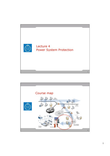
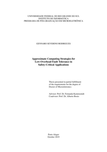
Chap4-30-4521/06/029:57Page 33Let this current be 1.0 per unit. It is now necessary tofind the fault current distribution in the various branchesof the network and in particular the current flowing fromA to X on the assumption that a relay at X is to detectthe fault condition. The equivalent impedances viewedfrom either side of the fault are shown in Figure 4.4(a).Therefore, current in 2.5 ohm branch1.2 0.563 0.183 p.u.3.7and the current in 1.2 ohm branch 2.5 0.563 0.38 p.u.3.7Total current entering X from the left, that is, from A toX, is 0.437 0.183 0.62 p.u. and from B to X is0.38p.u. The equivalent network as viewed from therelay is as shown in Figure 4.4(b). The impedances oneither side are: 2.5ΩFigure 4.30.39Ω1.55ΩFigure 4.4AB1.2ΩVN(a) Three - phase fault diagram for a fault at node A0.68/0.62 1.1 ohmsandBusbarCircuit breaker0.68/0.38 1.79 ohmsThe circuit of Figure 4.4 (b) has been included becausethe Protection Engineer is interested in these equivalentparameters when applying certain types of protectionrelay.AX(b) Typical physical arrangement of node A with a fault shown at X1.55ΩA1.21ΩVN(a) Impedance viewed from node A1.1ΩX1.79ΩVN(b) Equivalent impedances viewed from node XFigure 4.4: Impedances viewed from faultThe Protection Engineer is interested in a wider variety offaults than just a three-phase fault. The most commonfault is a single-phase to earth fault, which, in LVsystems, can produce a higher fault current than a threephase fault. Similarly, because protection is expected tooperate correctly for all types of fault, it may benecessary to consider the fault currents due to manydifferent types of fault. Since the three-phase fault isunique in being a balanced fault, a method of analysisthat is applicable to unbalanced faults is required. It canbe shown [4.2] that, by applying the 'Principle ofSuperposition', any general three-phase system ofvectors may be replaced by three sets of balanced(symmetrical) vectors; two sets are three-phase buthaving opposite phase rotation and one set is co-phasal.These vector sets are described as the positive, negativeand zero sequence sets respectively.The equations between phase and sequence voltages aregiven below: E b a 2 E1 aE 2 E 0 E c aE1 a 2 E 2 E 0 E a E1 E 2 E 0The currents from Figure 4.4(a) are as follows:From the right: 1.55 0.563 p.u.2.76From the left: 1.21 0.437 p.u.2.76There is a parallel branch to the right of ANetwork Protection & Automation Guide 33 Equation 4.1Fa u l t C a l c u l a t i o n s4 . 3 S Y M M E T R I C A L C O M P O N E N T A N A LY S I SOF A THREE-PHASE NETWORKFigure 4.3: Network with fault at node A 4
Chap4-30-4521/06/029:57Page 34((—fault branch changes from 0 to I and the positive— —sequence voltage across the branch changes from V to V1 ;replacing the fault branch by a source equal to the changein voltage and short-circuiting all normal driving voltages—in the system results in a current I flowing into thesystem, and:))1 E1 E a aE b a 2 E c 3 12E2 E a a E b aE c 3 1E0 Ea Eb Ec 3 () Equation 4.2 I where all quantities are referred to the reference phaseA. A similar set of equations can be written for phaseand sequence currents. Figure 4.5 illustrates theresolution of a system of unbalanced vectors.Figure 4.5EoE2EaEcaE1E1a2E1EbaE2Fa u l t C a l c u l a t i o n sEo 4 Figure 4.5: Resolution of a systemof unbalanced vectors1Z1 Equation 4.3—where Z1 is the positive sequence impedance of thesystem viewed from the fault. As before the fault nocurrent was flowing from the fault into the system, it—follows that I1 , the fault current flowing from the—system into the fault must equal - I . Therefore:— ——— Equation 4.4V1 V - I1 Z1Eoa2E2(V V )is the relationship between positive sequence currentsand voltages in the fault branch during a fault.In Figure 4.6, which represents a simple system, the— —— —— —voltage drops I1’ Z1’ and I1’ Z1’’ are equal to ( V - V1 )——where the currents I1’ and I1’’ enter the fault from the——left and right respectively and impedances Z1’ and Z1’’are the total system impedances viewed from either side—of the fault branch. The voltage V is equal to the opencircuit voltage in the system, and it has been shown that— — —V E E ’’ (see Section 3.7). So the positive sequencevoltages in the system due to the fault are greatest at thesource, as shown in the gradient diagram, Figure 4.6(b).When a fault occurs in a power system, the phaseimpedances are no longer identical (except in the case ofthree-phase faults) and the resulting currents andvoltages are unbalanced, the point of greatest unbalancebeing at the fault point. It has been shown in Chapter 3that the fault may be studied by short-circuiting allnormal driving voltages in the system and replacing thefault connection by a source whose driving voltage isequal to the pre-fault voltage at the fault point. Hence,the system impedances remain symmetrical, viewed fromthe fault, and the fault point may now be regarded as thepoint of injection of unbalanced voltages and currentsinto the system.XFigure 4.6 Z '1ZS1Z ''1FI '1I ''1I1Z '1V1E'E'N(a) System diagramI '1NXI '1 Z '1VThis is a most important approach in defining the faultconditions since it allows the system to be representedby sequence networks [4.3] using the method ofsymmetrical components.V '1 I '1 Z '1FV1N'(b) Gradient diagramFigure 4.6: Fault at F:Positive sequence diagrams4.3.1 Positive Sequence NetworkDuring normal balanced system conditions, only positivesequence currents and voltages can exist in the system,and therefore the normal system impedance network is apositive sequence network.4.3.2 Negative Sequence NetworkWhen a fault occurs in a power system, the current in theIf no negative sequence quantities are present in theIf only positive sequence quantities appear in a powersystem under normal conditions, then negative sequencequantities can only exist during an unbalanced fault. 34 Network Protection & Automation Guide
21/06/029:57Page 35fault branch prior to the fault, then, when a fault occurs,——the change in voltage is V2 , and the resulting current I2flowing from the network into the fault is:I2 V2Z24.4 EQUATIONS AND NETWORK CONNECTIONSFOR VARIOUS TYPES OF FAULTSThe most important types of faults are as follows:a. single-phase to earth Equation 4.5b. phase to phaseThe impedances in the negative sequence network aregenerally the same as those in the positive sequence——network. In machines Z1 Z2 , but the difference isgenerally ignored, particularly in large networks.c. phase-phase-earthd. three-phase (with or without earth)The above faults are described as single shunt faultsbecause they occur at one location and involve aconnection between one phase and another or to earth.The negative sequence diagrams, shown in Figure 4.7, aresimilar to the positive sequence diagrams, with twoimportant differences; no driving voltages exist before—the fault and the negative sequence voltage V2 isgreatest at the fault point.Figure 4.7In addition, the Protection Engineer often studies twoother types of fault:e. single-phase open circuitf. cross-country faultXBy determining the currents and voltages at the faultpoint, it is possible to define the fault and connect thesequence networks to represent the fault condition.From the initial equations and the network diagram, thenature of the fault currents and voltages in differentbranches of the system can be determined. Z '1 I'2 F I''2 Z ''1ZS1I2Z '1V2For shunt faults of zero impedance, and neglecting loadcurrent, the equations defining each fault (using phaseneutral values) can be written down as follows:N(a) Negative sequence networkFXa. Single-phase-earth (A-E)V2Ib 0 Ic 0 V a 0 V2 I '2 Z '1N(b) Gradient diagramFigure 4.7: Fault at F:Negative sequence diagramb. Phase-phase (B-C) Ib Ic V b V c c. Phase-phase-earth (B-C-E)Ia 04.3.3 Zero Sequence NetworkThe zero sequence current and voltage relationshipsduring a fault condition are the same as those in thenegative sequence network. Hence:———V0 - I0 Z0 Equation 4.6Ia 0 Vb 0 V c 0 d. Three-phase (A-B-C or A-B-C-E)Also, the zero sequence diagram is that of Figure 4.7,——substituting I0 for I2 , and so on.The currents and voltages in the zero sequence networkare co-phasal, that is, all the same phase. For zerosequence currents to flow in a system there must be areturn connection through either a neutral conductor orthe general mass of earth. Note must be taken of thisfact when determining zero sequence equivalent circuits.———Further, in general Z1 Z0 and the value of Z0 variesaccording to the type of plant, the winding arrangementand the method of earthing.Network Protection & Automation Guide Equation 4.7 Equation 4.8 Equation 4.9Ia Ib Ic 0 Va Vb Vb Vc Equation 4.10It should be noted from the above that for any type offault there are three equations that define the faultconditions. 35 Fa u l t C a l c u l a t i o n sChap4-30-45 4
Chap4-30-4521/06/029:57Page 36— —— ——V - I1 Z1 I2 Z2—and substituting for I2 from Equation 4.15:— — — —V I1 ( Z1 Z2 ) Equation 4.17When there is a fault impedance, this must be taken intoaccount when writing down the equations. For example,with a single-phase-earth fault through fault impedance—Zf , Equations 4.7 are re-written: Ic 0 V a I a Z f The constraints imposed by Equations 4.15 and 4.17indicate that there is no zero sequence networkconnection in the equivalent circuit and that the positiveand negative sequence networks are connected inparallel. Figure 4.9 shows the defining and equivalentcircuits satisfying the above equations.Ib 0 Equation 4.11Figure IbN1IcIb 0Ic 0Va 0(a) Definition of faultVaFFigure4.9AZ0N0Z2N2VZ0N0Ia 0Ib -IcVb -Vc(b) Equivalent circuit(a) Definition of faultFigure 4.8: Single-phase-earth fault at F(b) Equivalent circuitFa u l t C a l c u l a t i o n sFigure 4.9: Phase-Phase fault at F 4 4.4.1 Single-phase-earth Fault (A-E)4.4.3 Phase-phase-earth Fault (B-C-E)Consider a fault defined by Equations 4.7 and by Figure4.8(a).Converting Equations 4.7 into sequencequantities by using Equations 4.1 and 4.2, then:Again, from Equation 4.9 and Equations 4.1 and 4.2:— —— Equation 4.18I1 -( I2 Io )1I1 I 2 I o I a Equation 4.123——— Equation 4.13V1 - ( V2 V0 )— ——Substituting for V1 , V2 and V0 in Equation 4.13 fromEquations 4.4, 4.5 and 4.6:— —— —— ——V - I1 Z1 I2 Z2 I0 Z0— — —but, from Equation 4.12, I1 I2 I0 , therefore:— — — — —V I1 ( Z1 Z2 Z3 ) Equation 4.14— — — Equation 4.19V1 V2 V0——Substituting for V2 and V0 using network Equations 4.5and 4.6:—— ——I2 Z2 I0 Z0The constraints imposed by Equations 4.12 and 4.14indicate that the equivalent circuit for the fault isobtained by connecting the sequence networks in series,as shown in Figure 4.8(b).Z 0 I1 Equation 4.21Z0 Z 2——Now equating V1 and V2 and using Equation 4.4 gives:— ————V - I1 Z1 - I2 Z24.4.2 Phase-phase Fault (B-C)orandthus, using Equation 4.18:I0 Z 2 I1Z0 Z 2 Equation 4.20I2 — —— ——V I1 Z1 - I2 Z2—Substituting for I2 from Equation 4.21:From Equation 4.8 and using Equations 4.1 and 4.2:—— Equation 4.15I1 - I2—I0 0——V1 V 2 Equation 4.16 Z0 Z 2 V Z1 I1Z 0 Z 2 orFrom network Equations 4.4 and 4.5, Equation 4.16 canbe re-written:— —— —— ——V - I1 Z1 I2 Z2 I0 Z0I1 V 36 (Z0 Z2)Z1 Z 0 Z1 Z 2 Z 0 Z 2 Equation 4.22Network Protection & Automation Guide
Chap4-30-4521/06/029:57Page 37From the above equations it follows that connecting thethree sequence networks in parallel as shown in Figure4.10(b) may represent a phase-phase-earth fault.Hence, from Equations 4.2,V0 1/3 VaV1 1/3 VaVbBZ1VcCF2V2 1/3 VaF0Z2Z0N2IbN0N1 VIcIa 0Vb 0Vc 0(a) Definition of fault(b) Equivalent circuitand therefore:V1 V 2 V0 1 3 V a I a I1 I 2 I 0 0 Equation 4.28From Equations 4.28, it can be concluded that thesequence networks are connected in parallel, as shown inFigure 4.12(b).Figure 4.10: Phase-phase-earth fault at FVaP4.4.4 Three-phase Fault (A-B-C or A-B-C-E)VcAssuming that the fault includes earth, then, fromEquations 4.10 and 4.1, 4.2, it follows that:V0 V aV1 V 2and 0 QVa'Ib Vb'νb I Vc'cνc(a) Circuit diagramI1N1 Equation 4.23— Equation 4.24I0 0—Substituting V2 0 in Equation 4.5 gives:— Equation 4.25I2 0—and substituting V1 0 in Equation 4.4:— ——0 V1 - I1 Z1or— —— Equation 4.26V I1 Z1—Further, since from Equation 4.24 Io 0 , it follows from——Equation 4.6 that Vo is zero when Zo is finite. Theequivalent sequence connections for a three-phase faultare shown in Figure 4.11.νa 2Q2I0N0ZeroSequenceNetworkP0ν0Q0(b) Equivalent circuitFigure 4.12: Open circuit on phase A4.4.6 Cross-country FaultsA cross-country fault is one where there are two faultsaffecting the same circuit, but in different locations andpossibly involving different phases. Figure 4.13(a)illustrates this.The constraints expressed in terms of sequencequantities are as follows:a) At point FAVaFF2F1I b I c 0 Va 0 F0VbBZ1VcCFigure 4.11 IcZ2N2IbIaN1Z0N0Therefore:VI a1 I a 2 I a 0Ia Ib Ic 0Va Vb Vc 0(a) Definition of fault V a1 V a 2 V a 0 0 I ' a I ' c 0 V 'b 0 4.4.5 Single-phase Open Circuit FaultThe single-phase open circuit fault is showndiagrammatically in Figure 4.12(a). At the fault point,the boundary conditions are: Equation 4.31and therefore:I ’b1 I ’b2 I ’b0 Equation 4.32To solve, it is necessary to convert the currents andvoltages at point F ’ to the sequence currents in thesame phase as those at point F. From Equation 4.32,Ia 0 Equation 4.27Network Protection & Automation Guide Equation 4.30b) At point F’(b) Equivalent circuitFigure 4.11: Three-phase-earth fault at F V b V c 0 Equation 4.29 37 Fa u l t C a l c u l a t i o n sVaFAF1Figure4.10Ia Phase-phase-earth fault 4
Chap4-30-4521/06/0210:00Page 38FF'a-eb-e(a) A' phase to ground at F and B' phase to ground at F'I'a1Ia1F1F '1V 'a1Va1N1N '12a I 'a2F2Ia2I'a2F '21 2a2Va2Fa u l t C a l c u l a t i o n sN2 4 a V'a2V 'a2N '2aI 'a0F0Ia0I'a0F '0V 'a0Va0N01aaV 'a0N '0(b) Equivalent circuitFigure 4.13: Cross - country fault - phase A to phase B’ aI a2’ I ’a0a2 I a1or’ aI ’a0’ a2I a2I a14.5 CURRENT AND VOLTAGE DISTRIBUTIONIN A SYSTEM DUE TO A FAULTPractical fault calculations involve the examination ofthe effect of a fault in branches of network other thanthe faulted branch, so that protection can be appliedcorrectly to isolate the section of the system directlyinvolved in the fault. It is therefore not enough tocalculate the fault current in the fault itself; the faultcurrent distribution must also be established. Further,abnormal voltage stresses may appear in a systembecause of a fault, and these may affect the operation ofthe protection. Knowledge of current and voltagedistribution in a network due to a fault is essential forthe application of protection. Equation 4.33and, for the voltagesV ’b1 V ’b2 V ’b0 0Converting:’ aV a2’ V ’a0 0a2V a1or’ a2V a2’ aV ’a0 0V a1 Equation 4.34The fault constraints involve phase shifted sequencequantities. To construct the appropriate sequencenetworks, it is necessary to introduce phase-shiftingtransformers to couple the sequence networks. Thisis shown in Figure 4.13(b).The approach to network fault studies for assessing theapplication of protection equipment may be summarised asfollows: 38 Network Protection & Automation Guide
21/06/0210:00Page 39a. from the network diagram and accompanying data,assess the limits of stable generation and possibleoperating conditions for the systema. single-phase-earth (A-E)I ' a ( 2 C1 C 0 ) I 0 I ' b (C1 C 0 ) I 0 I ' c (C1 C 0 ) I 0 NOTE: When full information is not availableassumptions may have to be madeb. with faults assumed to occur at each relaying pointin turn, maximum and minimum fault currents arecalculated for each type of fault Equation 4.35b. phase-phase (B-C) 2I ' b a a C1 I1 I ' c a a 2 C1 I1 c. phase-phase-earth (B-C-E)I'a 0NOTE: The fault is assumed to be through zeroimpedance((c. by calculating the current distribution in thenetwork for faults applied at different points in thenetwork (from (b) above) the maximum throughfault currents at each relaying point areestablished for each type of fault))I ' a (C1 C 0 ) I 0d. at this stage more or less definite ideas on the typeof protection to be applied are formed. Furthercalculations for establishing voltage variation atthe relaying point, or the stability limit of thesystem with a fault on it, are now carried out inorder to determine the class of protectionnecessary, such as high or low speed, unit or nonunit, etc.()() ZI ' b a a 2 C1 0Z1 ZI ' c a 2 a C1 0Z1 Equation 4.36 a 2 C1 C 0 I 0 aC1 C 0 I 0 Equation 4.37d. three-phase (A-B-C or A-B-C-E) I ' b a 2 C1 I1 I ' c aC1 I1 Equation 4.38 As an example of current distribution technique, considerthe system in Figure 4.14(a). The equivalent sequencenetworks are given in Figures 4.14(b) and (c), togetherwith typical values of impedances. A fault is assumed atA and it is desired to find the currents in branch OB dueto the fault. In each network, the distribution factors aregiven for each branch, with the current in the faultbranch taken as 1.0p.u. From the diagram, the zerosequence distribution factor Co in branch OB is 0.112and the positive sequence factor C1 is 0.373. For anearth fault at A the phase currents in branch OB fromEquation 4.35 are:——Ia (0.746 0.112) I0— 0.858 I0and———I ’b I ’c -(0.373 0.112) I0— -0.261 I0I ' a C1 I14.5.1 Current DistributionThe phase current in any branch of a network isdetermined from the sequence current distribution in theequivalent circuit of the fault. The sequence currents areexpressed in per unit terms of the sequence current inthe fault branch.In power system calculations, the positive and negativesequence impedances are normally equal. Thus, thedivision of sequence currents in the two networks willalso be identical.The impedance values and configuration of the zerosequence network are usually different from those of thepositive and negative sequence networks, so the zerosequence current distribution is calculated separately.If Co and C1 are described as the zero and positivesequence distribution factors then the actual current ina sequence branch is given by multiplying the actualcurrent in the sequence fault branch by the appropriate— ——distribution factor. For this reason, if I1 , I2 and I0 aresequence currents in an arbitrary branch of a networkdue to a fault at some point in the network, then thephase currents in that branch may be expressed in termsof the distribution constants and the sequence currentsin the fault. These are given below for the variouscommon shunt faults, using Equation 4.1 and theappropriate fault equations:Network Protection & Automation GuideBy using network reduction methods and assuming thatall impedances are reactive, it can be shown that——Z1 Z0 j0.68 ohms.Therefore, from Equation 4.14, the current in faultbranch I a 39 V0.68Fa u l t C a l c u l a t i o n sChap4-30-45 4
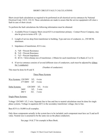
Chap4-30-4521/06/0210:00Page 404.5.2 Voltage DistributionThe voltage distribution in any branch of a network isdetermined from the sequence voltage distribution. Asshown by Equations 4.4, 4.5 and 4.6 and the gradientdiagrams, Figures 4.6(b) and 4.7(b), the positivesequence voltage is a minimum at the fault, whereas thezero and negative sequence voltages are a maximum.Thus, the sequence voltages in any part of the systemmay be given generally as:Power systemABOFaultLoad(a) Single line diagramj7.5Ωj0.9Ω1.00.755 V1' V I1 Z1 0.08j0.4ΩA n V 2 ' I 2 Z1 C1 n Z1 n 1 n V0 ' I 0 Z 0 C 0 n Z 0 n Equation 4.391Bj2.6Ω 0 j1.6Ω0.1650.1120.192j4.8Ω0.053(b) Zero sequence networkj2.5Ωj1.6Ω1.00.4220.183j0.4ΩBj0.75Ω 0 j0.45Ω0.3950.3730.556j18.85ΩUsing the above equation, the fault voltages at bus B inthe previous example can be found.From the positive sequence distribution diagram Figure4.8(c):(c) Positive and negative sequence networks[Fa u l t C a l c u l a t i o n s{V '1 V I1 Z1 j (0.395 0.75 ) (0.373 0.45 )Figure 4.14: Typical power system4 1A0.022 n C1 n Z1 n —Assuming that V 63.5 volts, then:[V ' 2 V I1 Z1 j 0.46463.5I 0 13 I a 31.2 A3 x 0.68—If V is taken as the reference vector, then:—I ’a 26.8 -90 A—I ’b I ’c 8.15 -90 A}]From the zero sequence distribution diagram Figure4.8(b):[{V ' 0 I 0 Z 0 j (0.165 2.6 ) (0.112 1.6 )[]}] I 0 Z 0 j 0.608— — —For earth faults, at the fault I1 I2 I0 j31.2A, when— V 63.5 volts and is taken as the reference vector.——Further, Z1 Z0 j0.68 ohms.The vector diagram for the above fault condition isshown in Figure 4.15.Figure 4.15V 'c 61.5-116.4 Hence:—V’1 63.5 - (0.216 x 31.2) 56.76 0 volts—V’2 6.74 180 volts—V’0 2.25 180 voltsI 'b I 'c 8.15-90 V 63.5-0 and, using Equations 4.1:————V a V1 V2 V0V 'a 47.8-0 56.76 -(6.74 2.25)—V’a 47.8 0 ————V’b a2 V’1 aV’2 V’0I 'a 26.8-90 V 'b 61.5-116.4 56.76a2 -(6.74a 2.25)—V’b 61.5 -116.4 voltsFigure 4.15: Vector diagram: Fault currentsand voltages in branch OB due to P-E fault at bus A 40 Network Protection & Automation Guide
Chap4-30-4521/06/0210:00Page 41————V’c aV’1 a2V’2 V’0——— —and since Vbn a2 Van , Vcn aVan then:——VR 3Vne Equation 4.43—where Vcn - neutral displacement voltage. 56.75a -(6.74a2 2.25)—V’c 61.5 116.4 voltsThese voltages are shown on the vector diagram, Figure4.15.4.6 EFFECT OF SYSTEM EARTHINGON ZERO SEQUENCE QUANTITIESMeasurements of residual quantities are made usingcurrent and voltage transformer connections as shown inFigure 4.16. If relays are connected into the circuits inplace of the ammeter and voltmeter, it follows that earthfaults in the system can be detected.It has been shown previously that zero sequence currentsflow in the earth path during earth faults, and it followsthat the nature of these currents will be influenced bythe method of earthing. Because these quantities areunique in their association with earth faults they can beutilised in protection, provided their measurement andcharacter are understood for all practical systemconditions.IaAIbBIcCVaeVbeVceA4.6.1 Residual Current and VoltageResidual currents and voltages depend for their existenceon two factors:V(a) Residual currenta. a system connection to earth at two or more pointsb. a potential difference between the earthed pointsresulting in a current flow in the earth pathsHence: V ce I R Ia Ib IcandV R V ae V beAlso, from Equations 4.2:I R 3 I 0 V R 3 V0 It should be further noted that:V ae V an V ne V be V bn V ne V ce V cn V ne Equation 4.40 Equation 4.41Figure 4.16: Measurement of residual quantities— —4.6.2 System Z0 / Z1 Ratio— —The system Z0 / Z1 ratio is defined as the ratio of zerosequence and positive sequence impedances viewed fromthe fault; it is a variable ratio, dependent upon themethod of earthing, fault position and system operatingarrangement.When assessing the distribution of residual quantitiesthrough a system, it is convenient to use the fault pointas the reference as it is the point of injection ofunbalanced quantities into the system. The residualvoltage is measured in relation to the normal phaseneutral system voltage and the residual current iscompared with the three-phase fault current at the faultpoint. It can be shown [4.4/4.5] that the character ofthese quantities can be expressed in terms of the system— —Z0 / Z1 ratio.The positive sequence impedance of
standards dealing with fault level calculations. For an example of practical three-phase fault calculations, consider a fault at Ain Figure 3.9. With the network reduced as shown in Figure 4.2, the load voltage at A before the fault occurs is: Figure 4.2: — V 0.97 — E' -1.55 — I For practical working conditions, — E' 〉〉〉1.55 —