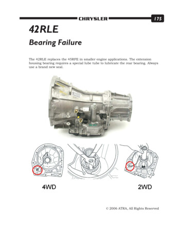
Transcription
TJAUTOMATIC TRANSMISSION - 42RLE21 - 37AUTOMATIC TRANSMISSION - 42RLETABLE OF CONTENTSpagepageAUTOMATIC TRANSMISSION - 42RLEDESCRIPTION . . . . . . . . . . . . . . . . . . . . . . . . . 38OPERATION . . . . . . . . . . . . . . . . . . . . . . . . . . . 40DIAGNOSIS AND TESTINGDIAGNOSIS AND TESTING - AUTOMATICTRANSMISSION . . . . . . . . . . . . . . . . . . . . . . 46DIAGNOSIS AND TESTING - ROAD TEST . . . 46DIAGNOSIS AND TESTING - HYDRAULICPRESSURE TESTS . . . . . . . . . . . . . . . . . . . . 47DIAGNOSIS AND TESTING - CLUTCH AIRPRESSURE TESTS . . . . . . . . . . . . . . . . . . . . 50DIAGNOSIS AND TESTING - FLUIDLEAKAGE . . . . . . . . . . . . . . . . . . . . . . . . . . . 50STANDARD PROCEDURE - ALUMINUMTHREAD REPAIR . . . . . . . . . . . . . . . . . . . . . . 51REMOVAL . . . . . . . . . . . . . . . . . . . . . . . . . . . . . 51DISASSEMBLY . . . . . . . . . . . . . . . . . . . . . . . . . 53ASSEMBLY . . . . . . . . . . . . . . . . . . . . . . . . . . . . 69INSTALLATION . . . . . . . . . . . . . . . . . . . . . . . . . 85SCHEMATICS AND DIAGRAMS - 42RLETRANSMISSION. . . . . . . . . . . . . . . . . . . . . . 88SPECIFICATIONS42RLE AUTOMATIC TRANSMISSION . . . . . . 101SPECIAL TOOLS42RLE AUTOMATIC TRANSMISSION . . . . . . 103ACCUMULATORDESCRIPTION . . . . . . . . . . . . . . . . . . . . . . . . 106OPERATION . . . . . . . . . . . . . . . . . . . . . . . . . . 106ADAPTER HOUSING SEALREMOVAL . . . . . . . . . . . . . . . . . . . . . . . . . . . . 106INSTALLATION . . . . . . . . . . . . . . . . . . . . . . . . 106BEARINGSADJUSTMENTSBEARING ADJUSTMENT PROCEDURES . . . 106BRAKE TRANSMISSION SHIFT INTERLOCKMECHANISMDESCRIPTION . . . . . . . . . . . . . . . . . . . . . . . . 107OPERATION . . . . . . . . . . . . . . . . . . . . . . . . . . 108REMOVAL . . . . . . . . . . . . . . . . . . . . . . . . . . . . 108INSTALLATION . . . . . . . . . . . . . . . . . . . . . . . . 108ADJUSTMENTSADJUSTMENT - BRAKE TRANSMISSIONSHIFT INTERLOCK CABLE . . . . . . . . . . . . . 108DRIVING CLUTCHESDESCRIPTION . . . . . . . . . . . . . . . . . . . . . . . . 109OPERATION . . . . . . . . . . . . . . . . . . . . . . . . . . 109FLUID AND FILTERDIAGNOSIS AND TESTINGDIAGNOSIS AND TESTING - CAUSES OFBURNT FLUID . . . . . . . . . . . . . . . . . . . . . . . 110EFFECTS OF INCORRECT FLUID LEVEL . . 110FLUID CONTAMINATION . . . . . . . . . . . . . . . 110STANDARD PROCEDURESTANDARD PROCEDURE - FLUID LEVELCHECK . . . . . . . . . . . . . . . . . . . . . . . . . . . . . 111STANDARD PROCEDURE - FLUID/FILTERSERVICE . . . . . . . . . . . . . . . . . . . . . . . . . . . 111STANDARD PROCEDURE - TRANSMISSIONFILL . . . . . . . . . . . . . . . . . . . . . . . . . . . . . . . 112GEARSHIFT CABLEREMOVAL . . . . . . . . . . . . . . . . . . . . . . . . . . . . 113INSTALLATION . . . . . . . . . . . . . . . . . . . . . . . . 113HOLDING CLUTCHESDESCRIPTION. . . . . . . . . . . . . . . . . . . . . . . . 114OPERATION . . . . . . . . . . . . . . . . . . . . . . . . . . 114INPUT CLUTCH ASSEMBLYDISASSEMBLY . . . . . . . . . . . . . . . . . . . . . . . . 114ASSEMBLY . . . . . . . . . . . . . . . . . . . . . . . . . . . 121INPUT SPEED SENSORDESCRIPTION . . . . . . . . . . . . . . . . . . . . . . . . 131OPERATION . . . . . . . . . . . . . . . . . . . . . . . . . . 131REMOVAL . . . . . . . . . . . . . . . . . . . . . . . . . . . . 131INSTALLATION . . . . . . . . . . . . . . . . . . . . . . . . 132OIL PUMPDESCRIPTION . . . . . . . . . . . . . . . . . . . . . . . . 132OPERATION . . . . . . . . . . . . . . . . . . . . . . . . . . 132DISASSEMBLY . . . . . . . . . . . . . . . . . . . . . . . . 132ASSEMBLY . . . . . . . . . . . . . . . . . . . . . . . . . . . 133OUTPUT SPEED SENSORDESCRIPTION . . . . . . . . . . . . . . . . . . . . . . . . 134OPERATION . . . . . . . . . . . . . . . . . . . . . . . . . . 134REMOVAL . . . . . . . . . . . . . . . . . . . . . . . . . . . . 134INSTALLATION . . . . . . . . . . . . . . . . . . . . . . . . 134OVERDRIVE SWITCHDESCRIPTION . . . . . . . . . . . . . . . . . . . . . . . . 135OPERATION . . . . . . . . . . . . . . . . . . . . . . . . . . 135REMOVAL . . . . . . . . . . . . . . . . . . . . . . . . . . . . 135INSTALLATION . . . . . . . . . . . . . . . . . . . . . . . . 135PLANETARY GEARTRAINDESCRIPTION . . . . . . . . . . . . . . . . . . . . . . . . 136OPERATION . . . . . . . . . . . . . . . . . . . . . . . . . . 136OIL PUMP SEALREMOVAL . . . . . . . . . . . . . . . . . . . . . . . . . . . . 136INSTALLATION . . . . . . . . . . . . . . . . . . . . . . . . 136
21 - 38TJAUTOMATIC TRANSMISSION - 42RLESHIFT MECHANISMDESCRIPTION . . . . . . . . . . . . . . . . .OPERATION . . . . . . . . . . . . . . . . . . .DIAGNOSIS AND TESTING - SHIFTMECHANISM . . . . . . . . . . . . . . . . .ADJUSTMENTS - SHIFT MECHANISMSOLENOIDDESCRIPTION . . . . . . . . . . . . . . . . .OPERATION . . . . . . . . . . . . . . . . . . .SOLENOID/PRESSURE SWITCH ASSYDESCRIPTION . . . . . . . . . . . . . . . . .OPERATION . . . . . . . . . . . . . . . . . . .REMOVAL . . . . . . . . . . . . . . . . . . . . .INSTALLATION . . . . . . . . . . . . . . . . .TORQUE CONVERTERDESCRIPTION . . . . . . . . . . . . . . . . .OPERATION . . . . . . . . . . . . . . . . . . .REMOVAL . . . . . . . . . . . . . . . . . . . . .INSTALLATION . . . . . . . . . . . . . . . . . . . . . . . 136. . . . . . . 136. . . . . . . 136. . . . . . 137. . . . . . . 137. . . . . . . 138. 138. 139. 139. 140. 141. 145. 146. 146AUTOMATIC TRANSMISSION 42RLEDESCRIPTIONThe 42RLE (Fig. 1) is a four-speed transmissionthat is a conventional hydraulic/mechanical assemblycontrolled with adaptive electronic controls and monitors. The hydraulic system of the transmission consists of the transmission fluid, fluid passages,hydraulic valves, and various line pressure controlcomponents. An input clutch assembly which housesthe underdrive, overdrive, and reverse clutches isused. It also utilizes separate holding clutches: 2nd/4th gear and Low/Reverse. The primary mechanicalcomponents of the transmission consist of the following: Three multiple disc input clutches Two multiple disc holding clutches Four hydraulic accumulators Two planetary gear sets Hydraulic oil pump Valve body Solenoid/Pressure switch assemblyTRANSMISSION CONTROL RELAYDESCRIPTION . . . . . . . . . . . . . . . . . . .OPERATION . . . . . . . . . . . . . . . . . . . . .TRANSMISSION RANGE SENSORDESCRIPTION . . . . . . . . . . . . . . . . . . .OPERATION . . . . . . . . . . . . . . . . . . . . .REMOVAL . . . . . . . . . . . . . . . . . . . . . . .INSTALLATION . . . . . . . . . . . . . . . . . . .TRANSMISSION TEMPERATURE SENSORDESCRIPTION . . . . . . . . . . . . . . . . . . .OPERATION . . . . . . . . . . . . . . . . . . . . .VALVE BODYDESCRIPTION . . . . . . . . . . . . . . . . . . .OPERATION . . . . . . . . . . . . . . . . . . . . .REMOVAL . . . . . . . . . . . . . . . . . . . . . . .DISASSEMBLY . . . . . . . . . . . . . . . . . . .ASSEMBLY . . . . . . . . . . . . . . . . . . . . . .INSTALLATION . . . . . . . . . . . . . . . . . . . . . . . 146. . . . . 147. 147. 147. 148. 148. . . . . 149. . . . . 149. 149. 150. 153. 154. 159. 164Control of the transmission is accomplished byfully adaptive electronics. Optimum shift schedulingis accomplished through continuous real-time sensorfeedback information provided to the TransmissionControl Module (TCM) portion of the PowertrainControl Module (PCM).The TCM is the heart of the electronic control system and relies on information from various directand indirect inputs (sensors, switches, etc.) to determine driver demand and vehicle operating conditions. With this information, the TCM can calculateand perform timely and quality shifts through various output or control devices (solenoid pack, transmission control relay, etc.).The TCM also performs certain self-diagnosticfunctions and provides comprehensive information(sensor data, DTC’s, etc.) which is helpful in properdiagnosis and repair. This information can be viewedwith the DRBt scan tool.
AUTOMATIC TRANSMISSION - 42RLEAUTOMATIC TRANSMISSION - 42RLE (Continued)21 - 39Fig. 1 42RLE Automatic TransmissionTJ
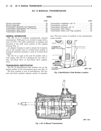
21 - 40TJAUTOMATIC TRANSMISSION - 42RLEAUTOMATIC TRANSMISSION - 42RLE (Continued)12345-DRIVEPLATETORQUE CONVERTERINPUT SHAFTUNDERDRIVE CLUTCHOVERDRIVE CLUTCH6 - REVERSE CLUTCH7 - FRONT PLANET CARRIER8 - REAR PLANET CARRIER9 - OUTPUT SHAFT10 - SNAP RINGTRANSMISSION IDENTIFICATIONFig. 2 Identification Label Breakdown1 - T TRACEABILITY2 - SUPPLIER CODE (PK KOKOMO)3 - COMPONENT CODE (TK KOKOMO TRANSMISSION)4 - BUILD DAY (350 DEC. 15)5 - BUILD YEAR (1 2001)6 - ASSEMBLY LINE CODE7 - BUILD SEQUENCE NUMBER8 - LAST THREE OF P/N9 - CHANGE LEVEL10 - TRANSMISSION PART NUMBER11 - P PART NUMBERThe 42RLE transmission can be identified by abarcode label that is affixed to the upper left area ofthe bellhousing.The label contains a series of digits that can betranslated into useful information such as transmission part number (10), date of manufacture (4, 5),manufacturing origin (2), assembly line identifier (6),build sequence number (7), etc. (Fig. 2).If the tag is not legible or is missing, the “PK”number, which is stamped into the left rear flange ofthe transmission case, can be referred to for identification. The entire part number, build code, andsequence number are stamped into the flange.11 - STUB SHAFT12 - LOW/REVERSE CLUTCH13 - 2/4 CLUTCH14 - OIL PUMPOPERATIONThe 42RLE transmission ratios are:First2.84 : 1Second1.57 : 1Third1.00 : 1Overdrive0.69 : 1Reverse2.21 : 1
TJAUTOMATIC TRANSMISSION - 42RLEAUTOMATIC TRANSMISSION - 42RLE (Continued)21 - 41FIRST GEAR POWERFLOWIn first gear range, torque input is through theunderdrive clutch (1) (Fig. 3) to the underdrive hubassembly. The underdrive hub is splined to the rearsun gear. When the underdrive clutch is applied, itrotates the underdrive hub and rear sun gear. TheL/R clutch (2) is applied to hold the front carrier/rearannulus assembly. The rear sun gear drives the rearplanetary pinion gears. The rear planetary piniongears are forced to walk around the inside of the stationary rear annulus gear. The pinions are pinned tothe rear carrier and cause the rear carrier assemblyto rotate as they walk around the annulus gear. Thisprovides the torque output for first gear. The otherplanetary gearset components are freewheeling. Thefirst gear ratio is 2.84:1.Fig. 3 First Gear Powerflow1 - UNDERDRIVE CLUTCH APPLIED (Turns Rear Sun)2 - LOW-REVERSE CLUTCH APPLIED (Holds Rear Annulus/FrontCarrier)
21 - 42AUTOMATIC TRANSMISSION - 42RLEAUTOMATIC TRANSMISSION - 42RLE (Continued)SECOND GEAR POWERFLOWSecond gear is achieved by having both planetarygear sets (Fig. 4) contribute to torque multiplication.As in first gear, torque input is through the underdrive clutch (1) to the rear sun gear. The 2/4 clutch(2) is applied to hold the front sun gear stationary.The rotating rear sun gear turns the rear planetarypinions. The rear pinions rotate the rear annulus/front carrier assembly. The pinions of the front carrier walk around the stationary front sun gear. Thistransmits torque to the front annulus/rear carrierassembly, which provides output torque and a gearratio of 1.57:1.Fig. 4 Second Gear Powerflow1 - UNDERDRIVE CLUTCH APPLIED (Turns Rear Sun)2 - 2-4 CLUTCH APPLIED (Holds Front Sun)TJ
TJAUTOMATIC TRANSMISSION - 42RLEAUTOMATIC TRANSMISSION - 42RLE (Continued)21 - 43THIRD GEAR POWERFLOWIn third gear, two input clutches are applied to provide torque input: the underdrive clutch (1) (Fig. 5)and overdrive clutch (2). The underdrive clutchrotates the rear sun gear, while the overdrive clutchrotates the front carrier/rear annulus assembly. Theresult is two components (rear sun gear and rearannulus gear) rotating at the same speed and in thesame direction. This effectively locks the entire planetary gearset together and is rotated as one unit. Thegear ratio in third is 1:1.Fig. 5 Third Gear Powerflow1 - UNDERDRIVE CLUTCH APPLIED (Turns Rear Sun)2 - OVERDRIVE CLUTCH APPLIED (Turns Front Carrier/RearAnnulus)
21 - 44AUTOMATIC TRANSMISSION - 42RLEAUTOMATIC TRANSMISSION - 42RLE (Continued)FOURTH GEAR POWERFLOWIn fourth gear input torque is through the overdrive clutch (1) (Fig. 6) which drives the front carrier.The 2/4 clutch (2) is applied to hold the front sungear. As the overdrive clutch rotates the front carrier,it causes the pinions of the front carrier to walkaround the stationary front sun gear. This causes thefront carrier pinions to turn the front annulus/rearcarrier assembly which provides output torque. Infourth gear, transmission output speed is more thanengine input speed. This situation is called overdriveand the gear ratio is 0.69:1.Fig. 6 Fourth Gear Powerflow1 - OVERDRIVE CLUTCH APPLIED (Turns Rear Sun)2 - 2-4 CLUTCH APPLIED (Holds Front Sun)TJ
TJAUTOMATIC TRANSMISSION - 42RLEAUTOMATIC TRANSMISSION - 42RLE (Continued)REVERSE GEAR POWERFLOWIn reverse, input (Fig. 7) power is through thereverse clutch (1). When applied, the reverse clutchdrives the front sun gear through the overdrive huband shaft. The L/R clutch (2) is applied to hold thefront carrier/rear annulus assembly stationary. Thefront carrier is being held by the L/R clutch so thepinions are forced to rotate the front annulus/rearcarrier assembly in the reverse direction. Outputtorque is provided, in reverse, with a gear ratio of2.21:1.Fig. 7 Reverse Gear Powerflow1 - LOW-REVERSE CLUTCH APPLIED (Holds Rear Annulus FrontCarrier)2 - REVERSE CLUTCH APPLIED (Turns Front Sun)21 - 45
21 - 46AUTOMATIC TRANSMISSION - 42RLEAUTOMATIC TRANSMISSION - 42RLE (Continued)DIAGNOSIS AND TESTINGDIAGNOSIS AND TESTING - AUTOMATICTRANSMISSIONCAUTION: Before attempting any repair on the42RLE Four Speed Automatic Transmission, alwayscheck for proper shift cable adjustment. Also checkfor diagnostic trouble codes with the DRBT scantool and the 42RLE Transmission Diagnostic Procedure Manual.42RLE automatic transmission malfunctions maybe caused by these general conditions: Poor engine performance Improper adjustments Hydraulic malfunctions Mechanical malfunctions Electronic malfunctionsWhen diagnosing a problem always begin withrecording the complaint. The complaint should bedefined as specific as possible. Include the followingchecks: Temperature at occurrence (cold, hot, both) Dynamic conditions (acceleration, deceleration,upshift, cornering) Elements in use when condition occurs (whatgear is transmission in during condition) Road and weather conditions Any other useful diagnostic information.After noting all conditions, check the easily accessible variables:TJFluid level and conditionShift cable adjustmentDiagnostic trouble code inspectionThen perform a road test to determine if the problem has been corrected or that more diagnosis is necessary. If the problem exists after the preliminarytests and corrections are completed, hydraulic pressure checks should be performed. DIAGNOSIS AND TESTING - ROAD TESTPrior to performing a road test, verify that thefluid level, fluid condition, and linkage adjustmenthave been approved.During the road test, the transmission should beoperated in each position to check for slipping andany variation in shifting.If the vehicle operates properly at highway speeds,but has poor acceleration, the converter stator overrunning clutch may be slipping. If acceleration is normal, but high throttle opening is needed to maintainhighway speeds, the converter stator clutch mayhave seized. Both of these stator defects requirereplacement of the torque converter and thoroughtransmission cleaning.Slipping clutches can be isolated by comparing the“Elements in Use” chart with clutch operationencountered on a road test. This chart identifieswhich clutches are applied at each position of theselector lever.A slipping clutch may also set a DTC and can bedetermined by operating the transmission in allselector positions.
TJAUTOMATIC TRANSMISSION - 42RLE21 - 47AUTOMATIC TRANSMISSION - 42RLE (Continued)ELEMENTS IN USE AT EACH POSITION OF SELECTOR LEVERShift LeverPositionINPUT CLUTCHESUnderdriveHOLDING CLUTCHESOverdriveReverse2/4P - PARKLow/ReverseXR - REVERSEXXN - NEUTRALXOD OVERDRIVEFirstXSecondXDirectXOverdriveXXXXXD - DRIVE*FirstXSecondXDirectXXXXL - LOW*FirstXSecondXDirectXXXX* Vehicle upshift and downshift speeds are increased when in these selector positions.The process of elimination can be used to detectany unit which slips and to confirm proper operationof good units. Road test analysis can diagnose slipping units, but the cause of the malfunction cannotbe determined. Practically any condition can becaused by leaking hydraulic circuits or stickingvalves.DIAGNOSIS AND TESTING - HYDRAULICPRESSURE TESTSPressure testing is a very important step in thediagnostic procedure. These tests usually reveal thecause of most transmission problems.Before performing pressure tests, be certain thatfluid level and condition, and shift cable adjustmentshave been checked and approved. Fluid must be atoperating temperature (150 to 200 degrees F.).Install an engine tachometer, raise vehicle on hoistwhich allows the wheels to turn, and positiontachometer so it can be read.Using special adapters L-4559, attach 300 psigauge(s) C-3293SP to the port(s) required for testbeing conducted.Test port locations are shown in the Pressure Tapsgraphic. (Fig. 8)Fig. 8 Pressure Taps1234567-TORQUE CONVERTER CLUTCH OFFREVERSELOW/REVERSE2/4UNDERDRIVETORQUE CONVERTER CLUTCH ONOVERDRIVE
AUTOMATIC TRANSMISSION - 42RLETJTEST ONE - SELECTOR IN MANUAL 1 (1st Gear)(4) Overdrive clutch pressure should read 74 to 95psi.(5) Move selector lever to the DRIVE position andincrease indicated vehicle speed to 30 mph.(6) The vehicle should be in second gear and overdrive clutch pressure should be less than 5 psi.21 - 48AUTOMATIC TRANSMISSION - 42RLE (Continued)NOTE: This test checks pump output, pressure regulation and condition of the low/reverse clutchhydraulic circuit and shift schedule.(1) Attach pressure gauge to the low/reverse clutchtap.(2) Move selector lever to the MANUAL 1 position.(3) Allow vehicle wheels to turn and increasethrottle opening to achieve an indicated vehicle speedto 20 mph.(4) Low/reverse clutch pressure should read 115 to145 psi.TEST TWO - SELECTOR IN MANUAL 2 (SecondGear)NOTE: This test checks the underdrive clutchhydraulic circuit as well as the shift schedule.(1) Attach gauge to the underdrive clutch tap.(2) Move selector lever to the MANUAL 2 position.(3) Allow vehicle wheels to turn and increasethrottle opening to achieve an indicated vehicle speedof 30 mph.(4) In second gear the underdrive clutch pressureshould read 110 to 145 psi.TEST TWO A - SELECTOR IN DRIVE (OD ON Fourth Gear)NOTE: This test checks the underdrive clutchhydraulic circuit as well as the shift schedule.(1) Attach gauge to the underdrive clutch tap.(2) Move selector lever to the DRIVE position.Verfy that the OD switch is ON.(3) Allow wheels to rotate freely and increasethrottle opening to achieve an indicated speed of 40mph.(4) Underdrive clutch pressure should read below5 psi. If not, than either the solenoid assembly orcontroller is at fault.TEST THREE - SELECTOR IN DRIVE (OD OFF Third and Second Gear)NOTE: This test checks the overdrive clutchhydraulic circuit as well as the shift schedule.(1) Attach gauge to the overdrive clutch tap.(2) Move selector lever to the DRIVE position.(3) Allow vehicle wheels to turn and increasethrottle opening to achieve an indicated vehicle speedof 20 mph.TEST FOUR - SELECTOR IN DRIVE (OD ON Fourth Gear)NOTE: This test checks the 2/4 clutch hydraulic circuit.(1) Attach gauge to the 2/4 clutch tap.(2) Move selector lever to the DRIVE position.(3) Allow vehicle front wheels to turn and increasethrottle opening to achieve an indicated vehicle speedof 30 mph. Vehicle should be in fourth gear.(4) The 2/4 clutch pressure should read 75 to 95psi.TEST FIVE-SELECTOR IN DRIVE (OD ON - FourthGear, CC on)NOTE: These tests check the torque converterclutch hydraulic circuit.(1) Attach gauge to the torque converter clutch offpressure tap.(2) Move selector lever to the DRIVE position.(3) Allow vehicle wheels to turn and increasethrottle opening to achieve an indicated vehicle speedof 50 mph. Vehicle should be in 4th gear, CC on.CAUTION: Both wheels must turn at the samespeed.(4) Torque converter clutch off pressure should beless than 5 psi.(5) Now attach the gauge to the torque converterclutch on pressure tap.(6) Move selector to the OD position.(7) Allow vehicle wheels to turn and increasethrottle opening to achieve an indicated vehicle speedof 50 mph.(8) Verify the torque converter clutch is appliedmode using the RPM display of the DRB scan tool.(9) Torque converter clutch on pressure should be60-90 psi.TEST SIX-SELECTOR IN REVERSENOTE: This test checks the reverse clutch hydrauliccircuit.(1) Attach gauge to the reverse and low/reverseclutch tap.
TJAUTOMATIC TRANSMISSION - 42RLEAUTOMATIC TRANSMISSION - 42RLE (Continued)(2) Move selector lever to the REVERSE position.(3) Read reverse clutch pressure with output stationary (foot on brake) and throttle opened to achieve1500 rpm.(4) Reverse and low/reverse clutch pressure shouldread 165 to 235 psi.TEST RESULT INDICATIONS(1) If proper line pressure is found in any one test,the pump and pressure regulator are working properly.(2) Low pressure in all positions indicates a defective pump, a clogged filter, or a stuck pressure regulator valve.21 - 49(3) Clutch circuit leaks are indicated if pressuresdo not fall within the specified pressure range.(4) If the overdrive clutch pressure is greater than5 psi in Step 6 of Test Three, a worn reaction shaftseal ring or a defective solenoid assembly is indicated.(5) If the underdrive clutch pressure is greaterthan 5 psi in Step 4 of Test Two-A, a defective solenoid/pressure switch assembly or controller is thecause.ALL PRESSURE SPECIFICATIONS ARE PSI (ON HOIST, WITH WHEELS FREE TO TURN)Gear SelectorPositionActual GearPRESSURE utchLow/ReverseClutchPARK - 0 mph *PARK0-20-50-260-11045-1000-2115-145REVERSE - 0 mph *REVERSE0-20-7165-23550-10035-850-2165-235NEUTRAL - 0 mph *NEUTRAL0-20-50-260-11045-1000-2115-145Low - 20 mph #FIRST110-1450-50-260-11045-1000-2115-145Third - 30 mph #SECOND110-1450-50-260-11045-1001151450-2Third - 45 mph #DIRECT75-9575-950-260-9045-800-20-2OD - 30 mph #OVERDRIVE0-275-950-260-9045-8075-950-2OD - 50 mph #OVERDRIVEWITH TCC0-275-950-20-560-9575-950-2* Engine Speed at 1500 rpm# CAUTION: Both wheels must be turning at same speed.
21 - 50TJAUTOMATIC TRANSMISSION - 42RLEAUTOMATIC TRANSMISSION - 42RLE (Continued)DIAGNOSIS AND TESTING - CLUTCH AIRPRESSURE TESTSREVERSE CLUTCHApply air pressure to the reverse clutch apply passage and watch for the push/pull piston to move rearward. The piston should return to its startingposition when the air pressure is removed.LOW/REVERSE CLUTCHApply air pressure to the low/reverse clutch feedhole passage. Look in the area where the low/reversepiston contacts the first separator plate. Watch carefully for the piston to move forward. The pistonshould return to its original position after the airpressure is removed.UNDERDRIVE CLUTCHFig. 9 Air Pressure Test Plate1 - AIR PRESSURE TEST PLATES2 - 2/4 CLUTCH RETAINER HOLEInoperative clutches can be located by substitutingair pressure for fluid pressure. The clutches may betested by applying air pressure to their respectivepassages after the valve body has been removed. UseSpecial Tool 6599-1 (1) and 6599-2 (1) to perform test(Fig. 9).To make air pressure tests, proceed as follows:NOTE: The compressed air supply must be free ofall dirt and moisture. Use a pressure of 30 psi.(1) Remove oil pan and valve body. (Refer to 21 TRANSMISSION/AUTOMATIC - 42RLE/VALVEBODY - REMOVAL)(2) Apply air pressure to the holes in the specialtool (1), one at a time.(3) Listen for the clutch to apply. It will give aslight thud sound. If a large amount of air is heardescaping, the transmission must be removed fromvehicle, disassembled and all seals inspected.2/4 CLUTCHApply air pressure to the feed hole located on the2/4 clutch retainer (2). Look in the area where the2/4 piston contacts the first separator plate andwatch carefully for the 2/4 piston to move rearward.The piston should return to its original position afterthe air pressure is removed.OVERDRIVE CLUTCHApply air pressure to the overdrive clutch applypassage and watch for the push/pull piston to moveforward. The piston should return to its startingposition when the air pressure is removed.Fig. 10 Testing Underdrive Clutch1 - AIR PRESSURE TEST PLATE 6599-12 - AIR NOZZLEBecause this clutch piston cannot be seen, its operation is checked by function. Air pressure is appliedto the low/reverse or the 2/4 clutches. This locks theoutput shaft. Use a piece of rubber hose wrappedaround the input shaft and a pair of clamp-on pliersto turn the input shaft. Next apply air pressure (Fig.10) to the underdrive clutch. The input shaft shouldnot rotate with hand torque. Release the air pressureand confirm that the input shaft will rotate.DIAGNOSIS AND TESTING - FLUID LEAKAGEFLUID LEAKAGE - TORQUE CONVERTER HOUSINGAREAWhen diagnosing converter housing fluid leaks,three actions must be taken before repair:(1) Verify proper transmission fluid level.(2) Verify that the leak originates from the converter housing area and is transmission fluid.(3) Determine the true source of the leak.
TJAUTOMATIC TRANSMISSION - 42RLEAUTOMATIC TRANSMISSION - 42RLE (Continued)21 - 51Fig. 12 Converter Leak Points - TypicalFig. 11 Converter Housing Leak Paths1234567-PUMP SEALPUMP VENTPUMP BOLTPUMP GASKETCONVERTER HOUSINGCONVERTERREAR MAIN SEAL LEAKFluid leakage at or around the torque converterarea (Fig. 11) may originate from an engine oil leak.The area should be examined closely. Factory fillfluid is red and, therefore, can be distinguished fromengine oil.Some suspected converter housing fluid leaks maynot be leaks at all. They may only be the result ofresidual fluid in the converter housing, or excessfluid spilled during factory fill, or fill after repair.Converter housing leaks have several potentialsources. Through careful observation, a leak sourcecan be identified before removing the transmissionfor repair.Pump seal leaks tend to move along the drive hub(Fig. 11) and onto the rear of the converter. Pumpo-ring or pump body leaks follow the same path as aseal leak. Pump attaching bolt leaks are generallydeposited on the inside of the converter housing andnot on the converter itself. Pump seal or gasket leaks(Fig. 11)usually travel down the inside of the converter housing.TORQUE CONVERTER LEAKAGEPossible sources of torque converter leakage are: Torque converter weld leaks at the outside diameter weld. (Fig. 12) Torque converter hub weld. (Fig. 12)STANDARD PROCEDURE - ALUMINUMTHREAD REPAIRDamaged or worn threads in the aluminum transmission case and valve body can be repaired by the1234-OUTSIDE DIAMETER WELDTORQUE CONVERTER HUB WELDSTARTER RING GEARLUGuse of Heli-Coilst, or equivalent. This repair consistsof drilling out the worn-out damaged threads. Thentap the hole with a special Heli-Coilt tap, or equivalent, and installing a Heli-Coilt insert, or equivalent,into the hole. This brings the hole back to its originalthread size.Heli-Coilt, or equivalent, tools, and inserts arereadily available from most automotive parts suppliers.REMOVAL(1) Disconnect battery negative cable.(2) Raise and support vehicle.(3) Disconnect and lower or remove necessaryexhaust components.(4) Remove engine-to-transmission bending bracesor engine collar.(5) Remove starter motor. (Refer to 8 - ELECTRICAL/STARTING/STARTER MOTOR - REMOVAL)(6) On 4.0L engine equipped vehicles, disconnectand remove crankshaft position sensor (Fig. 13).Retain sensor attaching bolt.CAUTION: The crankshaft position sensor can bedamaged during transmission removal (or installation) if the sensor is left in place. To avoid damage,remove the sensor before removing the transmission.(7) If transmission is being removed for overhaul,remove transmission oil pan, drain fluid and reinstallpan. (Refer to 21 - TRANSMISSION/AUTOMATIC 42RLE/FLUID - STANDARD PROCEDURE)(8) Remove torque converter access cover.(9) Rotate crankshaft in clockwise direction untilconverter bolts are accessible. Then remove bolts oneat a time. Rotate crankshaft with socket wrench ondampener bolt.
21 - 52AUTOMATIC TRANSMISSION - 42RLEAUTOMATIC TRANSMISSION - 42RLE (Continued)TJ(12) Disconnect wires from the transmission rangesensor (Fig. 14) and the solenoid/pressure switchassembly (Fig. 15).Fig. 15 Solenoid/Pressure Switch Assembly1 - SOLENOID/PRESSURE SWITCH ASSEMBLY CONNECTORFig. 13 Crankshaft Position Sensor1234-CRANKSHAFT POSITION SENSORMOUNTING BOLTELECTRICAL CONNECTORTRANSMISSION BELLHOUSING(10) Mark propeller shaft and axle yokes forassembly alignment. Then disconnect and removepropeller shafts. (Refer to 3 - DIFFERENTIAL &DRIVELINE/PROPELLERSHAFT/PROPELLERSHAFT - REMOVAL)(11) Disconnect wires from the input and outputspeed sensors (Fig. 14).(13) Disconnect gearshift cable from transmissionmanual valve lever.(14) Disconnect shift rod from transfer case shiftlever or remove shift lever from transfer case.(15) Support rear of engine with safety stand or jack.(16) Raise transmission slightly with service jack torelieve load on skid plate and transmission support.(17) Remove bolts securing rear support (Fig. 16)and cushion to transmission and skid plate. Raisetransmission slightly, slide exhaust hanger arm frombracket and remove rear support.(18) Remove bolts attaching skid plate (Fig. 16) toframe and remove skid plate. (Refer to 13 - FRAMEFig. 16 Transmission Mount - Automatic TransmissionFig. 14 Input and Output Speed Sensors andTransmission Range Sensor1 - INPUT SPEED SENSOR2 - OUTPUT SPEED SENSOR3 - TRANSMISSI
AUTOMATIC TRANSMISSION - 42RLE DESCRIPTION The 42RLE (Fig. 1) is a four-speed transmission that is a conventional hydraulic/mechanical assembly controlled with adaptive electronic controls and mon-itors. The hydraulic system of the transmission con-sists of the transmission fluid, fluid passages, hydraulic valves, and various line pressure control