Transcription
Operating, Installation and Servicing Instructions forIndirect oil fired pool & spa heatersModels: COH110, COH180, COH220, COH280WARNING: If the information in these instructions are not followed exactly, a fireor explosion may result causing property damage, personal injury or death.Do not store or use gasoline or other flammable vapours and liquids in the vicinity of thisor any other appliance.THIS APPLIANCE MUST BE INSTALLED: By a competent person. In accordance with the rules in force. in accordance with these operating, installation and servicing instructions. In open air or in a room which is separated from living rooms and provided with appropriate ventilation ventilation directly to the outside.READ THESE INSTRUCTIONS BEFORE INSTALLING AND OPERATING THIS APPLIANCEM3491C
HEALTH AND SAFETYINFORMATION FOR THE INSTALLER AND SERVICE ENGINEER.Under the Consumer Protection Act 1987 and the Health and Safety at Work Act 1974, it is a requirement to provideinformation on substances hazardous to health (COSHH Regulations 1988).The Company takes every reasonable care to ensure that these products are designed and constructed to meet thesegeneral safety requirements, when properly used and installed.To fulfil this requirement products are comprehensively tested and examined before despatch.This appliance may contain some of the materials below.When working on the appliance it is the Users/Engineers responsibility to ensure that any necessary personal protective clothing or equipment is worn appropriate to parts that could be considered as being hazardous to health andsafety.INSULATION & SEALSGlass Rope, Mineral Wool, Insulation Pads, Ceramic Fibre, Fibre Glass Insulation: may be harmful if inhaled, may beirritating to the skin, eyes, nose or throat. When handling avoid inhalation and contact with the skin or eyes. Use(disposable) gloves, face masks and eye protection. After handling wash hands and other exposed parts. When disposing, reduce dust with water spray, ensure parts are securely wrapped.GLUES, SEALANTS & PAINTGlues, Sealants and Paint are used in the product and present no known hazards when used in the manner for whichthey are intended.KEROSENE & GAS OIL FUELS (MINERAL OILS)1. The effect of mineral oils on the skin vary according to the duration of exposure.2. The lighter fractions also remove the protective grease normally present on the surface of the skin rendering theskin dry, liable to crack and more prone to damage caused by cuts and abrasions.3. Skin rashes (oil Acne). Seek immediate medical attention for any rash, wart or sore developing on any part of thebody, particularly the scrotum.4. Avoid as far as possible any skin contact with mineral oil or with clothing contaminated with mineral oil.5. Never breath any mineral oil vapours. Do not fire the Burner in the open i.e. out of the Boiler as a misfire will causeunburnt oil vapours.6. Barrier cream containing 9-04-02lanolin such as Rosalex Antisolv, is highly recommended together with a strict routine ofpersonal cleansing.7. Under no circumstances should mineral oils be taken internally.OFTEC Code of Practice OCP/1: 1995 For the Safe Installation, Commissioning, Maintenance and Fault Rectification ofOil Firing Equipment should be consulted.Due to a policy of continual development the Manufacturer reserves the right to alter or amend the design of itsproducts without prior notice.COH Oil Pool Heater1GB, IE
CONTENTSSECTION 1 - USER INSTRUCTIONSSECTION 5 - 141:155:15:25:35:45:55:6Safety NotesAir SupplyConnectionsInstallation & CommissioningQuick StartSummary of ControlsRe-pressurisingRunning the Pool PumpSwitching off, temporarilySwitching off for the winterOil deliveryMaintenanceTrouble shootingServiceWater QualityConventional FluesAir SupplyBalanced Flue HeatersBalanced Flue TerminalsTerminal GuardsPositioning the HeaterSECTION 6 - BALANCED FLUE INSTALLATION6:16:26:36:4General InformationHorizontal Balanced FluesVertical Balanced FluesOutdoor Flue KitsSECTION 2 - GENERAL INFORMATIONSECTION 7 - :8IntroductionPatentsFlue OptionsCommissioningSafetySECTION 3 - TECHNICAL DATA3:13:23:33:43:53:6Liquid FuelsHeater Technical DetailsBurner DetailsElectricsDimensionsCommissioning DataSECTION 4 - ndards and RegulationsHeater ControlsInstallation WiringIf combined with heatingSiting & PositioningThe HearthOil StorageOil SupplyOil BurnerSensor positionsWiring DiagramsCOH Oil Pool HeaterGeneral InformationFilling the HeaterSetting up the ControlsPressure SwitchResponsibilityReportingCommissioning Check ListCommissioning TestsSECTION 8 - MAINTENANCE8:18:28:3MaintenanceAir Shutter AdjustmentBaffle ArrangementSECTION 9 - SPARES & ACCESSORIES9:19:29:3Spare PartsAccessoriesBurner PartsSECTION 10 - FAULT FINDING10:110:210:3GeneralControl Fault DiagnosisFault Finding Chart2GB, IE
1: USER INSTRUCTIONS1:1 Important Safety NotesTo obtain the best possible performance and trouble freeoperation from your Heater, it is important that you readthese instructions carefully. Your Pool Heater has built-insafety features, which are detailed in the relevant sectionof this manual.Please note: It is essential in the interest of the Heaterefficiency and reliable performance that once the Heaterhas been installed it is first commissioned by an OFTEC.*registered engineer. It is the responsibility of the installerto ensure that the Heater is commissioned.If an engineer is not known, The Manufacturer will bepleased to provide details of an approvedcommissioning and servicing engineer from their list ofapproved engineers.If it is known or suspected that a fault exists on the Heater,it MUST NOT be used until the fault has been corrected bya competent engineer (see Section 1:13, Trouble Shooting - Failure to Start)It is essential that these instructions are strictlyfollowed for safe and economic operation. Failure to observe these instructions may invalidate your right to freebreakdown cover during the guarantee period.As this an oil burner appliance some parts will becomevery hot and so care must be taken.We recommend that you keep these instructions in a placenear your Heater for easy reference.1:2 Air Supply to Heater - Conventional FlueWhere your Heater is used on an open conventional fluesystem, a permanent air supply is required for combustion. Clearances provided for air entry at the rear of theappliance and into the building in which it is installed,must be kept free of obstruction. For further explanationplease refer to section 5:1 and 5:2.1:3 ConnectionsYour Heater should be connected to an electrical supplycomplying with the Electrical Wiring Regulations (BS7671):as well as an oil supply complying with BS541; and anappropriate flue system.ALWAYS SWITCH OFF THE ELECTRICAL SUPPLY beforeremoving any of the covers for cleaning.COH Oil Pool HeaterIf any part of the Heater or its flue is modified then theguarantee will be invalidated.1:4 Installation & CommissioningAfter your Heater has been installed it MUST be commissioned preferably by an OFTEC*. Registered installer,or by one of our recommended service engineers. Commissioning involves testing the Heater to ensure that itis working correctly, and also setting the Burner correctlyto ensure the most efficient operation and use of fuel. Ifthe Heater has not been commissioned, it may not beoperating at the maximum efficiency possible, and mayalso invalidate the guarantee.*The Oil Firing Technical Association for the PetroleumIndustry 0845 6585080.1:5 Quick StartCheck the Electricity and Oil supplies to the Heater areon. If the Pool Pump is not controlled by the Heater, turnit on. Turn on the Heater by turning the Pool Temperature Control Knob clockwise to show the required Pooltemperature, the Heater will fire.If the Heater fails to light see Section 1:13, TroubleShooting - Failure to Start)1:6 Summary of Controls (left to right)Boiler Pressure GaugeNormal - The needle should be in the area indicated as ** NORMAL * * , if low, re-pressurise, see Section 1:7Pool Demand LED - GREENOff - There is no Pool Heating Demand , pool heating isoff.On -There is a Pool Heating Demand the pool is not yetup to temperature.Flashing - The Pool Heating Demand is Met , the pool isup to temperature.Pool Temperature Control Knob16 C to 41 C (60 F to 106 F)Off - There is no Pool Heating Demand , pool heating isoff.Pump - Runs Pool Pump only, if connected via heater. ‘P’is indicated on Pool Temperature Display.- Pool - Setting for pool temperatures. Requested temperature is displayed when setting, actual Pool Temperature is displayed after 3 seconds.- Spa - Setting for Spa Temperatures. Required temperature is displayed when setting, actual Spa Temperature displayed after 3 seconds.3GB, IE
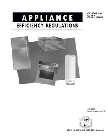
(NOTE: The Heater is delivered set to display in Fahrenheit. For a Centigrade display, see 7:3 Commissioning Section of Installation Instructions)Pool Temperature Mechanical StopStop – This can be used to obtain a repeatable settingand to limit maximum pool temperature. To set, loosenthe screw, adjust as required and then re-tighten.Pool Temperature DisplayDisplay - Normally shows the actual Pool Temperature,but also displays the Setting Temperature and a Setting Dot lit whilst being adjusted. The display is alsoused for commissioning and diagnostic purposes.Heating Demand LED - GREEN(Only in use when heating system connected)Off - There is no Heating Demand , heating is switchedoff.On - There is a Heating Demand, heating is on but notyet up to temperature.Flashing - The Heating Demand is met , heating is up totemperature.Lockout - Oil? LED - REDOn - Lockout - Oil? - This indicates that the burner cannot fire, the probable cause is lack of fuel oil. Check theoil tank. After 3 minutes press the Button on the frontof the Burner to reset. If the problem persists consultyour Service Engineer.Boiler Overheat LED - REDOn - Boiler Overheat - This indicates that the Heater hasoverheated and shut down. See Press to Reset Buttoninstructions below.Press to Reset ButtonPress - Press Reset Button when boiler has cooled down.If the problem persists consult your Service Engineer.Automatic Frost ProtectionThe Heater will automatically run a Frost Protection routine if the temperature falls below 3 C (37 F). The PoolTemperature Display will show 0 C. This will include theuse of the Pool Pump if connected to the Heater.1:7 Re-PressurisingHeating Temperature Control Knob(Only used when heating system connected)Off - There is no Heating Demand, heating is switchedoff.Normal - Normal setting for heating, it can be adjustedlower if required.(NOTE: Supplied set for Pool Priority. It will satisfy thePool Temperature before supplying full Heating. Tochange the priority, see 7:3 Commissioning Section ofthe Installation Instructions)Connect a Mains Water supply then connect the freeend of the braided flexible hose (the Filling Loop) (seeFig.2:1b) to the incoming mains connector.Filter LED - YELLOWOn - Pool Filter Blocked - Insufficient pressure, possiblydue to a blocked pool filter. The heater will not run.If this option has been installed the Heater can runthe Pool Pump on its own. Turn the Pool TemperatureControl Knob to ‘Pump’, just next to Off.Open the Valve to the supply, then, slowly open the Valveon the Side Panel until the Pressure Gauge shows 1 Bar.Close both valves then disconnect the Filling Loop.1:8 Running the Pool PumpFlashing - Clean Pool Filter - The filter may require backwashing. The heater will run. Can be reset by turning thePool Temperature knob off and back on again.COH Oil Pool Heater4GB, IE
From PoolStop cockCold waterMains inletSafety OutletOil Filter& lineFig 2:1b1:9Switching the Heater Off temporarilyThe Heater may be stopped by turning the Pool Temperature Control Knob and/or the Heating TemperatureControl Knob to OFF on Control Panel. Alternatively, theHeater may be stopped by turning off the mains switchcontrolling the Heater.1:10 Switching off for the WinterTurn both Temperature Control Knobs to Off.If the built in Frost Protection is required do not isolatethe Heater from its electrical supply.If the Heater is to be shut off for the Winter, it is advisable to have it thoroughly serviced when first shut down.Thorough cleaning will minimise corrosion during the idleperiod. Remember, when the Heater is required, to ensurethat the oil supply is open before switching on.COH Oil Pool HeaterCoh180 & Coh220Burner LockoutReset1:11 Oil DeliveryAlways ensure the tank is topped up at regular intervalsrather than wait till it is nearly empty. This will avoid sludgeand water being sucked in to the burner.Where possible, it is advisable to temporarily switch theHeater off, and to keep it off for one hour after the delivery.This is to allow any sediment to settle and not be drawninto the Heater. If you do not, this could result in an inconvenient breakdown.Please ask your supplier, or the driver to notify you beforethe oil is discharged.5GB, IE
1:12 Maintenance1:14 ServicingFor normal cleaning of the outside casing, simply wipe witha dry cloth. To remove stubborn marks and stains, wipe witha damp cloth and finish off with a dry cloth. DO NOT useabrasive cleaning materials. A spray of WD40 or similar willalso help to protect it.To ensure efficient and reliable operation of the Heater itis essential that the oil burner is initially commissionedby a qualified engineer, and that an annual service is giventhereafter by an OFTEC trained and registered engineer.The Heater must be serviced at regular intervals by a qualifiedservice engineer. Failure to have the Heater serviced at therecommended intervals will invalidate the guarantee.If using Kerosine Class C2 fuel, the Heater should be servicedat twelve monthly intervals.If using Gas Oil Class D fuel, the Heater should be serviced atsix monthly intervals.1:15 Water QualityChemical imbalance can cause severe damage to yourHeater and associated equipement.Maintain the water pH between 7.4 and 7.6 and ensurethat the free chlorine levels are within the range reccommended by the chemicals manufacturer for your size ofpool.Check the Filter reglarly and keep the pool free of debrissuch as leaves and grass cuttings.All air intakes must remain clear at all times and so it is advisable to inspect and clean these areas regularly. Please refer to4:6 later in this Installation manual for further explanation.1:13 Trouble Shooting - Failure to StartIf the Burner fails to start, adopt the following procedure:1. Check that there is oil in the tank and that the supply valveis open.2. Check that the Pool pump is operating and that the Filterlamp is not illuminated.3. Check that the Heater Control Thermostat is set highenough to be “ON” and that the Pool Demand lamp is on.4. Check whether the Boiler Overheat light on the controlfascia is glowing, if so it indicates an overheat situation.Press the Reset Button once the temperature has droppedsufficiently.5. Check whether the red Lockout indicator on the ControlPanel and Burner Control box are glowing. This indicatesthat the Burner has attempted to start but has not firedsuccessfully. Press the reset button on the Control box,when released, the lights will go out and the Burner willagain attempt to start. If the Burner does not run andagain goes to lockout with red indicators glowing:····Wait three minutes.Repeat the procedure by pressing the button.Failure to start on the second attempt indicates a faultrequiring attention.Switch off the mains supply and call your service engineer.COH Oil Pool Heater6GB, IE
2: GENERAL INFORMATIONThe horizontal terminals are designed to avoid the possibility of staining outer walls through which they pass.This Manual covers Operation, Installation, Commissioning and Maintenance of the Oil Fired Pool Heaters.2:4 COMMISSIONING2:1 INTRODUCTIONThe Pool Heaters are :· Designed for heating pools and Spas by utilising aninternal water to water heat exchanger.· Incorporates its own sealed systemcomponents; pressure vessel, filling loop, safetyvalve, and pressure gauge.· Can also be used for space heating.· Supplied with a manual reset limit thermostat.· Suitable for new installations and for replacing existing Heaters.· Include an internal thermostatic bypass to maximisethe life of the heat exchanger.All models are supplied as standard with a low levelhorizontal firing Oil Burner suitable for connection to aconventional flue.Note: The nozzle on this appliance is only covered by a 1year guarantee.2:2 PATENTSThe internal baffling system is subject to pending PatentApplication No. GB 9409095.82:3 FLUE OPTIONSThe Heaters are designed to operate with high efficiencycompliant with Section L of the Building Regulations,clean combustion, and low noise levels.Choice of flue systems are as follows:· For connection to a conventional flue.· Low level balanced flue, left, right or rear.· Outdoor.· Vertical Balanced flue.See Section 9:2 for parts/accessories detail.The tested balanced flue terminal and connection affordsan adequate supply of air for combustion and equalisation of pressure between exhaust and intake as requiredfor operation under unfavourable wind conditions.Balanced flues are supplied in a carton that includes ALLparts for a balanced flue installation.COH Oil Pool HeaterIt is essential in the interest of Heater efficiency andreliable performance that once the Heater has been installed it is first commissioned by a qualified engineer.If an engineer is not known, The Manufacturer will bepleased to provide details of an OFTEC*approved commissioning and servicing engineer fromtheir list of approved engineers.See Section 7 for Commissioning Procedure.It is the responsibility of the Installerto ensure that the Heater iscommissioned by an OFTEC*Registered Commissioning Engineer.*The Oil Firing Technical Association for the PetroleumIndustry, Banstead, Surrey Tel: 0845 6585080.2:5 SAFETYREAD THE HEALTH AND SAFETY INFORMATION ONTHE INSIDE FRONT COVER OF THIS MANUAL.Should you wish to remove ordismantle any covers or parts of theHeater for cleaning or maintenanceALWAYS FIRST SWITCH OFF THEELECTRICITY SUPPLY.1. On no account should any part of the Heater or itsFlue be modified.2. The wiring of the control panel should be as thewiring diagrams included in this Manual. Wiringshould not be tampered with, modified or changedfor any reason.3. Only use The Manufacturer’s replacement parts.Noncompliance with the above will invalidate theGuarantee.7GB, IE
3: TECHNICAL DATA3:1 LIQUID FUELSThe Pool Heaters will burn liquid fuels complying withBS2869 Part 2 1988 Classes C2 and D as specified in theCode of Practice for Oil Firing BS5410 Part 1.Class C2 (Kerosine)This fuel is suitable for all models. Burners are suppliedwith the appropriate nozzle and pump pressure as standardfor this fuel.They are set for the stated output. Details of all nozzlesizes and pump pressure for all Heaters are shown on thefollowing pages.Class D (Gas Oil)All models, can be adapted to burn Class D Gas Oil. Theadaptation requires the alterations as detailed in thedatatable 3:6.2.The use of Class D (Gas Oil) for low level discharge of combustion gases is NOT permitted under any circumstances.(Ref: Oftec Technical Book 1).3:2 HEATER TECHNICAL DETAILSMaximum Heater working pressure3 Bar (Class 2)30.6m Water HeadMaximum hearth temperatureless than 85 CMaximum side panel temperature above room.less than 35 CMinimum Conventional flue draught at Heater flue outlet0.035”w.g. (8.75N/m²).Maximum Conventional flue draught at Heater flue outletWater Resistance with 11 C temperature rise across the HeaterRecommended Filling PressureExpansion VesselFusesHeaterControlPool Pump Output, maximum0.15”w.g. (37.5N/m²).0.3m (1ft) wg1 bar4 litres,pre-charge pressure 1 bar5 Amp250mA Anti-surge glass LRC3 Amp, 230V3:3 BURNER DETAILSBurner - Reillo 40, 443T58, 459T55, 464T55. and RDB3 489T50Manually adjustable air regulator. For further details of the burners, refer to the data sheets supplied in the literature pack.3:4 ELECTRICSElectrical Supply 230v., 1 Ph., 50Hz.All wiring to the supply and all system components external to Heater must comply with the latest edition of BS7671IEE Wiring Regulations. This appliance must be effectively earthed and connection to the supply must be through adouble pole isolating switch.Note: Pool Heaters with Outdoor Flue Kits.IMPORTANT: THE OIL POOL HEATER IS SUPPLIED WITH A 13 AMP PLUG, THIS SHOULD NOT BE USED OUTDOORS. ENSURE POWER SUPPLY IS IN ACCORDANCE WITH I.E.E. REGULATIONS AND ANY LOCAL REGULATIONS WHICH APPLY.COH Oil Pool Heater8GB, IE
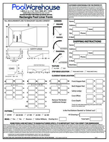
3:5 DIMENSIONSBDHCGFlueCentre LineFAFig onmmWaterContentlitresWeightEmpty 3*Conventional flue sizes ** G Grundfos, W Wilo3:6 COMMISSIONING DATA3:6.1 Class C2 Kerosine Oil, Riello Burner.ModelOutputBurnerPumpAirFiringCO² %SmokeFlue GasNozzlePressureShutterRate l/h /- 0.5%US/GPHApproxkWBtu/hTypeHead/ AnglBarpsiTempºCx .0011.50 -124028070.0239490T5122.25x60W7.51108.56.5311.50 -1250COH Oil Pool Heater9GB, IE
3:6.2 Class D, Gas OilNOTE: Low Level discharge is NOT allowedModelOutputBurnerNozzlePumpAirFiringCO² %SmokeFlue GasUS/GPHPressureShutter Rate l/h /-0.5%kWBtu/hTypeHead/ AngleBar psiApproxx .55.8211.50-1240280Not AvailableGas Oil Conversion ComponentsModel NozzlePre-HeaterConversion Kit110SPCOH2/009 SPCOH2/008Not required180 SPCOH2SPCOH001Not required220 SPCOH26Not requiredNot required280Not AvailableBottom BaffleAs SuppliedAs SuppliedAs Supplied4: INSTALLATION4:1 STANDARDS & REGULATIONSThe installation of the Heater must comply withlatest edition of :BS 5410: Oil InstallationsPt 1under 44kWPt 2over 44kWBS 5449: Forced circulation hot water centralheating systems for domestic premises.BS 4543: Pt. 1 & 3 Factory made insulated chimneys.BS 7671: Electrical Wiring Regulations.BS 7593: Treatment of water in Hot Water heating systemsBUILDING REGULATIONS.Part J & G England and WalesPart F Section lll ScotlandPart L Northern IrelandThe Control of Pollution (Oil) RegulationsOil Heaters should be installed in accordance with goodpractice as recommended by OFTEC (Section. 2:4).4:2 HEATER CONTROLThis Heater uses a control specifically designed for itand it has the following features:A Frost Thermostat which runs the Internal and PoolPump at 3 C or below but then fires the Heater alone ifthe temperature has not risen sufficiently.A Return Thermostat operating an internal bypassfor condensation reduction.An Over Temperature Thermostat (Overheat).Burner Control with Lockout.Internal Pump control with run on.Pool Pump control with run on and out-of-season exercise. (Requires external contactor)Pool Temperature and Setting display. Engineer selectable C or F.User Indicators for Pool, Heating, Lockout, Overheat,and Service.Engineer indicators of all switched outputs for simplediagnosis.Priority selection of Pool or Heating. Engineer selectable.Memory of: Filter, Overheat and Lockout occurrences.Sensor failure detection and indication.Control self checking with fault indication.For more detail see the Commissioning (7:1) an FaultFinding (10:1) sections.A highly accurate Pool Thermostat , 16 C to 41 C (60 Fto 106 F)A Boiler Thermostat. Fixed for Pool, 84 C, variable forHeating 60 - 82 C.COH Oil Pool Heater10GB, IE
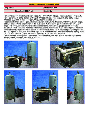
4:3 INSTALLATION WIRINGThe designs below are in order of preference, the CCP02 being the easiest, quickest and most comprehensive solution.DESIGN#Utilising the CCP02 "Quick Fit" Oil Pool Heater ControlLNE1Takes full advantage of all the features of the CertikinCCP02Oil Pool Heater. Provides the fastest installationLightsUp to 6APool Pump control providing overrun and Frost Protection action.Certikin Mk2 Oil Pool HeaterPool PumpUp to 16ALOR, Certikin Condensing 100 Plus, Pool HeaterTrip HTRPermanent Live HTRPool DemandMore than 3A HTRPool PumpUp to 3ANPool PumpT.S Time switchHTR Oil HeaterNRELAYRated tosuit pumpLTrip HTRPermanent LiveT.S3Optional connections for Lights and Space Heating all provided.OR, Certikin Condensing 100 Pool HeaterT.S2NOTESN HTRPool DemandTakes full advantage of all the features of the CertikinOil Pool Heater. Considerable installation time.Pool Pump control providing overrun and Frost Protection action.Optional Space Heating only available with more wiring.Optional Lighting only available with more wiring.IMPORTANT: Remove link, Live to Pool Demand, in HeaterLimited application of Certikin Oil Pool Heater.Moderate installation time.No Pool Pump control, Overrun or Frost Protection action.Optional Space Heating only available with more wiring.Pool PumpT.S Time switchHTR Oil HeaterOptional Lighting only available with more wiring.IMPORTANT: Remove link, Live to Pool Demand, in HeaterTripL4T.S HTRPermanent Live HTRPool DemandNNon-preferred application of Certikin Oil Pool Heater.Moderate installation time.No Pool Pump control, overrun or Frost Protection action.Optional Space Heating only available with more wiring.Pool PumpT.S Time switchHTR Oil HeaterCOH Oil Pool HeaterOptional Lighting only available with more wiring.11GB, IE
Non return valvePumpNon return valveZone ValveHeater ExpansionVessel4 litresHeater ExpansionVessel4 litresPumpExpansion vesselHeater ExpansionVessel4 litresPumpExpansion vesselHeaterHeaterSecond water 2 waterHeaterheat exchangerwith Aquastat or similar3 Way ValvePool Plus Heating and Hot WaterPool Plus HeatingPool Plus SpaNB: Add extra Expansion vessel to suit new system volume.Fig 4:3a4:4 IF COMBINED WITH A HEATING SYSTEMThe Controls provide a water temperature control foruse with a heating system, the Heating Demand Knob.It requires an electrical supply for Heating Demand tobe connected as shown in the Wiring diagram and apipe circuit to be connected to the two rear tappings ofthe Heater in place of the Air Vent and Drain.It is essential that an additional Expansion vessel isadded for the additional system volume.Depending upon the Priority set (See commissioning,7.1) the Pool or Heating will be brought up to temperature first.The Heating System should be installed in accordancewith current good practice as advised by HVCA.Typical circuits are as follows.4:5SITING & POSITIONINGConsideration must be given to the following points.1.Noise may be accentuated by the installation insmall rooms or recesses with hard or hollow stud wallsurfaces. Due consideration to the siting of Heatersshould be given.2. Some individuals may be particularly sensitive toeven low noise levels and this should be discussedbefore installation.3. The type of chimney, position relative to the Heaterand whether a draught stabiliser is to be fitted mayaffect sound level in the room.4. All models are serviced from the front and top. Aspace of 500mm (18”) in front and above the Heatershould be available.COH Oil Pool Heater5. Any kitchen work top above the Heater must beremovable for service access.4:6THE HEARTHAll models have a Hearth Temperature of less than 85 C.The Heater requires a level hearth to stand on whichshould comply with the Building Regulations.If the Heater is to stand on a floor made of combustiblematerial then protection between the Heater and the floorshould be provided by means of non-combustible material.Consideration should be given to the weight of the Heaterand the Building Regulations regarding floor loading.The filled Heater weight can be found in 3:5.Advice should be sought from your local Building ControlOffice if there is any doubts regarding the floor supporting the Heater.4:7 OIL STORAGE4:7.1 Oil TankConsideration to the access by fuel delivery lorries shouldbe given when positioning the oil tank.Tank positioning should be in accordance with BS 5410Part 1 and OFTEC Technical Book 3.In the interest of most economical deliveries the Oil Tankshould be of 3,000 litres (600 gallons) capacity.12GB, IE
It should be completed with the following:1.2.3.4.Sludge Cock - on steel tanks.Outlet Valve.Contents Indicator.Hinged Fill and Vent Cover or a separate Fillconnection and Vent. The Fill and Vent shouldbe suitably capped to prevent ingress ofwater or fitted with return bends4:7.2 Steel TanksTanks should be mounted on suitable supports, if theseare of brick or blocks, a damp proof membrane should beinserted between the tank and its supports.Tanks should slope 20 mm per metre of length downwardsfrom the Oil Outlet to the Sludge Cock situated at the opposite end.4:7.3 Plastic Oil Tanks.Tanks made from plastic are now available. These should beUV stabilized for protection against sunlight, and colouredgreen. Plastic tanks do not need to stand on piers, butshould be supported across the entire base area, ideally on50 mm thick garden slabs or a concrete base. As there isonly one tapped outlet they are more suited to single pipefeed as gravity supply or with a 3K Oil Loop Deaerator wheresuction lift is required. (Part No. BS 03060)4:8 OIL SUPPLYThe oil connection points on the Heater casing are shownin the diagram Fig 7:2c in Section 7 of this manual.All joints in the Oil Lines must be oil tight and the Oil Lineshould be flushed clean before connecting to the burner.Note that no soldered joints are permissible in the oilline.4:8.1 Oil FilterAn Oil Filter is provided with the Heater. Connections are¼ BSP Female, see Fig. 4:8b, 4:8c, 4:8d, 4:8e, 4:8f, 4:8g.It is essential for reliable operation
*The Oil Firing Technical Association for the Petroleum Industry 0845 6585080. 1:5 Quick Start Check the Electricity and Oil supplies to the Heater are on. If the Pool Pump is not controlled by the Heater, turn it on. Turn on the Heater by turning the Pool Tempera-ture Control Knob clockwise to show the required Pool temperature, the Heater .