Transcription
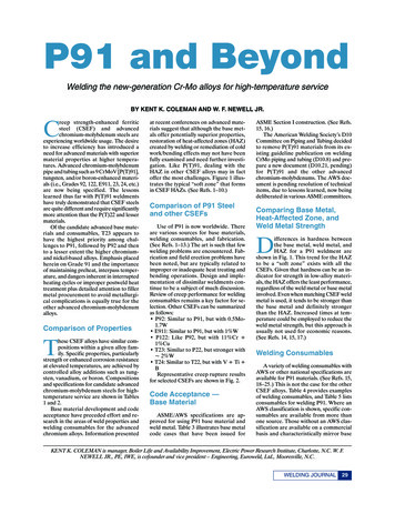
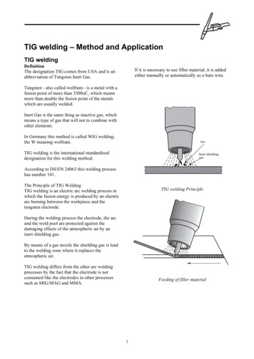
TIG welding – Method and ApplicationTIG weldingDefinitionThe designation TIG comes from USA and is anabbreviation of Tungsten Inert Gas.If it is necessary to use filler material, it is addedeither manually or automatically as a bare wire.Tungsten - also called wolfram - is a metal with afusion point of more than 3300oC, which meansmore than double the fusion point of the metalswhich are usually welded.Inert Gas is the same thing as inactive gas, whichmeans a type of gas that will not to combine withother elements.In Germany this method is called WIG welding,the W meaning wolfram.TIG welding is the international standardiseddesignation for this welding method.According to DS/EN 24063 this welding processhas number 141.The Principle of TIG WeldingTIG welding is an electric arc welding process inwhich the fusion energy is produced by an electricarc burning between the workpiece and thetungsten electrode.TIG welding PrincipleDuring the welding process the electrode, the arcand the weld pool are protected against thedamaging effects of the atmospheric air by aninert shielding gas.By means of a gas nozzle the shielding gas is leadto the welding zone where it replaces theatmospheric air.TIG welding differs from the other arc weldingprocesses by the fact that the electrode is notconsumed like the electrodes in other processessuch as MIG/MAG and MMA.Feeding of filler material1
Migration of electrons and ions in TIG weldingThe flow of electrons from the point of theelectrode takes place at a very high speed andwhen it hits the workpiece a substantial amount ofheat energy is produced.Automatic feeding of filler materialWhen the flow of ions hits the point of theelectrode there is not produced a similar amountof hear energy.The TIG ArcAs mentioned before the fusion energy in TIGwelding is produced in the arc burning betweenthe tungsten electrode and the workpiece.The total produced heat energy is distributed byapprox. 30% to the point of the electrode that isconnected to the negative pole and approx. 70% tothe workpiece connected to the positive pole.The wire feeding can be done manually ormechanically.In DC TIG welding the tungsten electrode isusually connected to negative polarity and theworkpiece to positive polarity.Alternating CurrentAlternating current is characterised by the fact thatthe voltage changes polarity a certain number oftimes, usually 100 times per second.According to the theory of electrons thenegatively charged electrons and positivelycharged ions will migrate when the arc is ignited.The electrons will migrate from the negative poleto the positive pole while the ions will travel inthe opposite direction.In the arc there will therefore be a collisionbetween the electron and the ions and thiscollision produces heat energy.2
ApplicationAdvantagesThe TIG welding process has a very large area ofapplication due to its many advantages, e.g.: It provides a concentrated heating of theworkpiece. It provides an effective protection of the weldpool by an inert shielding gas. It can be independent of filler material. The filler materials do not need to be finelyprepared if only the alloying is all right. There is no need for after treatment of theweld as no slag or spatter are produced. Places of difficult access can be welded.Areas of applicationTIG welding is often used for jobs that demandhigh quality welding such as for instance: The offshore industry Combined heat and power plants The petrochemical industry The food industry The chemical industry The nuclear industryHeat distribution at TIF weldingThe electrode has positive polarity in a semiperiod and in the same semi-period the workpieceis negative.In the next semi-period the polarity is reversed,which means that the heat energy distributes with50% on the electrode and 50% on the workpiece.Materials for TIG weldingThe most important area of application is: Welding of thin materials in stainless steels Aluminium Nickel Nickel alloysThe increasing demands to the weld quality hasmade TIG welding very popular for welding ofsmaller tube dimensions as well as root runs inboth non-alloyed and alloyed materials in heavierplates.3
The below table shows which materials can beTIG welded and the recommended types ofcurrent and hromium/nickel steelsChromiumsteelsCopper alloysNickel ype ofcurrent Electrodepolarity- - - - - Legend: DC, AC, - negative, positiveDirect current with negative polarity on theelectrode is used for TIG welding of mostmaterials.Welding aluminium and magnesium is usually notpossible with direct current. The reason for this isthat a strong layer of oxide, which is difficult tobreak through due to its high fusion point, coversthese materials.Therefore aluminium, magnesium and their alloysare usually welded with alternating current whichis capable of breaking the oxide layer.4
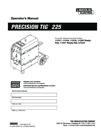
TIG Welding EquipmentMany TIG welding machines are constructed insuch a way that the power source and the TIG unitare one unit.ConfigurationIn order to handle the TIG welding process andmake it work to its full capability you needequipment consisting of different parts with theirown separate function.The TIG welding equipment chiefly consists of: A TIG torch that is the tool the welder uses tocontrol the arc. A power source which is capable of providingthe necessary welding current. A TIG unit with incorporated control systemsthat make it possible to adjust the weldingcurrent, arc initiation etc. A shielding gas cylinder with pressurereducing valve and flowmeter.1234567Cable for welding currentCable for welding currentControl cable for TIG unitShielding gasCable for welding cable for TIGtorchControl cable for TIG torchWelding cable with polarityPower source and TIG unit in one unitTIG TorchThe main purpose of the TIG torch is to carry thewelding current and shielding gas to the weld.TIG TorchThe TIG torch is constructed on the basis of thewelding handle and a torch head that is coatedwith an electrically insulated material.Example for configuration of welding equipment5
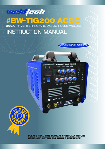
The torch handle is usually fitted with a switch toturn the welding current and the shielding gas onand off.The electrode collet is split in order it cancompress to fit tight around the electrode whenthe electrode cap is tightened.1.2.3.4.5.6.7.8.9.In order to avoid a too heavy current load on theelectrode the torch is constructed in a way that thecurrent transfer to the electrode takes place veryclose to the electrode point.Torch headHandleControl switchElectrode capSealing ringElectrode colletHeat shieldCollet bodyGas nozzleDrawing of TIG welding torch6
The long torch cap, shown on the drawing, can beexchanged by a shorter version in order for thetorch to be used at restricted areas.Cooling of the TIG TorchSome torches are constructed in such a way that itis the flowing shielding gas that cools the torch.However, the torch also gives off heat to thesurrounding air.However, the cap is usually so long that it cancover an electrode of normal length.Other torches are constructed with cooling tubes.Water-cooled torches are mainly used for weldingwith larger current intensities and AC-welding.TIG torches are available in many different sizesand designs according to the maximum requiredcurrent loads and the circumstances under whichthe torch is to be used.Usually a water-cooled TIG torch is smaller thanan air-cooled torch designed to the samemaximum current intensities.The size of the torch will also depend on itscooling capacity during welding.7
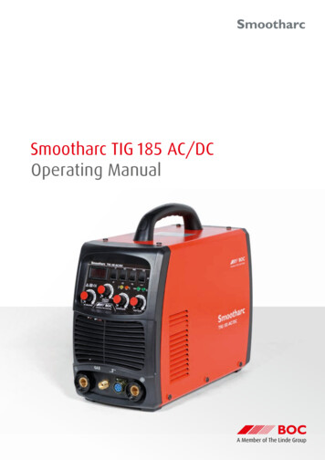
Some of the new TIG torches also have a triggeron the torch handle for control of the weldingcurrent during welding.Gas LensAnother type of gas nozzle is the gas lens which isconstructed in a way that the shielding gas passesthough a wire grid in order to make the flow ofgas more stable at a longer distance.The Gas NozzleThe function of the gas nozzle is to lead theshielding gas down around the welding zone andthereby replace the atmospheric air.The gas nozzle is screwed onto the TIG torch so itcan be exchanged if required. It is usually made ofa ceramic material able to stand the massive heat.The size of the gas nozzle is often indicated by anumber that refers to the interior diameter of theorifice in 1/16”.ExampleA gas nozzle no. 4 has an interior diameter of4/16” corresponding to 6.4 mm.Flow of shielding gasThe advantage of the long gas flow is the fact thatthe electrode can have a longer stick-out thusallowing the welder to have a better view of theweld pool. By means of a gas diffuser it is alsopossible to reduce the consumption of shieldinggas.The Power SourceThe power sources for TIG welding generallyhave an open circuit voltage of about 70 to 80 V.For welding with direct current a power source isused that rectify the alternating current of themains supply of 400 V to the suitable output forthe TIG process and at the same time changes thecurrent intensity to the level set by the welder onthe welding machine.Common gas nozzle and gas nozzle with gas lensModern welding machines are capable of weldingof welding either in a DC mode or some unitsprovide both AC and DC modes.8
TIG BoxesAnother type of control of the ignition can be anincorporated unit which is capable of limiting theshort-circuit current at the moment of ignition, sothat when welding starts the point of the tungstenelectrode can be placed directly on the workpiecewithout sticking. The control then increases thewelding current intensity when the electrode islifted from the workpiece thus igniting the arc.The control system of the TIG equipment can beeither very simple or very advanced with manydifferent functions.In its most simple version only the weldingcurrent is controlled and the shielding gas isturned on/off by a small valve on the TIG torch.The more advanced TIG boxes are capable ofcontrolling the shielding gas so it is lead to thewelding place before the arc is ignited, anddelaying the interruption of the shielding gas afterthe welding current is cut off.This kind of control has several names as forinstance LIFTARC or LIFTIG.This means that the tungsten electrode and theweld pool are also protected from the atmosphericair during the cooling period.Furthermore, the TIG box usually has an ignitionfacility in order to avoid having to scratch theelectrode against the workpiece and thusdamaging the electrode point.Ignition with the LIFT method.Other possibilities for control of the ignition are: Slope control that makes it possible to preprogram the increase of the welding currentwhen welding starts and the decrease of thewelding current when welding stops. Slopecontrol is especially important at the end ofwelding to help eliminate porosity and shrinkholes.This ignition facility can be a high frequency unit(HF) which increases the frequency to 2 to 4million periods per second and the voltage toseveral thousand volts.The high frequency and the voltage make itpossible to produce a spark between the electrodepoint and the surface of the workpiece thattransfers the arc.Slope facilityCurrent pulsation means that two welding currentlevels are pre-programmed. These are pulsecurrent and base current.The base current is only large enough to maintainthe arc.The fusion of the base material then takes placewhen the pulse current is present and the weldpool cools when the base current is present but thearc is maintained.High frequency ignition9
The pulse and base current periods are alsocontrollable.When welding is done with pulsing welding modethe weld is in principle a row of spot weldsoverlapping to a larger or smaller extentdepending on the welding speed.Example of a weld with pulsing arcMany double-current machines are equipped witha control function which makes it possible tomodify the curve of the alternating current inorder to make more square, and also modify thebalance between the positive and the negativesemi-periods.Example of a modified AC curveThese control possibilities are very advantageouswhen TIG welding aluminium, magnesium andtheir alloys.10
TIG Welding – Grinding of Tungsten ElectrodesThe most commonly used types of tungstenelectrodes are: Pure tungsten is marked with green colour.This electrode is especially used for ACwelding in aluminium and aluminium alloys. Tungsten with 2% thorium is marked with redcolour. This electrode is mostly used forwelding of non-alloyed and low-alloyed steelsas well as stainless steels. Tungsten with 1% lanthanum is marked withblack colour. This electrode is equally suitedfor welding of all TIG weldable metals.Electrodes for TIG WeldingFor TIG welding the applied electrode is mainlymade of tungsten.Pure tungsten is a very heat resistance materialwith a fusion point of approximately 3,380oC.By alloying tungsten with a few per cent of ametal oxide the conductivity of the electrode canbe increased which has the advantage that it canthereby resist a higher current load.The alloyed tungsten electrodes therefore have alonger lifetime and better ignition properties thanelectrodes of pure tungsten.Electrode DimensionsTungsten electrodes are available in differentdiameters from 0.5 to 8 mm.The most frequently used metal oxides used foralloying of tungsten are: Thorium oxideThO2 Zirconium oxideZrO2 Lanthanum oxideLaO2 Cerium oxideCeO2The most frequently used dimensions for TIGwelding electrodes are 1.6 - 2.4 - 3.2 and 4 mm.The diameter of the electrode is chosen on basis ofthe current intensity, which type of electrode thatis preferred and whether it is alternating or directcurrent.Colour Indications on TungstenElectrodesGrinding AngleAs the pure tungsten electrodes and the differentalloyed ones look the same, it is impossible to tellthe difference between them. Therefore a standardcolour indication on the electrodes has beenagreed.An important condition for obtaining a good resultof TIG welding is that the point
TIG welding – Method and Application TIG welding Definition The designation TIG comes from USA and is an abbreviation of Tungsten Inert Gas. Tungsten - also called wolfram - is a metal with a fusion point of more than 3300oC, which means more than double the fusion point of the metals which are usually welded. Inert Gas is the same thing as inactive gas, which means a type of gas that will .