Transcription
INSTRON 5582 UNIVERSAL TESTER“Fat Tony”OperatingInstructions
I N S T R O N5 5 8 2U N I V E R S A LT E S T E RTable of ContentsIntroduction11SAFET YSafety Hazards1Safety Precautions12BACKG ROUNDBackground Information2The Tension Test2Metals2Polymers4The Flexure (Bend) TestCeramics55The Compression Test6References63OPERA TIONGrips Setup7Software Setup7Running the Test8Helpful Hints111
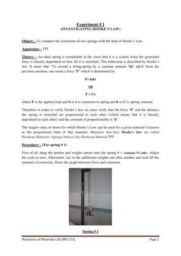
I N S T R O N5 5 8 2U N I V E R S A L1T E S T E RIntroductionThe Instron 5582 Universal Tester is a state-of-the-art testing machine that features a 100kN load frame, a variety of specimen fixtures, several strain gauge extensometers, andMerlin software that is loaded with data collection and analysis features.Specimen Geometry. The Instron universal tester can handle a variety of specimen geometries.If you can find appropriate test fixtures in our supply cabinets, or design and fabricate your owntest fixtures, you can probably test your sample.Test Fixtures. Our current stock of test fixtures includes the following: 3-Point Bend Setup for flexure testing. Platens for compression testing. Wedge Grips with various faces (for different specimen geometries) for tension testing.SafetySafety Hazards Fracture of brittle materials may result in projectiles.The Instron Universal Tester is capable of applying forces that can easily crush hands or otherbody parts, and the machine does not know or care if it’s testing a steel rod or your fingers.Safety Precautions Always wear eye protection when working with or around the universal tester.Move the yellow and black limit switches on the left column to positions close to thecrosshead when changing fixtures to prevent accidental crushing of you or your specimen.Keep all limbs clear of the machine when running tests.Stand away from the instrument while a test is running.Be careful when removing or adjusting the specimen grips. Some grips are quite heavy, andthey parts of the grips may become loose and fall if improper adjustments are made.1
I N S T R O N5 5 8 2U N I V E R S A LT E S T E RBackground Information2A vast number of standardized tests are available for the measurement of mechanical properties.Three of the more common tests that may be easily performed with the Instron Universal Testerare tension testing, compression testing, and flexure testing. Each of these tests is used todetermine how a material will respond to a particular type of loading. Depending on the type oftest, the relevant output from the Instron may include load, displacement, stress, and strain data.The Tension TestNOTE: The following background text is taken directly or adapted from the Uniaxial Tension Testingsection of ASM Handbook, Volume 8 Mechanical Testing and Evaluation.The tension test is one of the most commonly used tests for evaluating materials. In its simplestform, the tension test is accomplished by gripping opposite ends of a test item within the loadframe of a test machine. A tensile force is applied by the machine, resulting in the gradualelongation and eventual fracture of the test item. During this process, force-extension data, aquantitative measure of how the test item deforms under the applied tensile force, usually aremonitored and recorded. When properly conducted, the tension test provides force-extensiondata that can quantify several important mechanical properties of a material. These mechanicalproperties determined from tension tests include, but are not limited to, the following: Elastic deformation properties, such as the modulus of elasticity (Young's modulus) andPoisson's ratio,Yield strength and ultimate tensile strength,Ductility properties, such as elongation and reduction in area, andStrain-hardening characteristics.See Chapter 6 of your textbook for equations and information on analysis of stress/strain curves.The material characteristics determined from tension tests are used for quality control inproduction, for ranking performance of structural materials, for evaluation of newly developedalloys, and for dealing with the static-strength requirements of design. Tension tests are generallyperformed on metals and polymers. Ceramic materials, which are generally brittle, are difficult togrip in tension without causing damage or fracture, so flexure tests are more commonly used forceramic materials.MetalsPlastic deformation in metals is the result of the motion of large numbers of linear defects, ordislocations, in the material. The mechanical properties and stress-strain response of metals2
I N S T R O N5 5 8 2U N I V E R S A LT E S T E Rand alloys are largely a result of the ease at which dislocations can move in the material. Ifdislocation motion in a particular metal or alloy is difficult, the metal will experience very littlestrain before brittle fracture occurs. If dislocation motion is easy, the material will behave in aductile manner and exhibit a large amount of plastic deformation prior to failure. Thechemical composition, mechanical processing, thermal processing (heat treatments), and thepresence of defects will all affect the microstructure and mechanical properties of metals andalloys.Your instructor will provide a number of different metals and alloys ready for tensile testing.The cylindrical metal alloys are machined in accordance with ASTM E8 (“Standard TestMethods for Tension Testing of Metallic Materials”), a commonly-used standard that outlinesspecimen geometries and specific procedures for tensile testing. This standard by no meansdictates the only sample shape that can be tested in the Instron, it is simply the industrystandard for formal materials testing.Alloy numbers and fabrication/processing information for the alloys are shown in thefollowing table:MetalAlloy 110 copperAlloy 360 brassGrade 2 titanium6061 aluminum2024 aluminumGray cast iron304 stainless steel1045 steel1018 or 1020 steel1018 or 1020 steelFinish/TemperCold rolledCold rolledT6T6CastCold RolledHot RolledCold DrawnHot Rolled3
I N S T R O N5 5 8 2U N I V E R S A LT E S T E RPolymersThe mechanical properties and stress-strain response of polymers are largely a result of thechemical structure of the polymer. Polymers exhibit three basic types of stress-strainbehavior: (i) “brittle” stress-strain behavior, described by high strength but very low strain tofailure (generally observed in glassy or amorphous polymers), (ii) “plastic” stress-strainbehavior, described by moderate strengths and relatively high elongations to failure (generallyobserved in semicrystalline polymers), and (iii) “elastomeric” stress-strain behavior, describedby extremely high strains and very low stresses at failure (generally observed in rubbers).Your instructor will provide a number of different polymers ready for tensile testing. Therectangular dog-bone samples are machined in accordance with ASTM D638-02a (“StandardTest Methods for Tensile Properties of Plastics”), a commonly-used standard that outlinesspecimen geometries and specific procedures for tensile testing. This standard by no meansdictates the only sample shape that can be tested in the Instron; it is simply a common,accepted standard for formal polymer tension testing.Available polymers and recommended processing information are shown in the followingtable:4
I N S T R O N5 5 8 2U N I V E R S A LT E S T E RPolymerHigh Density ene (Teflon)PolyesterPolystyrenePolymethyl methacrylatePolycarbonatePolyvinyl chlorideAcetal (Delrin)Acrylonitrile butadiene dCrosshead -205-205-205-20The Flexure (Bend) TestA typical application of the flexure test is to gain strength and ductility information on a brittlematerial, such as a ceramic. Flexural testing is preferred for brittle materials because surface flawson the material or the grip of the testing machine can accidentally create unwanted cracks thatmay affect test results. The flexure test creates an environment in which strength can bemeasured without having to worry as much about surface flaws.CeramicsProbably one of the most distinguishing mechanical features of ceramics is their highcompressive but low tensile strength. Since most ceramics are formed from ionic andcovalent bonds, dislocation motion does not play a significant role in their room temperaturestrength as it does with metals. Instead, the mechanical properties of ceramics have muchmore to do with the number of flaws within the material, as well as the types of forces exertedon the material. Of note are the incredibly high compressive strengths of most ceramics –usually an order of magnitude higher than their tensile strengths. Further, most ceramics arevery brittle under tensile stresses. In general, temperature has much less of an effect onceramics as it does on metals and polymers.Many types of flexural testing are possible, but the most common is the 3-point flexure test, inwhich a sample is set upon two supports, and a force is applied directly between the two supports.Since the forces exerted on a material are different from a tensile test, the calculations necessary tofind strength and ductility are also different. More information about calculating flexural strengthand the 3-point flexure test can be found in Chapter 6 of your textbook.5
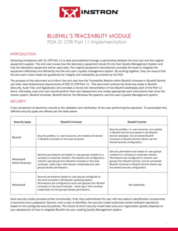
I N S T R O N5 5 8 2U N I V E R S A LT E S T E RAn illustration of a 3-point flexure test of a ladder. Note thatthe many surface inconsistencies would make it very difficult toperform an accurate tension test of this specimen.The ASTM D5023-01 standard sample for a flexure test is a 2.5 x 0.5 x 0.125 in. rectangular bar.While these exact dimensions are not required, the length of the sample needs to be long enoughto prevent the interference of any external forces during the test. Thus, at least 10% of thespecimen should hang over each of the two end supports. It is a good idea to consult the ASTMstandard for specific guidelines for nonstandard test samples.The Compression TestCompression testing is generally used to evaluate materials at high strain and temperatures levels,as well as highly brittle materials for which creation of a standard tensile specimen is very difficult.Further, it can also be used to simulate more realistic stresses on materials that will be used forspecific purposes, such as concrete. Unlike a tension test, a compression test is performed byexerting an inward force on the material, resulting in a plastic deformation of the material intosomething shorter and wider than its original form. One major benefit to a compression test isthat the sample material ideally will not experience any sort of mechanical failure – there will beno weakening such as necking experienced during the test. Unfortunately, compression tests arenot always successful in this regard. Sometimes, failure such as buckling and barreling will weakenthe specimen and create a non-uniform distribution of stress on the sample. More informationon both of these phenomena can be found in Volume 8 of the ASM Handbook.The standard test specimen for a compression test is a simple cylinder. The cylindrical sampleshape provides an advantage over tension testing, since the specimen is generally easier to makeand requires less material. The following table, taken from ASTM E9 (“Standard Test Methodsof Compression Testing of Metallic Materials at Room Temperature”), shows standard diameterto length ratios for compression test samples. Note that these recommendations are for metallicmaterials. Appropriate sample sizes for compression testing of polymers, ceramics, andcomposites may be found in other standards.6
I N S T R O N5 5 8 2U N I V E R S A LT E S T E RReferences Callister: Sections 6.2, 6.3, and 6.6 for metals; sections 15.2 - 15.4, 15.7 - 15.9 for polymersAskeland: Sections 6.2-6.6 for mechanical testing and stress/strain behavior; 15.1-15.2 forceramicsASM Handbook Volumes 1 and 2 for MetalsASM Handbook Volume 8 for Mechanical Testing MethodsASTM D5023-01, D638-02, E8, .gif for the elephant picture7
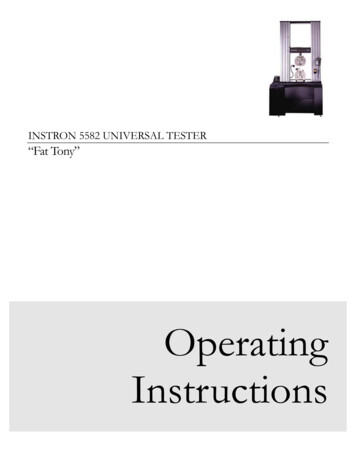
I N S T R O N5 5 8 2U N I V E R S A L3T E S T E ROperationStartup1. If the appropriate sample grips are already installed, skip to Step 6.Grips Setup1. If the appropriate sample grips are already installed, skip to Step 6.2. If necessary, raise or lower the crosshead to an appropriate position by pressing the up anddown arrows on the load frame control panel.3. Change fixtures according to the test you wish to run – wedge clamps with various faces for4.5.6.7.tension tests, three point bend fixtures for flexural tests, compression platens for compressiontests. Use appropriate adapters and pins for your fixturing.After you have attached the fixtures with pins, tighten the knurled collars at the attachmentpoint of the grips. The pins should now be tight, and they should no longer slide in and outwith finger pressure.Attach wire clips around the pins to keep then from sliding out during the test.Raise or lower the crosshead to an appropriate position for sample loading. Use the up anddown arrows on the load frame control panel for large displacements. Use the scroll-wheelfor fine motion.SAFETY: Set the crosshead limit switches (the yellow and black sliders on the left column)to appropriate positions to prevent the crosshead from moving too far up or down. If youaccidentally cause the crosshead to hit one of the limit switches, the machine willautomatically stop.Software Setup1. Open the software by double-clicking the Merlin icon on the desktop.2. If you see the desired test method in the list, click on it. Otherwise, click the Merlin button atthe bottom right to open other test methods. You should see a screen that looks like this:8
I N S T R O N5 5 8 2U N I V E R S A LT E S T E R3. Select the Test Type (tension, flexure, etc.) at the lower right.4. Select the procedure File Name (example: selection of test type Tension, file name:PLASTIC1.MTA will open a test method designed for tension testing of polymers withoutthe use of an extensometer).Running the Test1. If you have successfully opened a test method, you will see a screen that looks something likethis:9
I N S T R O N5 5 8 2U N I V E R S A LT E S T E ROVERVIEW OF THE SCREEN: The two top left buttons numbered “1” and “2” correspond to the “1” and “2” buttonson the load frame control panel. These buttons are programmable via the software. The monitor-looking button at the top controls the view on the screen. The three top right buttons are used to calibrate and balance (zero) the extensometer,load cell, and crosshead position. The buttons along the right edge are used to (i) control the crosshead and (ii) set the testand data analysis parameters. The large digital readouts show live signals of load, crosshead position, and (sometimes)extensometer strain. The default display for many test methods is just the load andcrosshead position. To add a third or fourth live signal display, click on the monitorlooking button at the top and adjust the display parameters.Set Test Parameters2. Click on the traffic light icon on the right side of the window. The following settings areadjusted under the traffic light menu:Pretest – unless you want to apply a pre-load, all boxes should be uncheckedTest – set crosshead rate (Ramp 1). 0.25 in/min is a good speed for metals.Data – set the data capture to “Manual” and an appropriate time interval (decent valuesare 500 ms for slow tests, 50 ms for longer tests)Strain – if you’re using the extensometer, set Source to “Strain 1” and use your goodjudgment in setting a strain value for extensometer removal (you don’t want the samplebreaking with the extensometer attached damage to the device could result)Close the window after making your changes.Set Sample Parameters3. Click on the tensile specimen icon (blue dogbone specimen) on the right side of the window.The following settings are adjusted under the tensile specimen menu:Define – use this menu to specify the specimen name and specimen geometry (circular)Specimen – use this menu to indicate the specimen name and initial dimensions.Notes – write some humorous notes to yourself or your teammates, if you like.Bend Fixture (flexure testing only) – enter the fixture type and support span.Close the window after making your changes.Load the Sample4. Be sure you have measured and recorded the specimen dimensions before placing thespecimen in the grips (see previous step).5. Load your test specimen in the grips. Tension: If you are running a tension test with the wedge grips, insert your specimeninto the top grip first and tighten the grip. Then use the crosshead controls to lower thespecimen into the bottom grip. Tighten the lower grip. Flexure: Adjust the lower flexure fixture to an appropriate span. Place the specimen onthe lower fixture and align. Lower the crosshead until the top fixture is just above yourspecimen.10
I N S T R O N5 5 8 2 U N I V E R S A LT E S T E RCompression: Center and align your specimen. Lower the crosshead until the topfixture is just above your specimen.Attach the Extensometer6. Attach the extensometer to the specimen, if necessary – ask your course instructor or TA forspecific instructions on attaching the extensometer.Start the Test7. Zero the Load, Extension, and Strain 1 readouts by clicking on the icons at the upper right ofthe window. Load: click on the Balance button then click Done at the right of the dialog box. Extension: click on the Reset Gauge Length button then click Done at the right of thedialog box. Strain 1: if you’re using the extensometer, click on the Balance button then click Done atthe right of the dialog box.8. Start the test by pressing the “Start Test” button on the load frame control panel or the yellowplay button on the screen.9. Four ways to stop a test: If something does not go as desired or planned, the run can bestopped by pressing the red Stop Test button on the control panel, the big emergency stopbutton on the frame, jostling one of the yellow switches on the left column, or pressing thestop button on the computer.10. The graph can be monitored by pressing the button that looks like a graph on the rightsidebar. The top left button under graph lets you specify what each axis is well as units andscale. Pressing the third button on the graph display will autoscale the plot.After the Test11. On the main window (not the graph window), go to File Setup and make sure theASCII Raw Data to: option is checked. Click OK.12. On the main window (not the graph window). to go File Data End&Save. Name yourfile and save it to the hard drive. The default save directory is c:\instron\user\data.13. Carefully remove the specimen from the grips and measure the final dimensions.14. Use Olin’s web mail service, to email the appropriate data files from the hard drive toyourself. Unless you are planning to do your data analysis on the Instron machine’s controlcomputer, the most useful file is the one with the “raw” extension. The “raw” data file is awell-labeled, comma-delimited ASCII data file that works very well with Excel (be sure to tellExcel that the data are comma delimited).11
I N S T R O N5 5 8 2U N I V E R S A LT E S T E RHelpful Hints1. Be gentle whenever possible. Some pins or samples may need to be tapped with a soft mallet2.3.4.5.to get them in or out, but you should not have to muscle any part of the machine into place.If the load frame is not responding, press the button on the right side of the screen that lookslike a load frame, then press the Enable Frame button.If you wish to see the raw data, pull up a graph, then go to the graph pull-down menu, andselect data.An extensometer should be used with tension tests if accurate displacement data is desired. Ifyou don’t use an extensometer, your elastic modulus values will be off.Reasonable crosshead displacement rates for metal tests are along the lines of 2 to 3 mm/min.Polymers may be tested between 2 and 500 mm/min; in general, the greater the expectedelongation, the higher the crosshead speed. Ceramics and inorganic glasses should be testedat very low crosshead speeds, e.g., 1-2 mm/min.12
he Instron 5582 Universal Tester is a state-of-the-art testing machine that features a 100 kN load frame, a variety of specimen fixtures, several strain gauge extensometers, and Merlin software that is loaded with data collection and analysis features. Specimen Geometry. The Instron universal tester can handle a variety of specimen geometries.