Transcription
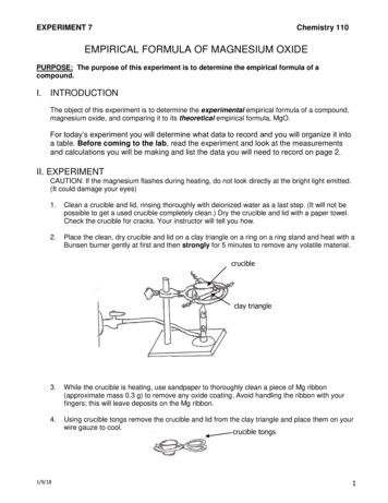
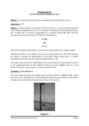
Experiment # 1(INVESTIGATING HOOKE’S LAW)Object: - To compare the extensions of two springs with the help of Hooke’s Law.Apparatus: - ?Theory: - An ideal spring is remarkable in the sense that it is a system when the generatedforce is linearly dependent on how far it is stretched. This behaviour is described by Hooke’slaw. It states that “To extend a string/spring by a constant amount ‘dx’ OR‘s’ from theprevious position, one needs a force ‘F’ which is determined byF kdxORF Cswhere F is the applied load and S or x is extension in spring and k or C is spring constant.Therefore in order to verify Hooke’s law we must verify that the force ‘F’ and the distancethe spring is stretched are proportional to each other (which means that it is linearlydependent to each other) and the constant of proportionality is ‘k’.The largest value of stress for which Hooke’s Law can be used for a given material is knownas the proportional limit of that material. Materials that obey Hooke's law are calledHookean Materials. Springs behave like Hookean Material.?Procedure: - (For spring # 1)First of all, hang the pointer and weight carrier onto the spring # 1 (contains 53 coils). Adjustthe scale to zero. Afterwards, lay on the additional weights one after another and read off theamounts of extension. Draw the graph between force and extension.Spring # 1Mechanics of Materials Lab (ME-213)Page 1
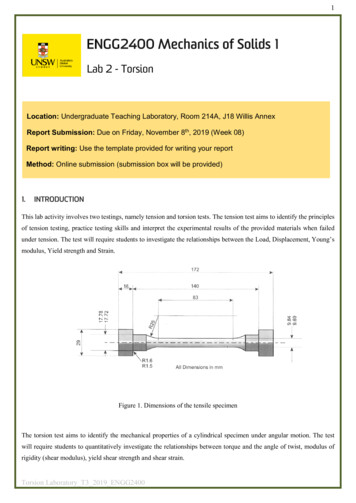
Procedure: - (For spring # 2)Hang the pointer and weight carrier onto the spring # 1 (contains 106 coils). The weight carrieracts as pre loading. The preloading is necessary in order that the coils separate from eachother. Adjust the scale to zero. Afterwards, lay on the additional weights one after anotherand read off the amounts of extension. Draw the graph between force and extension.Spring # 2Results: -Spring # 1S.NoForce (F) in NExtension (S) in mmF/S in N/mm.1.2.3.4.5.6.Mechanics of Materials Lab (ME-213)Page 2
Spring # 2S.NoForce (F) in NExtension (S) in mmF/S in N/mm.1.2.3.4.5.6.Discussion: - ?Conclusion: The quotient F/S is clearly constant for both the springs. It is also called ‘Spring Constant’and it is denoted by C. Extension spring # 1 has approximately 53 coils while extensionspring # 2 has 106 – 108 coils. The graph shows a straight line between the two variables i.e.F and S originating at zero. A greater number of coils mean a softer spring and the springconstant will be smaller. On the other hand, when the number of coils is doubled, the springconstant is halved. ?Abstract: - ?References / Bibliography: - ?QuestionsQ1 Explain the significance of Hooke’s Law?Q2 Is there any difference between Young’s modulus and Bulk’s modulus? Elaborate?Q3 Why the spring constant is smaller for the spring which has greater number of coils?Q4 Explain Hooke’s Law of elasticity?Q5 If the load is doubled, what is the effect on the spring’s extension?Q6 Enlist the parameters which is same for both springs?**************************Mechanics of Materials Lab (ME-213)Page 3
Experiment # 2PENDULUM IMPACT TESTER (25 N-m)Object:a) To study the influence of the specimen material on notched bar impact work.b) To study the influence of the notch shape on notched bar impact work.Theory:The deformation of a material can differ under different conditions of stress. For this reason,knowledge of the deformation behaviour of a material is an important criterion for evaluatingand selection a material. The phenomena of failure are different for ductile and brittlematerial because both it depends upon load conditions such as stress, strain, speed andtemperature.Two standardized tests are used to measure the impact energy i.e. the Charpy and Izod. Theprimary difference between the Charpy and Izod techniques lies in the manner of specimensupport. These are termed as impact tests because of the manner of load application.The Charpy test is carried out with the help of pendulum impact tester. In a Charpy test, anotched specimen whose two ends lie on a support is broken or bent by hammer impact anddrawn through the supports. The notched bar impact work is measured in N-m andrepresented in J (Joules). The results of the charpy test offer a reference for the properties ofthe material. However they are only valid for comparison when they are achieved with thegeometrically equivalent specimens under the same test conditions. ?Mechanics of Materials Lab (ME-213)Page 1
Apparatus: 1. Anvil. (Footing)2. Support.3. Protective Ring.4. Trailing Pointer / Maximum Indicator.5. Scale. (for 25 N-m maximum capacity)6. Hammer.7. Bottom hand lever. (for releasing hammer)8. Brake.9. Notched bar specimen.10. Safety hook. (for holding the hammer)11. Hammer lock.?Material & Notch Shape: MaterialSteel alloyBrassAcrylic (Optional) Notch TypeV-NotchRectangular NotchU-NotchProcedure:The pendulum impact tester must rest on a flat base. Before the experiments, an impactshould be tried without the specimen to determine if the hammer swings freely. Then, thezero point is set. The hammer must be released with both hands.The notched bar to be broken is placed in the support that is firmly screwed to the anvil. Thespecimen is positioned with the notch facing the impact and affixed to the mandrel.The specimen is either destroyed and fractures when it is hit by hammer, or it is bent by theimpact and is drawn between the stops. The applied work is indicated by the maximumindicator on the scale. The following two processes are essential.1) Holding the pendulum.2) Releasing the pendulum.First of all pull the hammer lock upwards and move the hammer as far as the stop for theaxis- the hook then engages with the bottom hand lever. Then move the hammer downwardsslightly until the upper hammer lock engages.For releasing the pendulum, pull the hammer lock upwards. Then press the bottom hand leverto release the pendulum. Record the reading.Mechanics of Materials Lab (ME-213)Page 2
Results: a) Effect of MaterialS#MaterialImpact Energy (J).1.2.3.b) Effect of NotchS#MaterialType of NotchImpact Energy (J).1.2.Discussion: - ?Conclusion: The concentration of stress in the notch root is substantially increased by inserting a notchinto the specimen. The sharper the notch, the greater the stress in the notch root. Thereforethe deformation is restricted to a smaller volume. This produces a faster deformation speed inthe notch root. ?Abstract: - ?References / Bibliography:- ?QuestionsQ1 What do you understand by the term “Fracture Mechanics”?Q2 What is Impact? Also explain impact energy?Q3 Enlist the differences between Charpy and Izod Impact test with the help of figure?Q4 Explain the phenomenon of ductile and brittle fracture?Q5 Which type of fracture requires more energy? Ductile or Brittle and why?Q6 What is stress concentration?Q7 Enlist the factors that may effect on impact test results?Q8 Impact energy is also known as Notch Toughness. (True/False)***********************Mechanics of Materials Lab (ME-213)Page 3
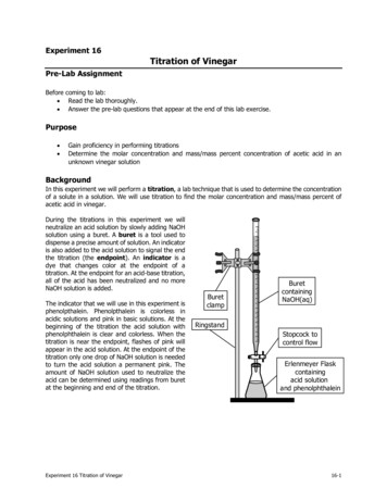
Experiment # 4(UNIVERSAL TESTING MACHINE- TENSILE TEST)Object: To compare various mechanical properties of a ductile material with a brittle material using tensile test onUniversal Testing Machine.Apparatus: 1) Universal Testing Machine (Instron 30kN)2) Flat Steel Specimen3) Flat Acrylic Specimen?Theory: The Universal Testing Machine is intended for static mechanical tests. Loading is done byhydraulic mechanism. Various tests can be performed on this machine using proper fixtures andattachments. One can perform tension test, compression test and bending tests on universaltesting machine. To obtain the stress-strain diagram of a material one usually conducts a tensiletest on a specimen of the material. ?Material: Specimen Type Round type / Flat type / Plate type. Alloy Steel. Polymer PMMA (Acrylic).Tensile Testing SetupMechanics of Materials Lab (ME-213)Tensile Testing GripsPage 1
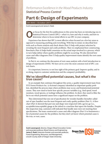
(a)(b)Various types of jawsa) Fish scale jaw.b) Saw tooth jaw.Various types of tensile testing specimenProcedure: The Materials Testing Machine is operated with a PC for all three types of test. Press the ON button to switch the drive on. The material testing machine can be driven with the controlbuttons. The selected and active buttons indicate this state with illuminated or blinking buttonlamps. The controls button includes the STOP , POS and TEST buttons. The materialtesting machine can be operated as an independent materials testing machine with integratedmachine. However a PC can be connected at any time for its controlling and monitoring. Thetesting machine must be at Pre-load before clamping the extensometer on specimen. In tensiontest, we use two types of special interchangeable jaws for gripping the specimen. The jaws mustbe fixed in pairs.1) Fish Scale for flat tensile specimen.2) Saw tooth (small) for round tensile specimen.3) Saw tooth (large) for round tensile specimen.After the fixing of jaws, clamp the specimen between the jaws and set the minimum distancebetween the specimen grips. After clamping the specimen, fix the extensometer. Then set thetesting parameters via PC and start the test. During the tension test, an elongation is observedinitially and afterwards the specimen ruptures. The graph is plotted automatically on an externalPC. The broken specimen can be taken out by unclamping the jaws. Now repeat the sameprocedure for other tensile specimen and observe the results on external PC.Mechanics of Materials Lab (ME-213)Page 2
Results & Graphs: - (For steel and PMMA provided through excel sheet)Discussion: - ?Conclusion: -?Abstract: -?References / Bibliography: -?QuestionsQ1 What is ‘Static testing’? Give some examples?Q2 What is ‘Strain Hardening’ and in which direction, the load is applied in the test?Q3 Why the Zwick and Instron testing machine is called ‘Universal Testing Machine’?Q4 Is high and low temperature test possible on Instron UTM. If yes, what’s their temperature range?Q5 Enlist the mechanical properties which is evaluated in the tension test?Q6 PMMA stands for and enlist their mechanical properties?Q7 What is the purpose of load cell and why tension test only be performed on ductile materials?Q8 Explain the purpose of using extensometer during the tension test?Q9 What does the material show if it has high percent elongation?Q10 Is there any difference between resilience and toughness? Elaborate with graph?Q11 An alloy specimen having a diameter of 12.8 mm and a gage length of 50 mm was tested tofracture. Load and deformation data obtained during the test are given below. Plot the Stress-Straindiagram on MS-Excel and determine the following on the graph and also show calculations?a.b.c.d.e.Modulus of Elasticity.The Proportional Limit.The Ultimate Strength.The Fracture Stress.The Modulus of Resilience.Load (kN)Change in Length 041.001.00Mechanics of Materials Lab (ME-213)Load 7.9045.10—Change in Length ure—Page 3
EXERCISE 4AA bronze alloy specimen having a diameter of 12.8 mm and a 50 mm gage length was tested tofracture. Stress and Strain data obtained during the test are shown in the figure below. Determinethe following parameters with units?Solution: a. Modulus of Elasticity b. The Proportional Limit c. The Ultimate Strength d. The yield strength (at 0.2% offset) e. The Fracture Stress f. Modulus of Resilience g. The true fracture stress if the final diameter of the specimen at the fracture location was10.5 mm Mechanics of Materials Lab (ME-213)Page 4
EXERCISE 4BLabel the following Stress strain diagram for Alloy steel from the following pool /glossary and fillappropriately in the table below.Plastic behavior, Elastic behavior, Yielding region, Necking region, Strain hardening region, Elasticregion, Plastic region, Yield stress, Proportional limit, Ultimate stress, Elastic limit, Fracture stress.CFBDBBEBBBBBAGBHBKBA B C D E F Mechanics of Materials Lab (ME-213)IJBBLBG H I J K L Page 5
Experiment # 3 & 4(UNIVERSAL HARDNESS TESTING MACHINE)Object: - To determine the Hardness of the given specimen through:a) Rockwell’s Hardness Test.b) Brinell’s Hardness Test.c) Vicker’s Hardness Test.Apparatus: - ?1)2)3)4)5)6)7)8)Universal Hardness Testing Machine.Various specimens. (Steel, Aluminium, Brass)Diamond Indenter. (for Rockwell Test)1/16” ball indenter. (for Rockwell Test)1 mm ball indenter. (for Brinell test)2.5 mm ball indenter. (for Brinell test)Diamond pyramid Indenter. (for Vickers Test)L.N key. (for changing of indenters)?Mechanics of Materials Lab (ME-213)Page 1
Theory: Hardness can be defined as a measure of a material’s resistance to localized plasticdeformation. (i.e. small dent or a scratch). Hardness tests are performed more frequently thanany other mechanical test for several reasons.1) They are simple and inexpensive. i.e. no special specimen need to be prepared.2) The test is non-destructive i.e. the specimen is neither fractured nor excessivelydeformed and a small indentation is the only deformation.3) Other mechanical properties often may be estimated from the hardness data.The following are the most common hardness testing techniques. Rockwell Hardness Tests. Brinell Hardness Tests. Vickers Hardness Tests. Knoop Hardness Tests.Rockwell Hardness Tests: It is the easiest among all hardness tests. This test constitute the most common method usedto measure hardness because they are so simple to perform and requires no special skills.Several different scales may be utilized from possible combinations of various indenters anddifferent loads, which permit the testing of virtually all metal alloys and some of thepolymers. The indenters include spherical tungsten carbide balls as well as a conical diamondindenter, which is used for the hardest materials. With this system, a hardness numberdesignated by HR is determined by the difference in depth of penetration resulting from theapplication of an initial minor load followed by a large major load. The utilization of minorload enhances test accuracy. The minor load is 10 kg, whereas major loads are 60, 100 and150 kg respectively. ?Brinell Hardness Test: In this test, a hard spherical indenter is forced into the surface of the metal(specimen) to betested. The material of the indenter is hardened steel whose diameter is 10 mm. The standardload range is between 500 and 3000 kg in 500 kg increments. During a test, the load ismaintained between 10 to 30 sec. However harder materials require greater application ofloads. The hardness obtained through this test is called Brinell Hardness Number (BHN) andis designated by HB. ?Vickers Hardness Test: It is also called ‘diamond pyramid’ test. In this test, a very small diamond indenter havingpyramidal geometry is forced into the surface of the specimen. The applied loads are muchsmaller as compare to Rockwell and Brinell tests. The ranging is in between 1 and 1000 g.Mechanics of Materials Lab (ME-213)Page 2
The resulting impression is observed under a microscope and measured. Then thismeasurement is converted into a hardness number which is designated by HV. This type oftest is well suited for measuring the hardness of small, selected specimen regions. Carefulspecimen surface preparation is necessary in order to ensure a well-defined indentation thatnay be accurately measured.There is another technique of hardness test, known as ‘Knoop Hardness Test’. The testingcriteria and the hardness scale are approximately equivalent to Vickers’s test. However,Knoop’s technique is used for testing brittle materials such as ceramics. ?Load Selection: S NoType of Test1Rockwell2Brinell3VickersLoad & Type of Indenter60, 100 & 150 kgf with ball and diamond coneindenters.5, 10 & 30 kgf with 1 mm diameter ball indenter62.5 & 187.5 kgf with 2.5 mm ball indenter.3, 5, 10, 30 & 100 kgf.IndenterMechanics of Materials Lab (ME-213)Page 3
Various Indenter TypesLoad SelectorsMechanics of Materials Lab (ME-213)Page 4
Procedure: Rockwell Hardness Tests: 1)2)3)4)5)6)7)8)9)Fix the indenter into the moveable sleeve with the help of L.N key.Place the specimen onto the sample holder.Select the load at which the test will perform.The preload is applied by bringing the specimen into contact with the indenter byturning the hand wheel clockwise.The movement of the indenter is displayed by a bar graph and the correct pre-loadposition is indicated when the horizontal bar touches the end of the fixed bar.When the point is reached, an audible beep will be heard and the vertical movementof the indenter should be stopped.The rest of the loading cycle is automatic. The application and removal of theadditional load again displayed by the bar graph.At the end of the load cycle, record the hardness number which will be displayed.Now change the indenter and repeat the procedure for different specimen. Reference Text Book Fundamentals of Materials Science and Engineering by William D Callister.Brinell Hardness Test: 1) For performing Brinell hardness test, two type of indenters are available for thehardness tester i.e. 1” ball and 2.5” ball indenters.2) Fix the indenter into the moveable sleeve with the help of L.N key.3) Place the specimen onto the sample holder.4) Set the Brinell test from the display panel and select the load at which the test willperform.5) Now having focused the test surface and selected the test area advance the indenter toits forward position and initiate the load cycle by pressing the „S‟ key.Mechanics of Materials Lab (ME-213)Page 5
6) A bar graph will now appear on the screen which indicates the downward movementof the indenter carrier and the audible signals will signal the following critical testevents.7) The first signal will indicate the application of the test load and a countdown inseconds of the full load dwell period will appear.8) There will be a further signal that will indicate the end of the test load dwell time.9) At the end of the loading cycle, d1 will appear on the display to prompt measurementof the impression.10) A circular impression has been formed that we can see from the eye piece ofmicroscope.11) Since there are two knurled knobs on the measuring eye piece, the right-hand knobmoves both lines simultaneously, and this should be adjusted first until the left handline just touches the left hand corner of the diagonal. The left-hand knob adjust theright hand line independently and this again should be adjusted until the line touchesthe right hand corner of the impression.12) There are two types of lines which can be seen on the specimen through the eye piece.Now adjust the right hand line and then adjust left hand line.13) With both lines touching the impression corner, load the data by pressing the pushbutton and live reading of d1 will be appeared on the screen.14) Now rotate the microscope and repeat for the vertical diagonal if necessary, otherwiseload the first reading a second time, to complete the measurement.15) The hardness number and scale will be appeared on the screen. Note the reading.Vickers Hardness Test: 1) For performing Vickers hardness test, diamond indenters are used.2) The procedure is similar to the Brinell hardness test except that a pyramid typeimpression has been formed that we can see from the eye piece of microscope.3) The procedure for measuring d1 and d2 is also similar to the Brinell hardness test.Mechanics of Materials Lab (ME-213)Page 6
Reference Text Book Fundamentals of Materials Science And Engineering by William D Callister.Mechanics of Materials Lab (ME-213)Page 7
Results: 1) Rockwell Test: S#Type of IndenterMaterialLoad Graph: - (Between Load and Hardness)Mechanics of Materials Lab (ME-213)Page 8
2) Brinell Test: S#Type rdness.1.2.3.4.5.6.Graph: - (Between Load and Hardness)Calculations: - *(Perform the sample calculations)Mechanics of Materials Lab (ME-213)Page 9
3) Vickers Test: Type eticalHardness.1.2.3.4.5.6.Graph: - (Between Load and Hardness)Calculations: - *(Perform the sample calculations)Discussion: - ?Conclusion: - (Compare the results obtained in the lab with the results obtained by relevant formulae). Rockwell Test. ?Brinell Test. ?Vickers Test. ?Abstract: - ?References / Bibliography: - ?Mechanics of Materials Lab (ME-213)Page 10
QuestionsQ1 Why hardness test are performed more often than any other mechanical tests?Q2 Why the hardness testing machine is called ‘Universal Hardness Testing Machine’?Q3 Should brittle materials possesses larger hardness number? Give reasons to your answer?Q4 If the specimen material is softer, what will be the effect of its hardness?Q5 What does the Rockwell Hardness scale shows. Explain its importance and significance?Q6 What is the relation between hardness and stiffness? Show with graphs?Q7 Which type of hardness test is performed on polymers?Q8 What is Indenter? Briefly describe various type of indenters?Q9 What do we understand by the term „dwell time‟?Q10 How many types of load selector present in Hardness Tester. Name and explain thepurpose of each type of load selector?Q11 Illustrate the purpose of pressing “S” key during the hardness tests?Q12 What is the effect on hardness of material when the applied load is increased? (Discussall three hardness test results)Q13 How can a Brinell hardness number for steel alloys can be converted into its tensilestrength?Q14 Which type of impression is formed in Vickers hardness test?Q15 Enlist the factors if there are difference in results obtained in the experiment and byrelevant nics of Materials Lab (ME-213)Page 11
Experiment # 8FATIGUE TESTING MACHINEObject: a) To draw the S-N diagram by with the help of fatigue test.b) To study the effect of various curvature radii and surface qualities on fatigue.Theory: When a metal is subjected to repeat cycles of stress or strain, it causes its structure tobreakdown ultimately leading to fracture. This behaviour is called fatigue. Fatigue failure iscatastrophic which means that it happens suddenly. It is generally responsible for a largepercentage of failures in various mechanical and automotive components. Fatigue is a form offailure that occurs in structures subjected to dynamic and fluctuating loads. Under thesecircumstances, it is possible for failure to occur at a stress level considerably lower than theyield strength for a static load. It generally occurs after a lengthy period of repeated stress orstrain cycling.The process of fatigue failure is characterized by three specifics steps.a) Crack initiation.b) Crack propagation.c) Final failure.Wohler Machine1.2.3.4.5.6.7.8.Proximity sensor.Spindle with specimen receptacle.Floating Bearing.Scale.Spring Balance.Hand Wheel.Proximity Switch.Protective Hood.Mechanics of Materials Lab (ME-213)Page 1
9. Drive Motor.10. Emergency off switch.11. Counter.12. Connection socket. (optional)13. Motor Protection switch.Wohler in 1871 was the first to introduce the concept of the so-called S-N diagram. That whythis machine is called Wohler machine. In the moving fatigue testing machine, a rotatingspecimen is clamped on one side is loaded with a concentrated force. As a result analternating bending stress is created in the cylindrical specimen. Following a certain numberof load cycles, the specimen will rupture as a result of material fatigue. With this machine, itis possible to demonstrate the basic principles of fatigue strength testing, including theproduction Stress-No. of cycles diagram (S-N diagram). The specimen is subjected to a purereversed bending stress in the machine. With different specimen shapes, it is possible to showthe influence of the notch effect and the influence of surface quality on fatigue strength. ?Specimen Material C35E (Alloy of Cr Mo Ni)Procedure: - Part (a)1) First of all fold up the protective hood.2) Relieve the load device using the hand wheel by moving the floating bearing down tothe bottom. Remove any specimens which may be in position.3) Lightly tighten the union nut on the collets chuck.4) Fold down the protective hood and loosen the emergency off switch.5) Reset the counter using the RST button. The counter must display zero.6) After checking all these parameters, the experiment can begin.7) Make sure that the floating bearing must be at the height of the spindle.8) Insert the test bar in the floating bearing of the load device.9) Afterwards insert the test bar in the collate chuck and push in as far as the end stopand carefully tighten the collets chuck using a wrench.10) Now check the concentricity of the specimen by rotating the spindle by hand and folddown the protective hood. (Remember the unit can only be placed in operation if the protectivehood is correctly closed)11) Loosen the emergency off switch and quickly apply the load by rotating the handwheel.12) Read off the load from the scale on the spring balance.13) Reset the counter using the RST button in order to begin counting.14) The motor stops automatically when the specimen ruptures. Read off the number ofload cycles from the counter and record it in the observation table.15) Repeat the experiment for the next specimen.16) The stresses are entered over the endurance in the semi-logarithmic diagram i.e. theattached worksheet and draw the graph between stress and no. of cycles. This graph iscalled S-N diagram.Mechanics of Materials Lab (ME-213)Page 2
Procedure: - (Part b)The procedure is similar to the previous test except that you need to switch off themotor after completion of the required number of cycles.Results: a) Number of load cycles for test bar under different loadsNo.12345Load (N)200170150130120Stress σ (N/mm2)400340300260240Endurance (n)14130489001680004560001281800Duration (min)51760162457b) The Influence of Various Curvature Radii and Surface Qualities:Test bar # 1 Small radius and smooth.Test bar # 2 Large radius and smooth.Test bar # 3 Large radius and rough.The following numbers of load cycles are achieved until the specimen ruptures.No.123Load ( F)Stress (σa)200 N400 N/mm2Specimen 111.40017.18014.060Specimen 211.40017.36012.920Specimen 311.80023.90016.600Average11.53319.48014.526Number of load cycles N ( 200) to rupture.Drawing: -? (Using AutoCAD or any CAD software)Discussion:- ?Conclusion: - ?With an identical curvature radius, the specimen with the smoother surface (i.e. test bar # 2)has a higher endurance than the one with the rougher surface (i.e. test bar # 3).(More elaboration is required)?Abstract: - ?References / Bibliography: - ?Mechanics of Materials Lab (ME-213)Page 3
Specimen DrawingsS-N DiagramQuestionsQ1 What do you understand by the term “Fatigue strength”?Q2 How many types of fatigue exists? Name them?Q3 Fatigue failure is „catastrophic‟. What does it mean?Q4 What is ‘Endurance’? Is there any difference between endurance and # of cycles?Q5 Explain the process of crack initiation in fatigue?Q6 How does the cracks propagate in the specimen that leads to its final failure?Q7 Enlist the factors that affect the fatigue life of specimen?Q8 How can the fatigue life and surface hardness of steel alloys can be upgraded?Q9 What is „thermal fatigue‟? Does this experiment belong to it?Q10 What is the effect on the fatigue life of specimen having good surface finish hanics of Materials Lab (ME-213)Page 4
Experiment # 7TORSION TESTING APPARATUSObject: To investigate the relationship between torque and twist for various circular cross sectionsspecimen.Apparatus: - ? (Take help from figures)Theory: The elastic deflection and eventual failure of beams in bending is related to the behaviour ofthe beam material in direct tension and compression. However there is another way ofdistorting material that occurs when it is twisted. As a simple case, a length of round rod canbe twisted about its longitudinal axis in such a way that no bending or direct stress isinvolved. This is called pure torsion.ORTorsion is one of the common modes of deformation in which a solid or tubular member issubjected to torque about its longitudinal axis resulting in twisting deformation. Torsion ofshaft is very common in mechanical engineering where power transmission takes place. ?Angle of Twist, θ TL/GJWhere T Torque. (N-mm)L Length of rod. (mm)G Modulus of Rigidity of material. (N/mm2)J π / 32 d4 Polar Moment of Inertia. (mm4)d diameter of rod. (mm)Mechanics of Materials Lab (ME-213)Page 1
Procedure: 1) Measure and record the diameter of aluminium rod.2) Fit the round aluminium specimen into the chuck on the torsion head and in the chuckfitted to the vertical pier whose function is to hold the end of the torsion specimen.3) The chuck in the vertical pier has a through hole right through it and the pie, thus allowingthe test specimen length to be fully adjustable.4) Then the torsion specimens are secured within the chucks by using the chuck key.5) Rotate the chuck keys within the chucks bring the chuck jaws around the specimens andlock them into position.6) After clamping specimen in position, put the load hanger on the cord.7) Now set the pointer to be 400 mm from the vertical pier with integral chuck and bring theprotractor block close to the pointer and zero the pointer.8) Afterwards add a load from 5N to 15N in 5N increments and record the twist of thespecimen for each increment in table # 7(a).9) Remove the load, move the rotation angle and pointer to 200 mm from the clamp andrepeat the above procedure.10)
Mechanics of Materials Lab (ME-213) Page 1 Experiment # 4 (UNIVERSAL TESTING MACHINE- TENSILE TEST) Object: - To compare various mechanical properties of a ductile material with a brittle material using tensile test on Universal Testing Machine. Apparatus: - 1) Universal Testing Machine (Instron 30kN) 2) Flat Steel Specimen