Transcription
Instruction Manualibidi Heating System, Universal FitVersion 2.2Lid Plate0I 42.1 37.0S[ 42.0] 37.N.C. RunGlassN.C.37.0Setup10918 ibidi Heating System, Universal Fit for 1 Chamber
ibidi Heating System, Universal FitVersion 2.2 (May 23, 2019)2Instruction Manual
ibidi Heating System, Universal FitContactibidi GmbHLochhamer Schlag 1182166 GräfelfingGermanyPhone: 49 89 / 520 46 17 - 0Fax: 49 89 / 520 46 17 - 59E-mail: info@ibidi.deInternet: ibidi.comInstruction Manual3Version 2.2 (May 23, 2019)
ibidi Heating System, Universal FitContents1Preamble61.1Introduction . . . . . . . . . . . . . . . . . . . . . . . . . . . . . . . . . . . . . . . . . . .61.2Safety Symbols . . . . . . . . . . . . . . . . . . . . . . . . . . . . . . . . . . . . . . . . .61.3Nomenclature . . . . . . . . . . . . . . . . . . . . . . . . . . . . . . . . . . . . . . . . . .71.4Specifications . . . . . . . . . . . . . . . . . . . . . . . . . . . . . . . . . . . . . . . . . .71.5Disclaimer . . . . . . . . . . . . . . . . . . . . . . . . . . . . . . . . . . . . . . . . . . . .101.6Safety Considerations . . . . . . . . . . . . . . . . . . . . . . . . . . . . . . . . . . . . . .101.7Regulatory Statement . . . . . . . . . . . . . . . . . . . . . . . . . . . . . . . . . . . . . .111.8Limited Warranty . . . . . . . . . . . . . . . . . . . . . . . . . . . . . . . . . . . . . . . .121.9Transporting the ibidi Heating System, Universal Fit . . . . . . . . . . . . . . . . . . . .121.10 Repairing the ibidi Heating System, Universal Fit . . . . . . . . . . . . . . . . . . . . .131.11 Waste Disposal – WEEE/RoHS Compliance Statement . . . . . . . . . . . . . . . . . .131.11.1 EU Directive WEEE . . . . . . . . . . . . . . . . . . . . . . . . . . . . . . . . . . .131.11.2 EU Directive RoHS . . . . . . . . . . . . . . . . . . . . . . . . . . . . . . . . . . .132Intended Use143Principle144Equipment154.1Components of the ibidi Heating System, Universal Fit . . . . . . . . . . . . . . . . . .154.2Combination Options . . . . . . . . . . . . . . . . . . . . . . . . . . . . . . . . . . . . . .164.3Temperature Controller . . . . . . . . . . . . . . . . . . . . . . . . . . . . . . . . . . . . .174.4Heated Lid . . . . . . . . . . . . . . . . . . . . . . . . . . . . . . . . . . . . . . . . . . . .184.5Heated Plate . . . . . . . . . . . . . . . . . . . . . . . . . . . . . . . . . . . . . . . . . . .194.6Heating Inserts . . . . . . . . . . . . . . . . . . . . . . . . . . . . . . . . . . . . . . . . .204.6.1Heating Insert µ–Slide . . . . . . . . . . . . . . . . . . . . . . . . . . . . . . . . .204.6.2Heating Insert µ–Dish 35mm, high and Heating Insert µ–Dish 35mm, low . . . . . .20Version 2.2 (May 23, 2019)4Instruction Manual
ibidi Heating System, Universal Fit5Operation225.1Installation and Connection of the Parts . . . . . . . . . . . . . . . . . . . . . . . . . . .225.2Start the ibidi Heating System, Universal Fit . . . . . . . . . . . . . . . . . . . . . . . .235.3Setting Parameters in the Front Display . . . . . . . . . . . . . . . . . . . . . . . . . . .235.3.1Run/Stop Mode . . . . . . . . . . . . . . . . . . . . . . . . . . . . . . . . . . . .245.3.2Incubation Parameters . . . . . . . . . . . . . . . . . . . . . . . . . . . . . . . . .245.3.3Setup Menu . . . . . . . . . . . . . . . . . . . . . . . . . . . . . . . . . . . . . . .245.4Temperature Adjustment in the Sample . . . . . . . . . . . . . . . . . . . . . . . . . . .265.5Sample Preparation . . . . . . . . . . . . . . . . . . . . . . . . . . . . . . . . . . . . . . .276IncuControl Software287Maintenance297.1Disinfection and Cleaning . . . . . . . . . . . . . . . . . . . . . . . . . . . . . . . . . . .297.2Influence of Ambient Temperature and Ventilation . . . . . . . . . . . . . . . . . . . . .298Troubleshooting308.1Focus not Stable . . . . . . . . . . . . . . . . . . . . . . . . . . . . . . . . . . . . . . . . .308.2Evaporation Is too High . . . . . . . . . . . . . . . . . . . . . . . . . . . . . . . . . . . .308.3Condensation Inside the Stage Top Incubator . . . . . . . . . . . . . . . . . . . . . . . .30Instruction Manual5Version 2.2 (May 23, 2019)
ibidi Heating System, Universal Fit11.1PreambleIntroductionThis manual is your guide to using the ibidi Heating System, Universal Fit for cell culture experiments on an optical microscope. It instructs first-time users how to use the instrument, and serves asa reference for experienced users.Before using the ibidi Heating System, Universal Fit, please read this instruction manual carefullyand make sure that the contents are fully understood. This manual should be easily accessible to theoperator at all times during instrument operation. If this manual gets lost, order a replacement fromwww.ibidi.com.To ensure safe operation, the ibidi Heating System, Universal Fit must only be operated with thesupplied components and according to the instruction manual.1.2Safety SymbolsNote that the signal words WARNING, CAUTION and NOTE have specific meanings in this manual. Do not proceed beyond a signal word until you have performed the indicated actions.WARNING!A potentially hazardous situation which, if not avoided, could result in serious injury or even death. Warning messages in the text are displayed in agray shaded box.CAUTIONA potentially hazardous situation which, if not avoided, could result in minoror moderate injury. It is also used to alert against damaging the equipmentor the instrument.NOTEAdditional information to help achieve optimal instrument and assay performance.Symbols on the product identification label and back panel of the device:CE Marking: This symbol indicates the product’s compliance with EU legislation.This label is positioned on the back of the device and prompts you to read themanual before using the device.Product disposal: The symbol indicates that this product must be recycled/disposed of separately from other household waste. See page 13 fordetails.Version 2.2 (May 23, 2019)6Instruction Manual
ibidi Heating System, Universal Fit1.3NomenclatureTemperature Controller1.4Heated LidHeated PlateSpecificationsOnly operate the Heating System in the range of the specifications given below:Table 1 – Specifications of the ibidi Heating System, Universal FitElectrical Specifications Power SupplyProtection classInternational protection marking(IEC 60529)Overvoltage categoryExternal power supplyInput line voltage TemperatureControllerOutput voltage to channel 1(Heated Lid), Universal FitOutput voltage to channel 2(Heated Plate), Universal Fit, for 1ChamberIIP 20IIAC 100-240 V, 50/60 Hz, 2 ADC 24 V, 6.67 A, 160 WDC 10 V, max. 5 ADC 12 V, max. 5 AOperating and Storage ConditionsOperating siteOperating temperatureOperating humidityOperating altitudeStorage conditionsIndoor use only18-30 C/64-86 F (min 5 C/9 F less than set temperature)max. 80% relative humidity (RH)max. 2000 m (atmospheric pressure 800-1060 hPa/11.6-15.4psi)-5-50 C/23-122 F, humidity 60% relative humidity (RH)Outer Dimensions and Characteristics of the ComponentsTemperature ControllerHeated LidInstruction Manual90 mm 170 mm 230 mmWeight: 1720 g/3.8 lbs19 mm 85.5 mm 127.5 mm (134.5 mm with cover ridge)Length of cable: 1.5 m7Version 2.2 (May 23, 2019)
ibidi Heating System, Universal FitTable 1 – (continued)Heated PlateHeated PlateHeated LidassembledwithHeating Inserts allHeating Insert 35 mm Dish highHeating Insert 35 mm Dish lowHeating Insert SlidesUSB cablePower supply cableConnector to Gas Incubation: Female Luer Lock12 mm 85.5 mm 127.5 mmObservation area: 40 mm 82 mmLength of cable: 1.5 mHeight: 25.5 mmWeight: 330 g/0.46 lbs47 mm 97 mmHeight without blank holder: 8 mmHeight with blank holder: 16-18 mmObservation area: 22 mmWeight insert: 50 g/0.11 lbsWeight blank holder: 72 g/0.16 lbsHeight without blank holder: 8 mmHeight with blank holder: 13-15 mmObservation area: 22 mmWeight insert: 50 g/0.11 lbsWeight blank holder: 47 g/0.11 lbsHeight without blank holder: 8 mmHeight with blank holder: 13-15 mmObservation area: 49 mm 22 mmWeight insert: 42.5 g/0.94 lbsWeight blank holder: 38.5 g/0.85 lbsLength: 1.8 mLength: 2.0 m (power supply to wall)Length: 1.2 m (power supply to device)Temperature Control RangeHeated LidHeated PlateAmbient temperature (min. 18 C) to 45 CAccuracy: 0.2 C (at sensor location) 5 C (entire heated glass)Ambient temperature (min. 18 C) to 45 CAccuracy: 0.2 C (at sensor location) 0.5 C (entire heated plate)Recommended Temperatures before AdjustmentSee Section 5.4USB InterfaceConnector typeRecommended USB cableDriverVersion 2.2 (May 23, 2019)USB 2.0 Connector Type BTripp Lite UR022-006 (shielded)FTDI VCP driver8Instruction Manual
ibidi Heating System, Universal FitTable 1 – (continued)Microscope RequirementsWorking distance condenserStage holder 26 mmHolder for standard multi-well platesOptical Properties Glass LidGlassThickness of the glass plateRefractive index glassITO coatingPassivation layerRefractive index ITO with passivation layerInstruction ManualSelected HQ Floatglass1.1 mmnD 1.520 (588 nm)Thickness: 100 nmThickness: 20-25 nm1.959Version 2.2 (May 23, 2019)
ibidi Heating System, Universal Fit1.5Disclaimer ibidi shall not be held liable, either directly or indirectly, for any damage incurred as a result ofproduct use. The contents of this manual are subject to change without notice for product improvement. This manual is considered complete and accurate at publication. This manual does not guarantee the validity of any patent rights or other rights. If an ibidi software program doesn’t function properly, this may be caused by a conflict fromanother program operating on the computer. In this case, take corrective action by uninstallingthe conflicting product(s). ibidi is a registered trademark of ibidi GmbH in Germany and other countries.1.6Safety ConsiderationsWARNING! Only operate the ibidi Heating System, Universal Fit with the supplied components. Only use the cables and plugs delivered with the system. The power plug of the control unitmust be inserted in an outlet with a ground (earth) contact. Do not replace detachable power cables by power cables with inadequate specifications. Byviolating these instructions you risk electric shock and fire. Only use extension cables that have a protective ground wire. Do not operate the ibidi Heating System, Universal Fit under conditions that pose a risk ofexplosion, implosion, or the release of gases. Only operate the ibidi Heating System, UniversalFit with aqueous solutions. Do not operate a damaged ibidi Heating System, Universal Fit. If the housing seems damagedor something is rattling inside the controller, contact the ibidi service hotline for repair. Some accessible parts of the Heated Plate and Heated Lid can reach temperatures up to 55 C.Avoid touching the temperature-controlled parts of the system when you have set the Temperature Controller to high temperatures.CAUTION Ensure that the external power supply is easily accessible. The ibidi Heating System, UniversalFit must be installed in a manner such that none of its components hinders access to the externalpower supply. Immediately replace damaged cords, plugs, or cables to avoid risk of personal injury or damageto the instrument.Version 2.2 (May 23, 2019)10Instruction Manual
ibidi Heating System, Universal Fit Only ibidi technical staff and technical staff instructed by ibidi are permitted to open and service the ibidi Heating System, Universal Fit. The external power supply should not be brought into contact with moisture. If the housing isdamaged, the external power supply should not be used. Avoid strong magnetic fields and sources of high frequency. The ibidi Heating System, Universal Fit might not function properly when located near a strong magnetic field or high frequencysource. Avoid vibrations from vacuum pumps, centrifuges, electric motors, processing equipment, andmachine tools. Avoid dust and corrosive gas. Do not install the ibidi Heating System, Universal Fit where itcould be exposed to high levels of dust or to outside air or ventilation outlets. Install the ibidi Heating System, Universal Fit in a horizontal and stable position, such as atable, bench, or desk upon which the instrument is installed. Install the ibidi Heating System, Universal Fit in a location that enables easy access for maintenance. Do not place heavy objects on the instrument. The heated glass plates of the incubation chamber can break on mechanical impact. If so, theglass shards can lead to injuries if handled. Be aware that when switched on, a 10 V DC voltage is applied to the underside of the glass onthe Heated Lid. Do not touch the underside or put it in contact with anything conductive. Thiscould cause a short circuit that may damage the Temperature Controller and/or the HeatingDevices.1.7Regulatory StatementThe ibidi Heating System, Universal Fit has been designed, produced and tested in compliance withthe European standard DIN EN 61010-1 (IEC 61010-1, ”Safety requirements for electrical equipmentfor measurement, control and laboratory use”). Furthermore it meets the IEC 61326-1 (”Electricalequipment for measurement, control and laboratory use - EMC requirements”) and CISPR 11 (”International Standard for electromagnetic emissions (disturbances) from Industrial, Scientific and Medical (ISM) Equipment”) standards .The device carries the CE mark.The ibidi Heating System, Universal Fit meets the Low Voltage Directive 2014/35/EU and theEMC Directive 2014/30/EC.Instruction Manual11Version 2.2 (May 23, 2019)
ibidi Heating System, Universal Fit1.8Limited WarrantyProducts manufactured by ibidi, unless otherwise specified, are warrantied for a period of one yearfrom the date of shipment to be free of defects in materials and workmanship. If any defects in theproduct are found during this warranty period, ibidi will repair or replace the defective part(s) orproduct free of charge.This warranty does not apply to defects resulting from the following:1. Improper or inadequate installation.2. Improper or inadequate operation, maintenance, adjustment, or calibration.3. Unauthorized modification or misuse.4. Use of unauthorized tubing or fluidic connectors.5. Use of consumables, disposables, and parts not supplied by an authorized ibidi distributor.6. Corrosion due to the use of improper solvents, samples, or due to surrounding gases.7. Accidents beyond ibidi’s control, including natural disasters.This warranty does not cover consumables, such as cell culture chambers and dishes, tubes, fluidicconnectors, reagents etc.The warranty for all parts supplied and repairs provided under this warranty expires on the warrantyexpiration date of the original product.1.9Transporting the ibidi Heating System, Universal FitThe weight of the Temperature Controller is approx. 1.7 kg/3.8 lbs. Moving the Temperature Controller during operation can pose a risk of personal injury or damage to the instrument.For transport, switch off the Temperature Controller and then disconnect the heated componentsfrom the controller. Carry the devices carefully and avoid mechanical shocks.WARNING!Hot surface (max. 55 C)! Do not touch Heated Lid and Heated Plate when hot. Always disconnectthe instrument from the power supply before transport and leave the instrument to cool downfor approx. 5 minutes.Version 2.2 (May 23, 2019)12Instruction Manual
ibidi Heating System, Universal Fit1.10Repairing the ibidi Heating System, Universal FitFor inquiries concerning repair service, contact the ibidi service personnel and provide the modelname and serial number of your system.ibidi GmbHService Hotline: service@ibidi.comCAUTIONDo not try to repair the ibidi Heating System, Universal Fit by yourself. Disassembly of the ibidiHeating System, Universal Fit is not allowed. Disassembly poses a risk of personal injury ordamage to the devices. Contact ibidi service personnel if there is a need to disassemble a device.1.11Waste Disposal – WEEE/RoHS Compliance StatementThe European Union (EU) has enacted two directives, the first on product recycling (Waste Electricaland Electronic Equipment, WEEE) and the second on limiting the use of certain substances (Restriction on the use of Hazardous Substances, RoHS).1.11.1EU Directive WEEEThe ibidi Heating System, Universal Fit must be disposed of in compliance with the WEEE Directive2012/19/EC.This symbol on the product is in accordance with the European Union’s Waste Electrical and Electronic Equipment (WEEE) Directive. The symbol indicates that this product must be recycled/disposed of separately from other household waste. It is the end user’s responsibility to dispose of thisproduct by taking it to a designated WEEE collection facility for the proper collection and recycling ofthe waste equipment. The separate collection and recycling of waste equipment will help to conservenatural resources and protect human health and the environment. For more information about recycling, please contact your local environmental office, an electrical/electronic waste disposal companyor distributor where you purchased the product.1.11.2EU Directive RoHSThe ibidi Heating System, Universal Fit meets the requirements set forth in the RoHS Directive2011/65/EU and the additional terms as specified in RoHS Directive 2015/863/EU.Instruction Manual13Version 2.2 (May 23, 2019)
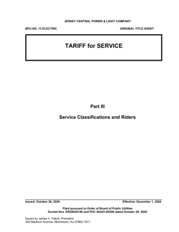
ibidi Heating System, Universal Fit2Intended UseThe ibidi Heating System, Universal Fit is a stage top incubator for live cell imaging that fits ontoinverted microscope stages with a universal mounting frame for multiwell plates. The geometry ofthe chamber, with a heated glass plate above the sample, provides a platform for keeping microscopyslides and dishes at a constant temperature during an experiment on a microscope.For full control of the incubation environment, the ibidi Heating System, Universal Fit can be combined with the ibidi Gas Incubation System to regulate the CO2 and O2 concentrations as well as thehumidity.The modular concept of the Heating Inserts enables the use of a variety of microscopy labware ranging from 35 mm dishes to regular slides.3PrinciplePhysiological Conditions in Live Cell ImagingThe Heated Lid and Heated Plate are designed to keep cells on-stage at 37 C in microscopy slidesand dishes (Figure 1). To achieve this, the glass top of the Heated Lid and the Heated Plate areactively heated by the Temperature Controller. The Heated Lid prevents condensation effects insidethe incubation system (Figure 2).CO2 LevelsHumidityHeated LidHumidity SensorGas mixture,HumidityTemperatureCell culture vessel37 40 CO2 LevelsHeated PlateFigure 1 – Schematic cross-sectional view of the ibidi Heating System, Universal Fit.ibidi solution: Heated LidUnheated Lid34 C40 C37 C37 CHeated PlateHeated PlateFigure 2 – The Heated Lid prevents condensation effects on the lid of the cell culture vessel.Version 2.2 (May 23, 2019)14Instruction Manual
ibidi Heating System, Universal Fit4EquipmentThis section provides a brief overview over all parts of the ibidi Heating System, Universal Fit including a description of the characteristics.4.1Components of the ibidi Heating System, Universal FitThe components of the ibidi Heating System, Universal Fit are listed below.DescriptionDrawingTemperature ControllerHeated Lid with electrical cable and D-sub connector toconnect to the Temperature ControllerHeated Plate with electrical cable and D-sub connector toconnect to the Temperature ControllerHeating Insert µ–Dish 35mm, high *Heating Insert µ–Dish 35mm, low *Instruction Manual15Version 2.2 (May 23, 2019)
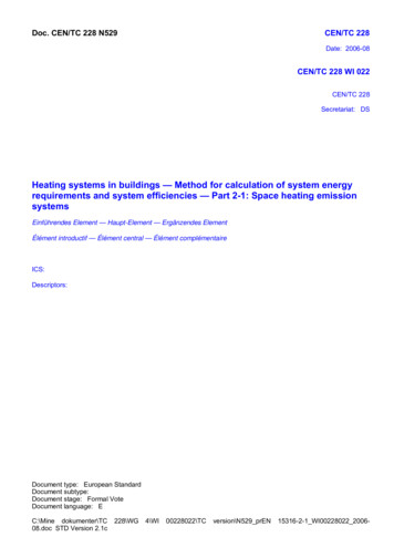
ibidi Heating System, Universal FitDescriptionDrawingHeating Insert µ–Slide*Heating Insert LabTek*Temperature Adjustment Set:1 temperature sensor1 perforated ibidi µ–Slide 8 Well1 perforated ibidi µ–Dish 35mm, high1 perforated ibidi µ–Dish 35mm, lowUSB cable to connect the Temperature Controller with acomputerCountry specific power cord to connect the external powersupply to the wall socketExternal power supply for the Temperature ControllerUSB flash drive with IncuControl software*One Heating Insert of your choice is delivered with the ibidi Heating System, Universal Fit. Ifneeded, more Heating Inserts can be ordered separately.4.2Combination OptionsThe parts of the ibidi Heating System, Universal Fit are combined as shown in Figure 3. The HeatedLid and Heated Plate fit on an inverted microscope stage equipped with a universal mounting framefor multiwell plates. They are connected to the Temperature Controller.The ibidi Heating System, Universal Fit can be combined with the Gas Mixer unit, that provides CO2and O2 (optional) control and a defined humidified atmosphere. Detailed information on the GasMixer unit is given in the Gas Mixer instructions.To hold several geometries of Slides and Dishes, the Heated Plate can be equipped with differentInserts (Section 4.6): Insert for µ–Dish 35mm, high , Insert for µ–Dish 35mm, low , Insert for µ–Slides, andInsert for LabTek chambered coverglass.For parallelization of experiments, the Heated Plate for 4 µ-Slides provides a platform to observe4 Slides in parallel. Detailed information is given in the instructions of the ibidi Heating System,Universal Fit for 4 µ-Slides (#10927).Version 2.2 (May 23, 2019)16Instruction Manual
ibidi Heating System, Universal FitFigure 3 – Overview of the parts of the ibidi Heating System, Universal Fit with options to combine4.3Temperature ControllerThe Temperature Controller is designed to control the different heated components (four channelsavailable).The front display shows the set values (S) and the current values (I). The settings can be adjusted viathe control buttons (Section 5.3).If you wish to control the Temperature Controller via PC, use the IncuControl software (Section 6).Instruction Manual17Version 2.2 (May 23, 2019)
ibidi Heating System, Universal FitFigure 4 – Front view of the Temperature Controller.The LEDs on the front indicate the status of the channels, connection to the power supply, and USBconnection (Figure 4).Control LEDs Channel 1-4LED offLED onLED fast blinkingChannel inactiveChannel activeChannel errorAll plugs for the electrical connections are integrated into the rear of the Temperature Controller(Figure 5). The setup of the connections is shown in Section 11.On/Off switchTem pSensoribidi GmbHAm Klopferspitz 19D-82152 MartinsriedGermany 49(0)89520 46 17 0www.ibidi.comType:ExternalthemperaturesensorCh 1ibidi Tem perature ControllerCh 2Ch 3Heated Plate, 4 SlidesHeated PlateUSBHeated Glass BottomProduction date:Heated LidUSBibidi Temperature ControlleribiTC2-00111/2018Serial number:Pow er24 Vm ax. 6.7 ACh 44 control channelsPower supplyFigure 5 – Rear view of the Temperature Controller.4.4Heated LidThe Heated Lid provides excellent optical quality, and also allows for the use of all standard microscopy techniques, including differential interference contrast (DIC). Due to the height of the lid,we recommend using condensers with a working distance of 26 mm.Version 2.2 (May 23, 2019)18Instruction Manual
ibidi Heating System, Universal FitThe upper glass part of the Heated Lid is heated. The electrical cable is connected to the TemperatureController. The Heated Lid fits exactly and securely onto the Heated Plate.For gas incubation, the Heated Lid is equipped with inlets for the gas flow and the humidity sensor.Detailed information on the Gas Incubation System is given in its instruction manual.Figure 6 – Heated Lid4.5Heated PlateThe Heated Plate provides the base for the ibidi Heating System, Universal Fit. The lower part of theHeated Plate fits into any microscope stage with a universal mounting frame for multiwell plates.The electrical cable (1.5 m) is connected to the Temperature Controller.Figure 7 – Heated Plate, top viewInstruction Manual19Version 2.2 (May 23, 2019)
ibidi Heating System, Universal Fit4.6Heating InsertsThe Heating Insert holds the sample and fits into the Heated Plate. The Insert is held in place bystrong neodymium magnets. Use the handles to place/remove the insert into/from the Plate of theibidi Heating System, Universal Fit.The Heating Inserts have a lower part (insert) that fit into the Heated Plate, and an upper part (holder)to press the sample down. The two–part inserts have two functions that both rely on the force of theintegrated magnets. The first function is to hold the Slides or Dishes firmly in position, so as to avoiddisplacement during microscope stage movements. The second is to create a tight contact betweenthe Slides or Dishes and the metallic insert, to maximize the heat transfer and ensure stable heatingof the sample. The Heated Plate passively heats the inserts.WARNING!Heated Plate, Heated Lid, and Heating Inserts all contain strong neodymium magnets! Pleasecontact us for a non-magnetic system, if permanent magnetic fields are detrimental to your experiment.4.6.1Heating Insert µ–SlideThe Heating Insert µ–Slide fits 75 mm 25 mm µ–Slides (e.g. all ibidi µ–Slides).Figure 8 – Heating Insert µ–Slide4.6.2Heating Insert µ–Dish 35mm, high and Heating Insert µ–Dish 35mm, lowThe Heating Insert µ–Dish 35mm, high fits only ibidi µ–Dish 35mm, high , the Heating Insert µ–Dish 35mm, lowfits only ibidi µ–Dish 35mm, lowCenter the µ–Dish in the insert before you put the holder on.Version 2.2 (May 23, 2019)20Instruction Manual
ibidi Heating System, Universal FitFigure 9 – Heating Insert µ–DishTo make sure that the µ–Dishes are properly positioned, the holder of the insert must apply a diagonalforce in order to snap the dishes into a fixed position. This will leave an inclined gap between theholder and the insert, as shown in Figure 10, but this is intentional and helps to keep the dishes inplace.Figure 10 – Schematic Drawing of µ–Dish in the Heating Insert. To ensure a tight fit, the lid of theInsert is tilted when closed.Instruction Manual21Version 2.2 (May 23, 2019)
ibidi Heating System, Universal Fit5OperationBefore starting an experiment, check that the ibidi Heating System, Universal Fit fits on your microscope stage, and that your cell culture vessels are compatible with the Heating Insert. Connect allparts (Section 5.1) and perform a temperature adjustment as explained in Section 5.4.NOTEThe Temperature Controller only measures the temperature from the sensors in the Heated Lidand Heated Plate. The temperature in the sample must be adjusted for your specific setup. Followthe instructions in Section 5.4.5.1Installation and Connection of the PartsThe components of the ibidi Heating System, Universal Fit are connected as shown in Figure 11.Figure 11 – Installation of the components of the ibidi Heating System, Universal Fit.NOTEBefore shipment, all controllers are run through an in–house calibration with the corresponding Heated Lid and Heated Plate. Only use the Temperature Controller with the correspondingHeated Lid and Heated Plate to ensure correct sensor calibration.1. Place the Temperature Controller next to the microscope and connect the power supply.2. Confirm that the power switch of the Temperature Controller is off.Version 2.2 (May 23, 2019)22Instruction Manual
ibidi Heating System, Universal Fit3. Insert the Heated Plate into the opening of the microscope stage.4. Insert an empty, unsterile Slide/Dish into the Heating Insert and put the assembly in the opening of the Heated Plate to close it during equilibration.5. Place the Heated Lid onto the Heated Plate.6. Plug the electrical cables of the Heated Lid (Channel 1) and Heated Plate (Channel 2) into theconnectors on the back of the Temperature Controller.7. Let the system equilibrate for at least 30 minutes.To setup communication with the IncuControl Software, the USB cable must be connected betweenthe Temperature Controller and the computer.To adjust the sample temperature, use the temperature sensor in the Temperature Adjustment Setand plug it into the corresponding connector on the back of the Temperature Controller. The otherend is placed in the sample (Section 5.4).5.2Start the ibidi Heating System, Universal FitThe Temperature Controller is switched on by the dip–switch on the back. Make sure the displayshows ”RUN” (see Section 4.3). The system immediately starts heating up the heated components.WARNING!Be aware that when the system is switched on, 10V DC voltage is applied to the underside of theglass plate. Do not touch the underside or contact it with anything conductive! This could causea short circuit that may destroy the controller and/or the lid.If you are not sure which temperature is set (e.g. when operating the system the first time), it isrecommended to disconnect all heated devices (Heated Plate, Heated Lid, and other optional heateddevices) and then switch the system on. By doing this, you ensure that you do not start the heating process with the wrong temperature settings. It is now possible to set the temperatures for theindividual channels (Section 5.3). After this, you can re–connect the heated devices.5.3Setting Parameters in the Front DisplayAll control parameters can be manually set on the controller using the buttons and the display on thefront panel.ibidi Tem perature ControllerLid PlateI 42.1 37.0S[ 42.0] 37.0N.C. RunGlassN.C.37.0SetupUp/rightRound buttonDown/leftFigure 12 – Temperature Controller front display and set buttons.Instruction Manual23Version 2.2 (May 23, 2019)
ibidi Heating System, Universal FitThe display shows the measured (’I’ instantaneous) and set (’S’ set) temperatures of all the channels.The cursor position is indicated with square brackets (”[ ]”). You can move the cursor using the”left” and ”right” buttons. If you want to select a parameter or a function, press the round buttonand the square brackets will change to angle brackets (” ”). Now you are able to change thevalue with the ”up” and ”down” buttons. To confirm the changed value, you must press the round
10918 ibidi Heating System, Universal Fit for 1 Chamber Version 2.2 Instruction Manual ibidi Heating System, Universal Fit Lid I 42.1 S[ 42.0] Run Plate Glass 37.0 37.0 N.C. 37.0 N.C. Setup. ibidi Heating System, Universal Fit Version 2.2 (May 23, 2019) 2 Instruction Manual. ibidi Heating System, Universal Fit