Transcription
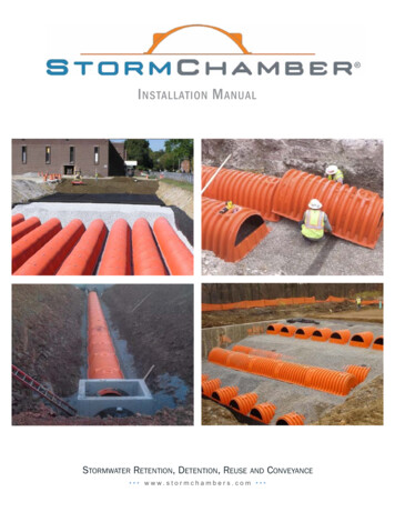
I nstallation M anualStormwater Retention, Detention, Reuse and Conveyance www.stormchambers.com
Before Your Stormchambers Arrive1. StormChambers will arrive either on a flat bedtrailer or in an enclosed van. If in an enclosedvan, we will try our best to have the driver loadthe pallets at the tail of the van. However, beprepared with a long chain, metal cable, orstrong rope or straps to drag a pallet from thenose of the van. A forklift is the easiest way tounload pallets of StormChambers .to minimum of 6" (150 mm) above theStormChambers . Do not use limestone.Limestone gets pasty when wet and will tend toseal-off the bottom of the trench and reduce thevoid spaces in the stone.4. 4’ (1,200 mm) sections of 10” (250 mm) (unlessotherwise specified), Schedule 40 or SDR 35PVC pipe for the interconnections between rowsof StormChambers (check plans for numberand location of interconnections).5. 12” (300 mm) bell and gasket Schedule 40 orSDR 35 PVC pipe for inspection/clean out risers(check plans for number and location of risers).6. Cleanout caps or tops for inspection/clean out risers.7. One manhole cover frame and lid for eachinspection/clean out riser in pavement (EastJordan V – 8450 or equivalent).8. Concrete and related materials to form 3’ x 3’(900 mm x 900 mm) reinforced pads to holdmanhole cover frames and lids for inspection/clean out risers.Equipment Needed1. Forklift or other type of equipment to unloadStormChambers .2. Excavator to dig the trench and to place stoneand soil backfill.3. Two battery or power operated screw guns toconnect bases of overlapping StormChambers .4. Sawzall, router bit on a drill, or key holesaw to cut open side and top portals inStormChambers .2. A full pallet of StormChambers will weighapproximately 3,410 pounds (1,550 kg), will beabout 5’ (1,525 mm) wide, 8.5’ (2,590 mm) long,and approximately 8.5’ (2,590 mm) high.Materials Needed1. Wire cutters to remove the metal bands thatsecure the StormChambers to their pallets.2. 3” (75 mm) drywall screws to screw theoverlaying bases of the StormChambers together until the stone is placed around them.5. Light weight, tracked dozer, not exceeding 1,100lbs (500 kg)/sf to grade backfill.6. Hand – operated compactor, small roller, ortracked vehicle for fill compaction. Trackedvehicle must not exceed 1,100 lbs (500 kg)/sf;hand operated compactor or vibratory roller mustnot exceed a dynamic force of 20,000 lbs (9,000kg).7. Transit or laser.8. Stone bucket.3. 3/4”- 2” (20 mm-50 mm) crushed, washed,hard stone for the trench base and to backfillPlease note that all photographs and illustrations are for illustrative purposes only. Please rely on what the engineer specifies.1 www.stormchambers.com
When Your StormChambers Arrive1. UNLOADING – see “Before YourStormChambers Arrive” above. As a lastresort, the pallets can be dragged off of thetrailer and dropped on the ground. This will notinjure the StormChambers .2. Confirm the total number of StormChambers ,SedimenTraps , light and heavy duty netting,filter fabric and any other items listed on yourpurchase order. Contact StormChamber immediately if the count is incorrect.3. Confirm the number of Start, Middle and EndStormChambers . Each pallet should be markedwith the number of each.4. Check all StormChambers andSedimenTraps for damage and contactStormChamber immediately if any sign ofdamage is present.5. During periods of excessive and/or extended hotweather please take one chamber at a time offof a pallet, just before placing it in the trench.Do not allow chambers to be left on their backs,exposing the underlying black color to the sun.If possible, keep pallets of chamber and backfillstone in the shade. Try to resrict chamberinstallation to the cooler morning periods. Placestone and soil backfill on chambers as the arebeing installed.Trench Preparation1. Do not excavate trench until dry weather isforecast long enough to allow at least covering theStormChamber system with filter fabric prior toraining to avoid soil filling void spaces in the stone.2. Excavate to a width and length sufficient toaccommodate the number of StormChambers plus a minimum one foot border around the entireStormChamber system. The bottom of the bedmust be level.3. If the StormChamber system was designed forinfiltration and heavy clays are encountered, thesurface of the trench bottom must be scarified withthe prongs of the excavator before placing thestone base.4. Do not use heavy equipment on the excavatedtrench bed in order to avoid soil compaction.5. If it is not possible to excavate the entire trenchfrom outside the trench, have the excavator backup as it excavates in front of it in order to avoidcompaction of underlying soils.6. If use of heavy equipment on the excavated trenchbed can not be avoided, scarify the trench bottomand break up soil clumps before adding the stonebase.7. Line trench walls with StormChamber filterfabric. Overlap adjacent filter fabric by at least2’ (600 mm). Do not place filter fabric underthe StormChambers . The filter fabric willclog, restricting the infiltration capability of theStormChamber system.2 www.stormchambers.comLine trench walls, not trench bottom, withStormChamber filter fabric.8. Unless otherwise specified, place 6” (150 mm) ofcrushed, washed, 3/4” to 2” (20 mm-50 mm) noncalcarious stone on the bottom of the trench.9. If it becomes impractical to level the stone baseby hand, use a low pressure, tracked dozer, notexceeding 1,100 lbs (500 kg)/sf, maintaining atleast 6” (150 mm) of stone under the tracks at alltimes.10.Do not use the excavated trench as asedimentation trap or sediment basin duringconstruction. The fine soil particles will accumulateat the soil boundary and restrict the infiltrationcapability of the system.
InstallingtheStormChamber SedimenTrapTMMost StormChamber systems are specified with our SedimenTraps . The SedimenTraps are used asa low cost and highly effective method to capture and facilitate removal of sediment.1. StormChamber systems typically incorporate SedimenTraps at the first and last chamber of therow(s) receiving the storm water inflow. StormChamber systems are installed by placing all StartModels first, then building each row equally with Middle Models and finish building the rows with theEnd Models.2. Working from the Start Models end of the StormChamber system, identify the location for the firstSedimenTrap . The SedimenTrap must be located so that the bottom is aligned exactly under the12" (300 mm) PVC riser pipe of the chamber over it.3. Excavate a hole deep enough so that theSedimenTrap , when placed on about 6” (150mm) of a crushed, washed 3/4" – 2” (20 mm-50mm) non-calcarious stone base, only the topcorrugation of the 30” (750 mm) HDPE pipesection will be exposed above the finishedtrench stone base (about 3" (75 mm)).4. Fill around the SedimenTrap with the crushed,washed 3/4" - 2" (20 mm-50 mm) non-calcariousstone.5. Cut the heavy weight stabilization netting to fitsnuggly under the exposed corrugation of theSedimenTrap .6. Place the Start Model over the SedimenTrap and install the 12" (300 mm) PVC riser pipe asshown in the above drawing. Cut a hole in thetop portal for a 12” (300 mm) SDR 35 or PVCSchedule 40 riser pipe along the indented circle.Attach about a 1' (300 mm) piece of the pipeinto the bell and insert the short piece into thetop portal, allowing the bell end to rest on theStormChamber portion that surrounds the topportal hole. If the cut extends more than 0.5”(13 mm) beyond the cut out, place a piece of3 www.stormchambers.com
the StormChamber non-woven filter fabric over the hole, cut an X slightly shorter than the width of theopening, and insert the pipe. The purpose of the bell end is simply to support the pipe until the backfill isplaced. Insert the bottom 1’ (300 mm) of pipe into the top portal and backfill. Place a manhole cover frameand lid in a 3' x 3' (900 mm x 900 mm) reinforced concrete pad above, once all fill is placed, for risers inpavement. PlacingtheStormChambers1. Start building the StormChamber system withthe Start Model StormChambers at the inflowend of the StormChamber system. The StartModels are completely closed at the end with thetwo side portals.3. Place one piece of the StormChamber heavyweight stabilization netting (provided with theStormChambers ) under each StormChamber that will be receiving inlet storm drain pipes.Place on top of the light weight netting andextend beyond all edges of the StormChamber as shown below. The purpose of the heavyweight stabilization netting is to function asa “splash pan,” preventing scouring of theunderlying stone and soil, while allowinginfiltration to occur.Row placement begins at inflow end of chambersystem with Start Model StormChambers .2. Roll out a row of light weight stabilization nettingunderneath the entire row of StormChambers that is receiving inlet storm drain pipes and theadjacent row(s).Place heavyweight stabilization netting under chambers receiving storm drain inflow, and light weight netting underrow(s) receiving inflow and adjacent row(s).4 www.stormchambers.com
4. Place the Start Model StormChambers asshown above, (completely closed at the end withthe two side portals), spaced a minimum of 5’ 9”(1,750 mm) apart at the center line of the endwalls (9” (230 mm) apart at the base). Positionthe closed ends at least 1’ (300 mm) from thetrench wall.6. If a cut extends more than 0.5” (13 mm) beyondthe intended diameter, place a piece of theStormChamber non-woven filter fabric overthe hole, cut an "X" just short of the width of theopening, and insert the pipe. The connectiondoes not need to be water tight. 10” (250 mm)PVC pipe is the largest diameter pipe that can beinserted into the side portals. The end walls canaccept up to a 30" (750 mm) O.D. pipe.Insert PVC row connecting pipes.5. Cut open the side portals for the inflow stormdrain pipes (size and location specified on theplans) and lateral connecting pipes betweenStormChamber rows 10" (250 mm) Schedule40 or SDR 35 PVC) with a reciprocating saw,router bit on a drill, or keyhole saw along thedefined indented circle. If the inflow storm drainpipe is specified to enter the closed end wall,place a piece of the pipe against the end wall.Trace the diameter of the pipe on the end walland cut out the circle.7. Mark the midpoints of 10" (250 mm) PVCpipe (about 4' (1,300 mm)) and insert into theadjacent StormChambers where specified sothat the marked midpoint is centered betweenthe two adjacent StormChambers . Pipe lengthshould be sufficient to extend 6” (150 mm) – 12”(300 mm) into both adjacent StormChambers .In order to facilitate placement, install thelateral connecting pipes in the specifiedStormChambers before attaching the nextStormChamber in the row.8. If the locations of row – connecting pipes arenot specified, add PVC pipes only between theinflow row and adjacent row(s).9. Roll out additional StormChamber light weightstabilization netting, over-laying the previoussheet by 1’ (300 mm) and place the first ribof a Middle Model (completely open at sideportal end, partially open at top portal end)over the last rib of each of the Start ModelCut out side portals for PVC inflow pipe and rowconnecting pipes. Cut out indentation guides areprovided for 10" (250 mm) PVC.5 www.stormchambers.com
After placing all Start Models, build each rowequally with Middle Models and finish buildingthe rows with End Models.Place first rib of a Middle Model, over last rib ofeach Start Model.10.Screw the StormChambers together near theirbase on both sides with regular 3” (75 mm) drywall screws. One screw on each side is sufficientto temporarily hold the StormChambers togetheruntil the stone is placed. The gap between the twoStormChambers near their base must be closedenough to prevent stone from migrating into themto prevent potential surface subsidence.End each row with an End Model StormChamber which is closed at the top portal end and open atthe side portal end.13.If inspection/clean out risers are specified withouta SedimenTrap , follow the instructions in #5 onpage 5.Place heavyweight stabilization nettingunder chambers with cleanout risers whenSedimenTraps are not used.Screw StormChambers together at base toprevent stone inflow.11. Continue placing and screwing the rest of theStormChambers , one at a time, inserting anyadditional lateral – connecting pipes as specified.12. leaving at least 1’ (300 mm) between the end ofthe End Model (completely open at the side portalend, completely closed at the top portal end) andthe trench wall.6 www.stormchambers.com14.Deposit 3/4” – 2” (20 mm-50 mm) crushed,washed, hard stone directly along the centerlineof the StormChambers to evenly flow downeach side to keep the StormChambers inproper alignment. DO NOT use limestone.Limestone gets pasty when wet and will tend toreduce the void spaces in the stone.
IMPORTANT: If a low pressure, tracked dozer isused, do not run the dozer on anything less than6” (150 mm) of stone above the StormChambers .Spread stone in small piles to prevent movement ofthe StormChambers . Caution must be exercisedwhen placing stone on top of the StormChambers so that excessive pressure is not applied directly onthe StormChambers by equipment “buckets”.16.Cover the stone with StormChamber filter fabric. Overlap adjacent sheets by at least 2’ (600mm).Deposit 3/4” – 2” (20 mm-50 mm) crushed, washed,hard stone directly along the centerline of the StormChambers .15.Level the stone cover with a vibratory compactor,not to exceed a dynamic force of 10,000 lbs (4,500kg), or with a low pressure, tracked vehicle notexceeding 1,100 lbs (500 kg)/sf.Backfilling1. Backfill soil must be free from large stonesand large organic material (e.g. tree limbs androot stumps), and must be capable of beingcompacted to at least 95% of the Standard ProctorTest (AASHTO Method T – 99). If not, crusherrun or other suitable backfill material must beused. The same type of stone surrounding theStormChambers can also be extended up to thepavement sub grade, if desired.2. Compaction of the soil backfill must be done inlifts 6” – 8” (150 mm-200 mm) high. Grading oflifts should start in one corner of the system witha low pressure tracked dozer, with a pressure notexceeding 1,100 lbs (500 kg)/sf, keeping at least1'(300 mm) of fill in front of the blade at all times.Compact lifts to at least 95% Standard Proctor withtracked vehicles not exceeding 1,100 lbs (500 kg)/sf, or with a hand operated compactor or vibratoryroller not exceeding a dynamic force of 20,000 lbs(9,000 kg).3. Restrict wheeled vehicles to a maximum axleload of 8,000 pounds (3600 kg) with 6” (150 mm)of fill over the StormChambers and 16,000pounds (7200 kg) with 12” (300 mm) of fill.7 www.stormchambers.com4. Keep the StormChamber system closed or protectedfrom receiving sediment until the site is completelystabilized.IMPORTANT: After compaction of backfill and settingof final grade, avoid parking on or traversing overthe StormChamber installation with heavily loadedtrucks and heavy equipment until paved.IMPORTANT: These instructions assume acceptedconstruction procedures and loaded trucks that donot exceed specified DOT load limits. Uncustomaryloads or improper load distributions in vehicles mayrequire additional cover. Contact StormChamber forinstallation under abnormal conditions. Installationsnot in compliance with these instructions will void thewarranty.Contact StormChamber for technical assistance at1.877.426.9128 or email us at info@stormchambers.com.
Contact Information(877) 426-9128 (Toll-Free)info@stormchambers.com (Email Us)www.stormchambers.comStormChamber Limited WarrantyStormChamber will warranty the structuralintegrity of each system in accordance withthe installation instructions and is warranted tothe original purchaser against defective materialsand workmanship for one year from the date ofpurchase. It is the responsibility of the purchaserto inspect the StormChamber units prior toinstallation and to inform StormChamber of anydefect prior to installation. StormChamber willonly be responsible for supplying replacementStormChamber unit(s). StormChamber liabilityspecifically excludes the cost of removal and/orinstallation of the units.There are no other warranties with respect to theunits, including no warranties of merchantabilityor fitness for a particular purpose. This warrantydoes not extend to incidental, consequential,special, or indirect damages. The company shallnot be liable for penalties or liquidated damages,including loss of production and profits, laborand materials, overhead costs, or other loss orexpense incurred by buyer. Specifically excludedfrom warranty coverage is damage to theunits due to ordinary wear and tear, alteration,accident, misuse, abuse or neglect of the units,improper construction protocols, installation ofthe units not consistent with StormChamber installation instructions, placement by buyerof improper materials into buyer’s system, orany other event not caused by the company.StormChamber shall not be responsible forany loss or damage to the buyer, the units, orany third party resulting from its installation orshipment. Buyer shall be solely responsiblefor ensuring that installation of the system iscompleted in accordance with StormChamber installation instructions and with all applicablelaws, codes, rules and regulations.Inspect all shipments within 5 days of receiptof StormChambers . Failure to adviseStormChamber of defects on shipments withinthis period will constitute acceptance of theshipment.This warranty shall not apply to any partyother than the original buyer. Furthermore, nocompany representative has the authority tomodify or change this warranty in any manner.The StormChamber is protected by the following U.S. Patents: 6,612,777; 469,187; 465,545; D469,187;D465,545; 6,719,490; 6,994,490. Canadian Patents: 2,356,592; 2,491,126. Other U.S. foreign andCanadian Patents Pending.Printed in U.S.A. Copyright. All rights reserved. HydroLogic Solutions, Inc.8 www.stormchambers.com
defined indented circle. If the inflow storm drain pipe is specified to enter the closed end wall, place a piece of the pipe against the end wall. Trace the diameter of the pipe on the end wall and cut out the circle. Cut out side portals for PVC inflow pipe and row connecting pipes. Cut out indentation guides are provided for 10" (250 mm) PVC. 6.