Transcription
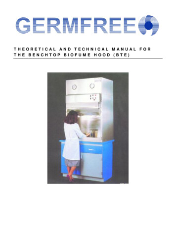
THEORETICAL AND TECHNICAL MANUAL FORTHE BENCHTOP BIOFUME HOOD (BTE)
GERMFREETheoretical and Technical Manual for theBenchtop Biofume Hood ( B T E ) Germfree Laboratories Incorporated11 Aviator Way Ormond Beach, FL 32174Phone 800.888.5357 Fax 386.677.1114www.germfree.com
Table of ContentsIntroduction1Services4Installation10Test Mode11Environmental Testing12Operation13Performance Testing14Air Balance15Airflow Smoke Test16Working in the BTE17Some Biological “Don’ts”19Airflow Diagram20V E N T I NGR E C O M M E N DA T I ON SBTE 4SS21BTE 6SS22D I A G RA M S3SS234SS246SS25Wiring26Parts List27
G E R M F R E EIntroductionDuring the past few decades, there has been an increase in the use ofClass II Laminar Flow Biological Safety Cabinets. These units weredesigned to contain low and moderate risk microorganisms, but did notprovide for non-particulate materials that could pass through the supply HEPAfilters. The Total Exhaust BENCHTOP BIOFUME HOOD differs from otherClass II Laminar Flow Biological Safety Cabinets in that no air recirculates in thecabinet. Therefore, there is no possible buildup of any non-particulate material inthe work area. In contrast, within a hood in which air recirculates, non-particulatematter passes through the HEPA supply filter into the work area. Thus, theBENCHTOP BIOFUME HOOD can be used for one or any combination of thefollowing biohazards:CarcinogensRadioactive gasesPotentially infectious materialsVolatilesNoxious fumesSubliming particulatesBesides ease of operation, the BENCHTOP BIOFUME HOOD providespersonnel and environmental protection from the aforementioned potentialhazards, and concurrently, offers product protection against cross-contamination.Tissue culture and other sophisticated techniques frequently require that a varietyof substances be used within the same hood at different times and, notinfrequently, at the same time.The inward air velocity required by various governmental agencies to handle theabove classes of potentially hazardous materials has been reported as 100, 125 and150 linear feet per minute (fpm). Because of the inability of available Class IIcabinets to provide complete protection, particularly from carcinogens and1
radioactive gases, it was apparent that a new concept in Biohazard Cabinetry wasneeded that would meet four basic requirements:1.2.3.4.The protection of personnel and the environment fromexposure to potentially contagious particulates such asbacteria, viruses, parasites, fungi, etc.The protection of personnel and the environment fromnoxious fumes, potential carcinogens and radioactivematerials, by totally exhausting air from the cabinet.The establishment of a work area bathed with laminar flow,containment-free air for the protection of materials.The provision of free ingress and egress of the operator’s handsthrough a partially open front.These features have been incorporated in GERMFREE’s BENCHTOPBIOFUME HOOD. The BENCHTOP BIOFUME HOOD is a verticaldownflow, unidirectional, laminar flow unit that differs from other Class II unitsbecause THERE IS NO RECIRCULATION OF AIR. All air is totallyexhausted. Technologists now can have a far greater sense of security knowingthat air passing over their hands and forearms is not contaminated.The BENCHTOP BIOFUME HOOD has dual capabilities. It may be used as aBIOFLOW CHAMBER when working with potentially contagious particulatessuch as bacteria, viruses, fungi, parasites etc., and/or it may be used for chemicalcarcinogens and radioactive materials, with the outstanding feature that the workarea is bathed with laminar flow sterile air. This degree of personnel, product andenvironmental protection was not previously available for work with nonparticulate materials.The BENCHTOP BIOFUME HOOD exceeds the requirements for a Class 100chamber as described in Federal Standard No. 209. This Standard outlines aircleanliness classes and certain other environmental conditions of air required forachieving and maintaining clean environmental levels. Federal Standard Class 100is that class where particles 0.5 micron or larger must not exceed a total count of100 particulates per cubic foot.Biomedical engineering and technology have introduced safeguards into the designof laboratory equipment but these safeguards cannot prevent human error!2
Danger to personnel from carelessness or improperly used equipment cannot beover-emphasized. There is NO substitute for safe, proper technique.3
ServicesThe BENCHTOP BIOFUME HOOD is shipped complete with the followingaccessories: variable speed blower motor control for supply blower (BFA-5); dualmagnehelic gauges (BFA-14); metal diffuser below supply filter (BFA-15); and airexhaust failure alarm system. To make this hood operational, it must be hookedup to an exhaust fan and a venting system. The unit is provided with both supplyand exhaust HEPA filters.To move the unit through narrow doors, the light housing can be detached byremoving four screws. Also, the viewing panel with the attached light housing canbe removed by sliding the split hinges to the left after raising the panel until it isparallel to the floor. This reduces the width of the BIOFUME HOOD to 30inches. An additional 3/4" clearance is required for the two clamps located belowthe viewing panel.All controls are front-mounted, allowing the unit to be placed side-by-side withother laboratory equipment and flush against the wall. Do not place the unitwithin an area of excessive air turbulence or one subjected to high traffic. Test theselected area with cigarette or chemical smoke and observe the movement of air.ELECTRICAL:All electrical components, except the supply motor and pressure switch, aremounted in the control panel affixed to the front of the hood. There are noelectrical components in the biologically contaminated air stream. A nine-footlong power cord with a molded-grounded plug exits from the control panel on theright hand side as you face the cabinet. Electrical requirements for the hood are(one) 15 amp, 115-volt electrical outlet. Variations in line voltage may causechanges in blower performance.CONTROL PANEL:Components located on the face of the control panel are as follows:2 amp circuit breaker (light)10 amp circuit breakerAudible alarmPilot lights (2), red & greenStart button4
Stop buttonOn-off rocker switches (2)Switch top-main/bottom-fluorescent lightsSpeed control for supply blowerThe control panel can be removed by unscrewing the two acorn nuts located ateach end. All components are mounted directly on the removable control panel.Located inside the control panel is the internal circuitry and the ballast for thefluorescent lights. Please note: wires leading to the supply motor and pressureswitch are threaded into the control panel through grommets in the upper righthand corner. Care should be taken when removing this panel that these wires arenot disconnected.A three-piece stainless steel shroud is attached to the unit to conceal the supplyblower-motor, exhaust filter, etc. It is attached to the sides on the top with studsand nuts. The front piece houses the Magnehelic gauges and is key locked to thesides. This can be lifted off the unit for servicing once the control panel isremoved by raising it up and out.MAGNEHELIC GAUGESMagnehelic gauges measure differential pressures across the supply and exhaustfilter. This information is to help determine filter loading. Each filter has its owngauge because of differential pressures and the possibility of differential loading.They are marked “SUPPLY” and “EXHAUST”. The “SUPPLY” is connected tothe high-pressure side and usually reads greater than .50 inch. The “EXHAUST”is connected to the low-pressure side and usually reads approximately .25 inch.The connection on the exhaust gauge takes its reading from the contaminated airstream. Disconnection of the exhaust should only be undertaken after the unit hasbeen decontaminated. Readings in the Magnehelic gauges vary with eachindividual set of filters and therefore is not a finite number. It is recommendedthat you take note of this setting once the hood has been initially certified andmonitor it (monthly readings are frequent enough for most applications).VARIABLE SPEED MOTOR CONTROLThe variable speed motor control for the supply blower is located beneath thehole plug. Casual adjustment should not be done. The control has been set inthe factory according to our remote exhaust system, based on a total exhaust5
volume of 525 cfm for the BTE 3SS, 700 cfm for the BTE 4SS and 1050 cfm forthe BTE 6SS.Upon completion of installation, it is strongly recommended that certification by aqualified in-house technician or independent agent be carried out. This is alsorecommended as an annual service requirement and any time the unit is moved.DO NOT ADJUST THE SPEED CONTROL WITHOUT GOOD REASON.In addition, we recommend that the airflow pattern be periodically checked usingthe Airflow Smoke Test (page 14) as a guideline. This will insure that properairflow pattern is present.FLUORESCENT LIGHTSThe ballast for the fluorescent lamps is located inside the control panel. Thebottom rocker switch in the control panel turns on the fluorescent lights that aremounted in a separate special housing outside the viewing panel. The cable, whichexits from the upper right hand corner of the light housing, must be connected toits plug located in the right hand side of the control panel.The stainless steel housing provided for the fluorescent lights is attached to thetop of the viewing panel outside of the work area. This location provides the bestglare-free view for the operator and also prevents heat build-up within the cabinet.The electric circuit for the lamps is independent of the wiring to the motorblower. When the viewing panel is raised the ensuing safety shutdown does notinterrupt the power to the fluorescent lights, providing good visibility within thework area at all times.To change the fluorescent tubes or when other work must be performed, turn offthe light switch, disconnect the electric cord to the chamber (receptacle located onright side) and remove the four screws that attach the light housing to the viewingpanel frame. The light housing is now completely disconnected and can be carriedto the appropriate work area. Standard fluorescent components are used.UV LIGHT OPTION1. Fluorescent lights and UV lights cannot be on at the time.2. DANGER – Ultraviolet radiation emitted from this product. Avoidexposure. ALWAYS WEAR PROTECTIVE CLOTHING.EXPOSURE MAY CAUSE PREMATURE AGING OF THE SKIN6
AND CANCER. ALWAYS WEAR PROTECTIVE EYEWEAR;FAILURE TO DO SO MAY RESULT IN SEVERE BURNS ORLONG TERM INJURY TO THE EYE. Never look directly into thelamp. Exposure can cause eye and skin allergy and allergic reactions.Medications or cosmetics may increase your sensitivity to ultravioletradiation. Consult physician before operating this product if you are usingmedications or have a history of skin problems or believe yourselfespecially sensitive to sunlight.”3. WARNING – Do not operate without protective shield on UV light bulb.4. WARNING – Do not work in the biofume hood while the UV light is on.STOPCOCK (VALVE) OPTION1. Warning: Do Not connect flammable fluids, gases or substances to theoptional valves (stopcocks) if provided.2. The maximum pressure is 30psi.3. Overpressure safety device must be installed to limit pressure ofsubstances coming into the fumehood.FILTERSIn the BENCHTOP BIOFUME HOOD the supply HEPA filter is locatedimmediately over the work area; the exhaust HEPA filter is placed at the finalpoint of air discharge. These filters are sized to provide optimal safety andperformance. All filters were integrity tested with dioctlyphthalate (DOP) orequivalent and scanned with a photometer by their manufacturer and again in ourfactory. They are certified to be 99.99% effective for DOP particles 0.3 micron insize. As is the nature of HEPA filters they are even more effective for both largerand smaller particles.Loading time for both filters will depend primarily on the number of particlesgenerated within the chamber. Under normal laboratory conditions, the life of thefilters should be four to five years. Occasionally they may become obstructed inthree years or less. In a very clean environment, HEPA filters may remaineffective for six or more years.7
VIEWING PANELThe viewing panel is fabricated of polycarbonate plastic. A number of chemicalshave an adverse effect on polycarbonates plastics. Never use gritty soaps orhousehold cleansers such as Comet or Ajax.Polycarbonate is unaffected by most inorganic solvents, mineral and animal oils,low concentrations of alcohols, paraffinic and olefinic hydrocarbons, amines, alkylmonhalides, esters containing more than ten carbon atomes, alkalies, nonoxidizing acids, salt water, photographic solutions and chemicals petroleum oilsand grease, household cleaning products and chemicals used in treating water.For cleaning 50% Ethyl alcohol, 70% Isopropyl alcohol, or a 5% Bleach solutioncan be used, DO NOT use 95% or 70% Methyl alcohol or Windex.The viewing panel is held in place with toggle clamps. These are screwed in andcan be removed if necessary for transportation into a room. The unit is notdesigned to be operated without its viewing panel. The viewing panel is hinged soit can be easily opened for placement of larger objects into the work area. It canbe removed by releasing the snap ring, lifting the panel and moving it to the left.The snap ring prohibits accidental removal of the panel from its hinges.ALARM SYSTEMThe BENCHTOP BIOFUME HOOD has, as standard equipment, an ExhaustFailure Alarm System. The Alarm System consists of pilot lights, a sound alarmand pressure switch. This alarm system provides the user with added safety andalso alerts the user if an airflow problem is present. Basically, should there be anexhaust fan failure, the supply blower will automatically shut off, the red pilot lightwill turn “ON” and the sound alarm will be activated.This failure system eliminates the possibility of the supply fan operating withoutthe exhaust fan, which could possibly discharge contaminated air into the room. Ifthis situation occurred, personnel would be alerted. Conversely, should the supplyfan fail, the sound alarm will ring and the exhaust fan would continue to operate,allowing the worker to complete his work.8
The Alarm System consists of pilot lights, sound alarm and pressure switch. Thepressure switch comes wrapped in plastic that is taped to the top of your unit. Itmust be mounted on the exhaust transition piece, which connects the exhaustHEPA filter to the in-house ductwork. This should be done by your maintenancedepartment or the contractor installing the hood. The pressure switch comescomplete with a quick electrical disconnect and junction box mounted on the topof the BENCHTOP BIOFUME HOOD.D.O.P. PORTSD.O.P. ports have been supplied for upstream concentration readings of both thesupply and exhaust filter. The D.O.P. port located on the left-hand side of the reararea should not be opened without decontaminating the unit first.9
InstallationNOTE: The BENCHTOP BIOFUME HOOD has NO internal exhaust fan andrequires hook-up to an external exhaust ventilation system.Class II biohazard cabinetry should be located out of the traffic pattern and awayfrom room air current which could disrupt the air containment barrier. If there is awindow in the laboratory it should remain closed at all times. The cabinet shouldnot be placed near room air vents. A smoke test to evaluate possible locations willassist in determining the cabinet’s proper location.The Total Exhaust BENCHTOP BIOFUME HOOD is a Class II, Type B2Laminar Flow Biological Safety Cabinet. Type B2 cabinets are to be ventedoutside the building without recirculation. Venting should include an exhausttransition piece, leak-tight duct work, damper in the duct near the cabinet for flowadjustment and decontamination and an external exhaust blower at the duct’sdischarge. The exhaust fan should be sized to deliver the required exhaust airflow,as specified, taking into account the pressure losses in the duct and exhausttransition piece and allow at least 2 inches water gauge to compensate for a dirty,fully loaded HEPA filter. It is recommended each Type B2 cabinet have its owndedicated exhaust system and that an alarm system be provided (See Alarm System- BTE Series).The exhaust transition piece should be removable from both the exhaust filterhousing and the duct. Servicing and replacement of the HEPA filters requires thisflexibility. (See venting recommendations on page 19 & 20 and the detail diagramsof Top View for the specified hood beginning on page 21.)Once hook-up is complete, it is recommended that the hood be certified. If youdo not have this service in-house, or know of an independent agent, pleasecontact the factory, as we will be happy to supply names of independent qualifiedrecertification organizations servicing your area.10
Test ModeMAIN Switch turned “ON” (external exhaust fan and supply fan turned “OFF”);system is set for testing. Red light and alarm should be “ON”. This should betested periodically to insure proper function of alarm system.OPERATION1.Exhaust Fan OFF, Supply Fan OFF, Main Switch “ON” (Test Mode).a)Red light “ON”b)Sound alarm “ON”c)Green light “OFF”2.Exhaust Fan “OFF”a)Supply fan will not startb)Red light “ON”c)Alarm “ON”d)Green light “OFF”3.Exhaust Fan “ON”.a)Supply fan can be startedb)Green light “ON”c)Alarm “ON”d)Red light “OFF”4.Exhaust Fan “ON” Supply Fan “ON”.a)Green light “ON”b)Red light “OFF”c)Alarm “OFF”5.Exhaust Fan Failure.Same as (2) above.NOTE: IF EXHAUST FAN FAILURE HAS OCCURRED AND BEENCORRECTED, THE START BUTTON WILL HAVE TO BE PUSHED TOSHUT THE ALARM OFF.11
Environmental ConditionsThe BTE can be operated safely under the following conditions:A) Indoor UseB) Altitude up to 2000mC) Temperature 5 C to 40 CD) Maximum relative humidity: 80% for temperatures up to 31 decreasinglinearly to 50% relative humidity at 40 CE) MAINS supply voltages fluctuations up to 10% of the nominal voltageF) Transient overvoltages typically present on the MAINS supply.(Note: The normal level of transient overvoltages is impulse withstand(overvoltage) category II of IEC 60364-4-443)G) Applicable RATED POLLUTION degree: 212
Operation – BTE SeriesTo operate your BENCHTOP BIOFUME HOOD the following installation isrequired:1) Connection to an external exhaust system, which consists of anexhaust transition piece, duct work and external exhaust fan. (Seeinstallation - BTE Series).2) Installation of pressure switch (part of Exhaust Failure Alarm System)in exhaust transition piece.3) Electrical receptacle; grounded, 20 or 15 amp (without outletreceptacle) for power cord.NOW YOU ARE READY TO TURN YOUR HOOD “ON”1) Activate exhaust fan (this step varies from institution to institution).2) Turn main switch “ON”; fluorescent lights can only be turned on aftermain switch has been engaged.3) Press START button.Allow 15 minutes to pass prior to undertaking any activities in the hood or priorto turning off the hood.To shut down, carry out the same procedure in reverse.13
Performance TestingYour BENCHTOP BIOFUME HOOD features one-piece welded construction.No access panels are required and there are no jointed segments that might loosenduring shipment. This is a distinct advantage because many potential sources ofleakage through gaskets are avoided. Your BENCHTOP BIOFUME HOOD hasbeen tested at the factory. Dioctylphthalate (DOP) or equivalent was aerosolizedand circulated by the supply fan and the integrity of the supply HEPA filterdetermined by scanning with a photometer to detect aerosol particles on thedownstream side of the HEPA filter. The exhaust HEPA filter integrity wasdetermined by scanning the filter and filter housing after vaporized DOP wasintroduced into the cabinet. If there was any penetration through the filtermedium or perimeter filter seal, the leaks were repaired. Your BENCHTOPBIOFUME HOOD was certified to be leak-free when it left the factory.Downward air velocity was determined to be uniform and unidirectional with athermoanemometer. The probe was placed in the unit, 4” above the bottom edgeof the viewing panel and readings were taken at 6" spaced intervals side to sideand 5¼” front to back. Other tests for noise, vibration, and light intensity wereperformed. The BENCHTOP BIOFUME HOOD meets or exceedsrecommended standards.14
Air BalanceIt is extremely important that the air be balanced before the BENCHTOPBIOFUME HOOD is initially utilized, and from time to time thereafter, thefrequency is dependent on the type of work. Air balancing is performed in thefactory by adjusting the speed controls in the locked control panel. CAUTION:These settings may have been changed during or after delivery. It is imperativethat the following procedures be carried out before the cabinet is used. Releasechemical smoke inside the cabinet at various heights above the work tray. Thesmoke should be pulled through the perforations of the work tray support withoutescaping through the access opening of the viewing panel. Smoke from a sourcelocated outside the unit in front of this opening should be pulled down throughthe perforations in front of the work tray without passing over it.The variable speed control for the blower is set so that the air downflow in thework area averages in the 55-65 fpm range. The speed control is adjusted to insurethat smoke released within the work area is contained and smoke placed in frontof the viewing panel does not pass over the work tray. To calculate the air inflow,first subtract the volume of air (cfm) passing through the supply filter from thetotal quantity of air passing through the exhaust filter. Dividing this remainder(cfm) by the access opening (measured in square feet) gives the inflow velocity infpm.(value of air entering front window) ft.3 /min. (velocity of air through front window) ft./min.(area of front window) ft.2The BENCHTOP BIOFUME HOOD has been tested under simulated workconditions. This testing was two-fold. Challenges were designed to prove theintegrity of the unit in containing potentially hazardous materials and todemonstrate that work within the hood would be protected from outside airinterference or contamination.15
Airflow Smoke TestThis basic test is used as a guide for balancing the airflow. A source of visiblesmoke is required.The exhaust motor blower and the supply motor blower must be balanced. Whenthe source of smoke is held outside the cabinet in front of the work accessopening, the smoke should go into the front angled tray support, but not over thework tray. If the smoke goes over the work tray, then the motor blower should berebalanced. When the source of smoke is held inside the cabinet above the worktray, the smoke should separate and go into the front and rear angled tray support.If the smoke goes outside the cabinet, then the motor blowers must berebalanced.16
Working in the BTEThe successful use of the BENCHTOP BIOFUME HOOD as a safety tooldepends upon two factors: advance planning and good technique. Even the mostsophisticated and elaborate systems imaginable would be useless if propertechnique were not employed. It is, therefore, the responsibility of the seniorinvestigator or the head of the laboratory to train personnel who will be using thecabinet. If this is not done, a dangerous false sense of security might prevail.Advance PlanningTo achieve maximum safety and utilization of your BENCHTOP BIOFUMEHOOD, assemble equipment and materials needed for the particular operation orexperiment.The best way to accomplish this is with a checklist and/or protocol that includesequipment, apparatus, media, supplies, samples, specimens and other necessaryitems. This checklist should also indicate the order in which procedures will becarried out.Advance planning should include a layout for arranging items in the work area.Contaminated items and clean items must be segregated and the movement ofcontaminated items over clean items should be minimized.Good TechniqueWhen the planning phase is completed, place the clean equipment, supplies, etc.,within the chamber. The viewing panel should only be opened when large itemsare required in the hood. Do not overload the work area. It is important that allmaterials for the complete procedure be in the chamber before starting toeliminate unnecessary movement in and out of the cabinet. CAUTION: Neverblock the perforations of the work tray support with paper, syringes, pipettes, etc.Work must be performed on or over the work tray.Now that all the items on the checklist have been arranged in the work area, turnthe power switch “ON”(Many institutions choose to continuously operate theunit). Wait approximately 15 minutes before starting to work. Smoke testing canbe carried out during this interval. This allows sufficient time for the ultraclean airfrom the HEPA filter within the chamber to remove any airborne contamination17
from the work area and particulate matter from newly introduced equipment andsupplies.The operator is the critical factor in the successful and safe operation of any safetycabinet. A properly balanced and properly utilized BENCHTOP BIOFUMEHOOD will do an excellent job of preventing contamination. Gloves appropriatefor the type of radioactive, biological or chemical material should be used.It is recommended that operators wear long-sleeved gowns with knit cuffs underthe rubber gloves. This minimizes the shedding of skin particles and flora into thework area and protects the hands and arms from contamination. Conventionallaboratory coats with open cuffs that allow the entrapment of contaminated airaround the technician’s forearms should not be used. The hands and forearmsshould be inserted into and withdrawn from the work area slowly to prevent“dragging” of contaminants from the room into the work area or from the workarea into the room. Abrupt movements of the arms and hands should be avoided.Excessive activity in the room may also create disruptive air currents. Obviously,the viewing panel should never be opened while work is in progress.For loop sterilizing, a liquid petroleum (LP) burner or electrical sterilizer isrecommended because it does not block the laminar flow pattern. If a flame isrequired, a microburner with a pilot light is preferred, which should be placedtoward the back of the work area. Do not use a flame of such magnitude that itwill damage the supply filter located above the work area. Ensure that the flame isextinguished and the gas turned off at the stopcock when not in use.When work has been completed, cover the tray for discarded pipettes, planchettes,etc., with a towel soaked in the appropriate deactivating solution. The tray andother equipment (glassware, etc.) also can be wiped or sprayed with an appropriatesolution. Wait approximately 15 minutes before removing any item from thechamber.Through biomedical engineering and advanced technology, we are providing theBENCHTOP BIOFUME HOOD as one of the key elements in the safe handlingof hazardous materials. By utilizing good technique and following the proceduresoutlined, you can protect yourself, the environment and the integrity of yourresearch. YOU ARE THE KEY!18
Some Biological Don’ts1.DON’T neglect to test smoke pattern at fixed intervals.2.DON’T cover the air intake area in front of the chamber with papers,notebooks, equipment, etc. Movement of air into the negative pressuresection must not be impeded!3.DON’T “turn up the air” under the mistaken impression that the fasterthe air flow the better the unit is operating.4.DON’T obstruct the exhaust filter or supply blower opening.5.DON’T perform maintenance in a contaminated hood.6.DON’T overload the work area.7.DON’T carry out procedures in front of work tray.8.DON’T place items in a position that would interrupt the laminar airflowpattern.9.DON’T introduce or remove your hands rapidly into or out of the unit.10.DON’T allow spilled hazardous material to remain in your BENCHTOPBIOFUME HOOD.11.DON’T move contaminated items over clean items.12.DON’T work with open cuffs or other loose garments that might entraphazardous material.19
Airflow Diagram20
VentingRecommendations forBTE 4SS1)2)3)4)5)6)8” to 10” round ductwork or equivalent in square.Tapered exhaust transition to minimize static pressure.Hard connected but removable with minimum 14” clearance for filterchanging.In-line adjustable damper (preferably in duct near cabinet).Leak-tight duct.Requires 700cfm of exhaust air with 2 –2½” of reserve static pressure forloaded HEPA filter.21
VentingRecommendations forBTE 6SS1)2)3)4)5)6)10” round ductwork or equivalent in square.Tapered exhaust transition to minimize static pressure.Hard connected but removable with minimum 14” clearance for filterchanging.In-line adjustable damper (preferably in duct near cabinet).Leak-tight duct.Requires 1050cfm of exhaust air with 2 –2½” of reserve static pressure forloaded HEPA filter.22
BTE 3SS23
BTE 4SS24
BTE 6SS25
Wiring Diagram26
Parts ListFilters:HEPA (High Efficiency Particulate Air) 99.99% efficient probedSupply:Exhaust:BTE 3SS20 x 34 x 6 x 312 x 24 x 6BTE 4SS20 x 48 x 6 x 312 x 36 x 6BTE 6SS20 x 70 x 6 x 312 x 48 x 6Blower, Supply(1) Direct Drive forward curved DD9-7ATMotor Supply(1) 2’ and 3’ —1/3 HP ; 1625 rpm; permanent split(2) 4’ and 6’ —1/2 HP ; 1625 rpm; permanent splitCapacitor7.5 MFD G.E. # 6X655Electrical Light Connector BEAU P-3302-CCT/S-332-ABPressure SwitchDwyer: Model 1910-1Switches (Rocker)GE GX655D 97F9001Switches (Bottom)(1) Start: N.O., microswitch; T11AJ20/233E/23E10(1) Stop: N.C., microswitch; T11AJ10/233E/23E01Relay D(2) Relay Socket OMRON LY2 110/120 VacRelay CE-2039HP Max.15A - 240V(1) Contactor: PRD-11AYO-120 VCircuit Breakers(1) 10 Amp. W58XB1A4A-1
3. The establishment of a work area bathed with laminar flow, containment-free air for the protection of materials. 4. The provision of free ingress and egress of the operator's hands through a partially open front. These features have been incorporated in GERMFREE's BENCHTOP BIOFUME HOOD. The BENCHTOP BIOFUME HOOD is a vertical