Transcription
Quick Start GuideMHM-97430-TW, Rev 1June 2016CSI 2140 Machinery Health AnalyzerQuick Start Guide
Copyright 2016 by Emerson Process Management. All rights reserved.No part of this publication may be reproduced, transmitted, transcribed, stored in a retrieval system, or translated into anylanguage in any form by any means without the written permission of Emerson.DisclaimerThis manual is provided for informational purposes. EMERSON PROCESS MANAGEMENT MAKES NO WARRANTY OF ANY KIND WITHREGARD TO THIS MATERIAL, INCLUDING, BUT NOT LIMITED TO, THE IMPLIED WARRANTIES OF MERCHANTABILITY AND FITNESSFOR A PARTICULAR PURPOSE. Emerson Process Management shall not be liable for errors, omissions, or inconsistencies that may becontained herein or for incidental or consequential damages in connection with the furnishing, performance, or use of this material.Information in this document is subject to change without notice and does not represent a commitment on the part of EmersonProcess Management. The information in this manual is not all-inclusive and cannot cover all unique situations.Trademarks and ServicemarksSee http://www2.emersonprocess.com/siteadmincenter/PM Central Web Documents/marks.pdfME'scopeVES is a trademark of Vibrant Technology, Inc.Bluetooth is a registered trademark of the Bluetooth SIG, Inc.All other marks are property of their respective owners.PatentsThe product(s) described in this manual are covered under existing and pending patents.CE NoticeEmerson Process Management products bearing the symbol on the product or in the user’s manual are in compliance withapplicable EMC and Safety Directives of the European Union. In accordance with CENELEC standard EN 50082-2, normal intendedoperation is specified as follows: 1. The product must not pose a safety hazard. 2. The product must not sustain damage as a resultof use under environmental conditions specified in the user documentation. 3. The product must stay in or default to an operatingmode that is restorable by the user. 4. The product must not lose program memory, user-configured memory (e.g., routes), orpreviously stored data memory. When apparent, the user may need to initiate a reset and/or restart of a data acquisition inprogress. A Declaration of Conformity certificate for the product is on file at the appropriate Emerson Process Management officewithin the European Community.
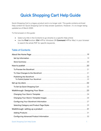
Introduction to the analyzerIntroduction to the analyzerFront viewFigure 1: CSI 2140 front panelA.B.C.D.E.F.G.H.I.J.K.L.Home key - Return to the Home screen from any program.Reset key - Return to the main menu in a program.Function keys - Display menu options.Enter key - Select a menu or option.Keypad backlight key - Turn on the backlight under the keys. (1)LCD backlight key - Set the backlight for the LCD touchscreen.Help key - Display Help text for a key.Power key -Turn the analyzer on or off, or put the analyzer in standby.Battery LED - Green light if the battery pack is charged; amber when charging.Status LED - Blue light flashes each time you press a key or option, blinks in power save mode, andremains solid in standby mode.Arrow keys - Move through menus.ALT key - Display an alternate screen, if available.(1) To comply with relevant safety certifications, the CSI 2140 labeled "ATEX/IECEx Zone 2" does not have a keypad backlight.1
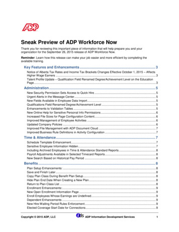
Introduction to the analyzerM.Back key - Back up to the main menu in a program.Top viewFigure 2: ConnectorsA.B.C.D.E.Power supply connector.Ethernet port.Micro USB port.Wireless LED.Bluetooth LED.CAUTION!To prevent damage to the analyzer: Do not connect a signal outside the range of 0 to 24 volts into the Accel input of the CSI2140. Do not connect a signal outside the range of /- 24 volts into the Volts / Tach input of theCSI 2140.Turn on the analyzer for the first timeYou need to activate the battery pack before you can turn on the analyzer for the first time.The battery pack is shipped in storage mode to protect the battery charge. Connect theprovided power supply cord into an outlet and to the analyzer to activate the battery pack.Procedure1.Connect the provided power supply cord into an outlet and to the analyzer.NoteRefer to precautions for the battery pack and power adapter.The Battery LED is amber to indicate the battery pack is charging. The analyzer isactivated.2
Introduction to the analyzer2.Press and hold the power keyto turn the analyzer on.The Home screen appears when you turn on the analyzer. The time and date are setto a default value.3.To set the time and date, press Home ALT F3 Set Time.Battery packA rechargeable Lithium-Ion battery pack powers the analyzer. A typical charge should lastfor more than 8 hours of continuous use. The analyzer displays a low-battery warningwhen the remaining charge reaches a set level; the default is 15 percent. If the batterypack fully discharges, you do not lose any data or settings.The battery pack is shipped in storage mode to protect the battery charge. Refer toTurn on the analyzer for the first time to activate the battery pack.You do not need to discharge or calibrate the battery pack. The hardware optimizesbattery pack performance. Contact technical support if you experience any problems orfor instructions on how to store or replace the battery pack.WARNING!Use only Emerson battery packs with the CSI 2140. The analyzer will not function if a nonEmerson battery pack is used. Lithium-Ion batteries have very specific charging requirements.Emerson power supplies and chargers are designed to work with the Emerson Lithium-Ionbattery pack. Using battery packs other than approved Emerson battery packs could not onlyvoid the warranty, but could also be hazardous.Charge the battery packThe analyzer is fully operational during charging. As a best practice, charge the batterypack frequently. Emerson recommends you charge the battery pack the night before youintend to use it.WARNING! Use only Emerson-supplied power supplies and chargers approved for use with the CSI2140 and Emerson battery packs. Using any power supplies and chargers other thanapproved Emerson power supplies and battery packs could not only void the warranty,but will also most likely damage the analyzer or the battery pack. When charging the CSI 2140 with the battery pack or the battery pack by itself, ensurethe ambient temperature where charging is occurring is 50 F to 95 F (10 C to 35 C). Charge the battery pack only in a non-hazardous area.Procedure1.Remove the rubber plug on the top of the analyzer.2.Insert the power supply connector into the analyzer. The analyzer can be poweredon or off.3
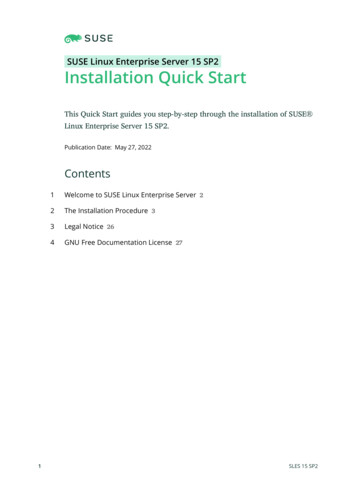
Introduction to the analyzer3.Plug the AC connector on the power supply into a standard AC outlet, ranging from100 VAC to 250 VAC, 50-60 Hz. A full recharge may take four hours.The back of the analyzer may feel warm during charging. The power supply canremain connected to the analyzer after charging completes. You cannot overchargethe battery pack.Attach the shoulder strap1.Press and hold the button on the strap connector, and insert it into the connectorson the sides of the analyzer or the CSI 2140 Four-Channel Input Adapter, if attached.2.To release the strap, press and hold the button on the connector and then pull.Using the stand1.To put the stand in the upright position, grab the stand and pull up until the standlocks.2.To release the stand, place the analyzer face down, grab the base of the stand, andgently pull.The lock releases, and you can push the stand toward the analyzer.Figure 3: Release the standHome screenThe Home screen appears when you turn on the analyzer by pressing the power key.4
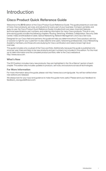
Introduction to the analyzerFigure 4: Home screenA.B.C.D.E.F.G.H.An alternate screen (ALT) includes additional options.Current time and date.Default splash screen.Remaining battery pack charge.Number of supported channels for the analyzer.Serial number.Group number for updating multiple analyzers at one site.Available internal memory.Home screen programs and settingsThe Home screen has two alternate screens that display programs and settings. ALT1 orALT2 appears at the top of the screen and the function keys are outlined in yellow. Toswitch ALT screens, press the ALT key or the ALT text on the touchscreen.ALT1 keysOptionDescriptionF1Intentionally blank.F2 File UtilityCopy, delete, or move routes or jobs saved in the analyzer internal memoryor a memory card.F3Intentionally blank.F4 Set Display UnitsSet the default display units for the measurement values and plots.5
Introduction to the analyzerOptionDescriptionF5 Comm SetupSet the communication options to connect the analyzer to AMS MachineryManager. You can also set up the Bluetooth functionality.F6 Program ManagerUpdate the programs, add new programs, delete unused programs, orchange the splash screen. A password is required to delete programs.F7 Analyze or Adv.AnalyzeCollect data using predefined measurements called Analysis Experts, orcreate your own measurements in Manual Analyze.F8 RouteCollect data using a route created in AMS Machinery Manager. You cannotcreate or modify routes on the analyzer.F9 BalanceBalance a machine. Balance is an optional program that you load onto theanalyzer.F10Intentionally blank.F11 Adv. TransientCollect large, unbroken time waveforms similar to a digital recorder.Advanced Transient is an optional program that you load onto the analyzer.F12 ODS/ModalCollect cross channel data for animated analysis of a machine. ODS/Modal isan optional program that you load onto the analyzer.ALT2 keysOptionDescriptionF1 VersionView the versions of the firmware and programs installed on your analyzer.F2 General SetupModify settings for the analyzer screen, keys, and print functionality.F3 Set TimeSet the time and date in the analyzer.F4 Memory UtilityView information about the internal memory.F5 Battery UtilityView information about the battery pack.F6 View Error LogView information about any errors the firmware generated.F7 Connect ForPrintingConnect to AMS Machinery Manager to print files or screen captures.F8Intentionally blank.F9Intentionally blank.F10Intentionally blank.F11Intentionally blank.F12Intentionally blank.TouchscreenThe touchscreen and function keys let you access the menu options and enter text. If thetouchscreen does not respond accurately, calibrate the touchscreen.6
Introduction to the analyzerWARNING!Clean the touchscreen only in a non-hazardous area. An electrostatic discharge is possiblewhen you clean the equipment exterior. Do not use any abrasive or corrosive chemicals ormaterials. Do not use petroleum distillates and ketone solvents, for example, acetone, gasolineand kerosene. Use a dry, lint-free towel or cloth dampened with a mild soap and watersolution.NoteTo prevent permanent damage to the touchscreen, never use sharp objects or excessive pressurewith your fingers or stylus. Lightly tap the screen.Common analyzer settingsTaskKey sequenceEnable or disable the beeper forkey pressesHome ALT F2 General Setup F2 Set Keypad BeeperSet a timer to enter standbywhen inactiveHome ALT F2 General Setup F4 Set Standby TimeSet a timer to turn off thebacklight when inactiveHome ALT F2 General Setup F5 Set Backlight TimeSet the low-battery warning level Home ALT F2 General Setup ALT F3 Set Warning LevelSet the number of seconds tohold the power key before theanalyzer shuts downHome ALT F2 General Setup ALT F4 Set Hold TimeSet the connection type to usewith AMS Machinery ManagerHome F5 Comm Setup F1 Set Connect PortSet the default display units forall programsHome F4 Set Display UnitsSet the date and timeHome ALT F3 Set TimeView the analyzer firmwareversionHome ALT F1 VersionCSI 2140 Four-Channel Input AdapterThe CSI 2140 Four-Channel Input Adapter expands the capabilities of your CSI 2140 byenabling four inputs.WARNING!Use the CSI 2140 Four-Channel Input Adapter in non-hazardous areas only.The CSI 2140 Four-Channel Input Adapter has two sides that display connectors for Voltsand Accel. Each side has a connector labeled "To CSI 2140". Use the appropriate Interfacecable to connect the CSI 2140 Four-Channel Input Adapter to the CSI 2140. The Accel sidehas a 5-pin connector. The Volts side has an 8-pin connector.7
Introduction to the analyzerConnect to the CSI 2140Attach the CSI 2140 Four-Channel Input Adapter to the shoulder strap connectors on eachside of the analyzer, and press the tabs until they click into place. To release the adapter,press the tabs on each side of the CSI 2140 Four-Channel Input Adapter. To attach theshoulder strap, use the connectors on the sides of the CSI 2140 Four-Channel InputAdapter.Use the appropriate Interface cable to connect the CSI 2140 Four-Channel Input Adapterto the CSI 2140.SideRequired interface cableAccelA40ADAPTR Accel Interface CableVoltsA40ADAPTR Tach/Volts Interface CableFigure 5: CSI 2140 Four-Channel Input Adapter attached to the CSI 2140 without theinterface cableUse with the CSI 2140The CSI 2140 Four-Channel Input Adapter requires no additional setup, except in theBalance program. For the Balance program, you must enable the mux option to use the CSI2140 Four-Channel Input Adapter.To access the other connectors, turn the adapter over and connect to the CSI 2140 usingthe appropriate Interface cable.8
Introduction to the analyzerMultiple inputsYour analyzer may support up to four channels in each program to simultaneously collectdata. To use the multi-channel functionality, set the number of inputs in the Input Setupmenu in each program, set up a sensor for each input, and use a connection listed below.For routes, you need to set up the inputs and sensors in AMS Machinery Manager.Number ofinputsConnection options1Use a single cable.2 Use two single cables on two separate inputs (acceleration only). Use a splitter cable on one input. Use the CSI 2140 Four-Channel Input Adapter.3 Use a splitter and one single cable on two separate inputs. Use the CSI 2140 Four-Channel Input Adapter. Use the triaxial accelerometer with a single cable.4 Use two splitters on two separate inputs. Use the CSI 2140 Four-Channel Input Adapter. Use the triaxial accelerometer with a single cable on one accelerometerinput and another cable on the other accelerometer input.CSI 2140 for use in hazardous locationsBe aware of the appropriate approvals before operating the CSI 2140 in hazardouslocations.Each CSI 2140 has a label attached to the back of the unit that designates with approvalmarkings the approved locations for use:LabelApproved locationsCSA General SafetyNon-rated. Do not use in a hazardous location.Class I Division 2Approved for use in a Class I Division 2 hazardous location.ATEX/IECEx Zone 2Approved for use in an ATEX/IECEx Zone 2 and Class I Division2 hazardous location.Be aware of the following when using the CSI 2140 in a hazardous location:9
Introduction to the analyzerWARNING! The USB port must only be used in a non-hazardous location. The Ethernet port must only be used in a non-hazardous location. Do not use the CSI 430 SpeedVue Sensor in a hazardous location. The battery must only be charged and/or replaced in a non-hazardous location. If a unit shows any sign of damage, please return for repair. If leaving the device unattended outdoors, it is recommended to store the unit in ashaded area or with the LCD facing down. The front touch screen must be protected from impact. Outputs are intrinsically safe when implemented per drawing D25671 for use in anATEX/IECEx Zone 2 hazardous environments. Outputs are intrinsically safe when implemented per drawing D25639 for use in a Class IDivision 2 hazardous environment.Refer to Emerson Safety Addendum D25670 for complete information on certificationsand conditions of safe use in ATEX/IECEx Zone 2 locations. Only ATEX/IECEx Zone 2 unitswill include this safety addendum in the package.Notes10 To comply with relevant safety certifications, the CSI 2140 labeled "ATEX/IECEx Zone 2" doesnot have a keypad backlight. CSI 430 SpeedVue Sensor may not be compatible with the CSI 2140 labeled "ATEX/IECEx Zone2." The CSI 430 is not permitted in hazardous areas; and it may not function with the ATEXcertified CSI 2140 even in a safe area.
Collect route dataCollect route dataThe following section describes how to collect route data. By default, the CSI 2140 andAMS Machinery Manager Data Transfer use USB communication to transfer routes. Ensureyour AMS Machinery Manager database has a route before you proceed. See the AMSMachinery Manager documentation for information about creating routes.NoteYou must use AMS Machinery Manager version 5.6 or newer to connect to the CSI 2140.Step 1: Load a route into the analyzerTaskStepsConnect to AMSMachinery Manager1. Remove the rubber plug on the top of the analyzer.2. Connect the USB cable to the CSI 2140 and the computer where AMSMachinery Manager is installed.3. Open and log in to AMS Machinery Manager.4. Click the Data Transfer tab.5. On the analyzer, press Home F8 Route F7 Connect for Transfer.Load a route from AMSMachinery Manager1. In Data Transfer, select the database in the Navigator.2. Drag and drop the route from the database to the connectedanalyzer in Data Transfer.3. Click Disconnect in AMS Machinery Manager.Activate a routeOn the analyzer, select a route and press F3 Activate Route on the RouteManagement screen.Route Data Collection screen and optionsRoute Data Collection is the main menu for Route. After you activate a route, the analyzerdisplays the Route Data Collection screen.11
Collect route dataFigure 6: Route Data Collection screenA.B.C.D.E.F.G.H.I.J.K.Displays the live and collected data.Status field for measurements, notes, and field alerts.Date and overall value of the last data collected on this point.Measurement reading (overall vibration level).Measurement point description.Equipment description.Measurement point number.Equipment ID.Group and channel number of the measurement point.Three-character measurement point ID.An alternate (ALT) screen includes additional options.ALT1 keys12OptionDescriptionF1 Prev PointMove to the previous measurement point on the equipment. If the firstpoint on the equipment displays and you press F1 Prev Point, the analyzerdisplays the last point on the previous equipment.F2 Prev EquipMove to the previous equipment in the route. If the first equipmentdisplays and you press F2 Prev Equip, the analyzer displays the lastequipment.F3 Equip ListView all equipment and measurement points in a route.F4 NotesCreate, add, or delete notes.F5 Plot DataView the collected data on one or more plots.
Collect route dataOptionDescriptionF6 Clear DataDelete data from the current measurement point.F7 Next PointMove to the next measurement point on the equipment. If the last pointon the equipment displays and you press F7 Next Point, the analyzerdisplays the first point on the next equipment.F8 Next EquipMove to the next equipment in the route. If the last equipment displaysand you press F8 Next Equip, the analyzer displays the first equipment.F9 Listen To Live DataListen to vibration using headphones.F10 Field AlertAdd or remove a field alert from a measurement point. Use field alerts toidentify a point for further investigation.F11 View ParmsView the Analysis Parameter Set with measured values, percent of fault, andany parameters that may be in alert.F12 Run AnalyzeOpen the Analyze program to collect additional data on the currentmeasurement point.ALT2 keysOptionDescriptionF1 User SetupSet options for your route. You can set the plots to display live andcollected data, parameters to collect route data, and the amount of routedata to store.F2 Override ControlSet up a different sensor than what is specified for the route.F3 Out Of ServiceLabel equipment as out of service and skip the measurement.F4Intentionally blank.F5 Tach SetupSet up and save a tachometer configuration. You can also open, edit,delete, or rename a configuration.F6 New RPMEnter a new RPM or load for equipment using a different value thandefined in the route.F7 Exit RouteClose Route and return to the Home screen.F8Intentionally blank.F9 Route MgntLoad, delete, or activate routes. You can also connect to AMS MachineryManager Data Transfer.F10 View Trend HistoryDisplay trend data for the current point in a graphical format. The dataincludes both historical data downloaded from the database and new datacollected with the analyzer.F11 Print Route ReportSend a route report to the memory card or to AMS Machinery Manager,depending on the default print mode for the analyzer.F12 More Point InfoView information about the route and the current measurement point.13
Collect route dataStep 2: Review data collection and display parametersThe default parameters should be appropriate for most routes. Press Enter or the Back keywhen you are finished.TaskStepsSet the plot type forcollected dataFrom the Route Data Collection screen, press ALT F1 User Setup F2Select Data Display.Automatically go to thenext measurement pointFrom the Route Data Collection screen, press ALT F1 User Setup F3Point Advance Mode.Set the route storagemodeFrom the Route Data Collection screen, press ALT F1 User Setup F5Data Storage Mode.Set the overlapFrom the Route Data Collection screen, press ALT F1 User Setup F6Percent Overlap.Set the plot type for livedataFrom the Route Data Collection screen, press ALT F1 User Setup F8Select Live Display.Set the overall modeFrom the Route Data Collection screen, press ALT F1 User Setup F9Set Overall Mode.Set the integrate modeFrom the Route Data Collection screen, press ALT F1 User Setup F10Set Integrate Mode.View the AnalysisParametersFrom the Route Data Collection screen, press F11 View Parms.Step 3: Collect route dataTaskStepsCollect route data1. Attach the sensor to the equipment and the analyzer.2. From the Route Data Collection screen, press Enter.Move to the nextmeasurement pointPress F7 Next Point.Move to the nextequipmentPress F8 Next Equip.Plot route dataPress F5 Plot Data. Press Enter to close the plot view.Optional: Mark a frequency Press F10 Cursor Mark or touch the plot. Use the arrow keys to moveon a plot with a cursorthe cursor. The cursor value displays at the bottom of the screen.Optional: Run the Analyzeprogram for a routemeasurement point141.2.3.4.From the Route Data Collection screen, press F12 Run Analyze.Select an Analysis Expert or a measurement in Manual Analyze.Follow the prompts and press Enter to collect data.Press F9 Store Data to save the data.
Collect route dataRun Analyze to collect data for a route measurementpointIf you see unusual data for a measurement point, you can open the Analyze program tocollect additional data to troubleshoot the problem. Press the F12 Run Analyze key on theRoute Data Collection screen to open Analyze.The Analyze main menu shows the route name, equipment name, area, and themeasurement point. Collect data using predefined measurements called Analysis Experts orset up measurements in Manual Analyze. If you open Analyze from Route, the analyzer mayprompt you to use your route parameters.NoteEmerson recommends collecting route data and marking a frequency on a plot with a cursor beforeyou select an Analysis Expert or measurement in Analyze.When you open Analyze from Route, there are several limitations: Alarms or parameter sets for the route are not applied to the data you collect inAnalyze. Job data is not trended. Two and four channel measurements are unavailable, unless your measurementpoints are set for these measurements.NoteAfter you collect the data, store it. The analyzer does not automatically save the collected data fromAnalysis Experts to a route or job. You can temporarily view data from the Review Data option in Analyze.Step 4: Transfer the routeTaskStepsOptional: Print a routereport to AMS MachineryManager1. Connect the USB cable to the CSI 2140 and the computer whereAMS Machinery Manager is installed.2. Open and log in to AMS Machinery Manager.3. Click the Data Transfer tab.4. From the Route Data Collection screen, press ALT F11 Print RouteReport.5. Select the starting point, ending point, data to include, and thebar graph options.6. Press F7 Print.Transfer a route to AMSMachinery Manager1. Connect the USB cable to the CSI 2140 and the computer whereAMS Machinery Manager is installed.2. Open and log in to AMS Machinery Manager.3. Click the Data Transfer tab.4. From the Route Data Collection screen, press ALT F9 Route Mgnt F7 Connect For Transfer.5. Drag and drop the route from the analyzer on the Data Transfertab to the database in the Navigator.15
Collect route dataFor customers in 干擾。16
Collect route data17
MHM-97430-TWRev 12016Emerson Process ManagementMachinery Health Management835 Innovation DriveKnoxville, TN 37932 USAT 1 865-675-2400F 1 865-218-1401www.EmersonProcess.com 2014, Emerson Process ManagementAll rights reserved. The Emerson logo is a trademark and servicemark of Emerson Electric Co. All other marks are property of theirrespective owners.The contents of this publication are presented for informationalpurposes only, and while every effort has been made to ensuretheir accuracy, they are not to be construed as warranties orguarantees, express or implied, regarding the products or servicesdescribed herein or their use or applicability. All sales are governedby our terms and conditions, which are available on request. Wereserve the right to modify or improve the designs or specificationsof our products at any time without notice.
When charging the CSI 2140 with the battery pack or the battery pack by itself, ensure the ambient temperature where charging is occurring is 50 F to 95 F (10 C to 35 C). Charge the battery pack only in a non-hazardous area. Procedure 1. Remove the rubber plug on the top of the analyzer. 2.