Transcription
Milano Automatic FaucetOwner’s ManualInstallation and MaintenanceInstructionsGrifo automático MilanoManual Del PropietarioInstrucciones de instalacióny mantenimientoRobinet automatique MilanoLe Manuel du PropriétaireDirectives d’installationet d’entretienSAVE THESE INSTRUCTIONSCONSERVE ESTAS INSTRUCCIONESVEUILLEZ CONSERVER CES DIRECTIVESFOR COMMERCIAL USEPARA USO COMMERCIALUTILISATION COMMERCIALEProducts manufactured under quality management system registered to ISO 9001:2000Los productos están fabricados según el sistema de gestión de calidad registrado con la norma ISO 9001:2000Produits fabriqués selon un système de gestion de la qualité ISO 9001:2000Printed in USAModel no./N.º de modelo/Nº de modèle :1782742 1782743 1782744 1818966 1818967 1818968 1903286 1903287 19032881903289 1903290 1903291 1903292 1903293 1903294 1903295 1903199Customer Service Atención al Cliente Service Clientèle19041821-800-347-9800
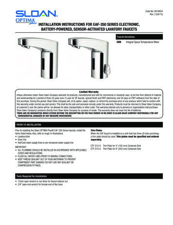
Package ContentsContenido del paquetePlease confirm that all items shown in the image below are included in the packaging.If any parts are missing, please call customer service at 1-800-347-9800.Confirme que todos los artículos que aparecen en la siguiente imagen estén incluidos en elpaquete. Si falta alguna pieza, llame al servicio de atención al cliente al HZJILD4"10"8"12"COLDAATLBBTools Needed: Basin or Crescent Wrench,Slotted and Phillips ScrewdriverCCDDEESx2Herramientas necesarias: Llave ajustable o parainstalar grifos, destornillador para tornillos decabeza ranurada y Phillips25mmParts List* Only included with 1818966, 1818967, 1818968NCOTHO12"AAIL10"8"Placas de recubrimiento opcionalesKHO4"Kfaucet spout A1aeratorB rubber gasketC insulatorD M4 x 12mm screwsE gasketF grounding spacerG mounting nutH sensor washerXZOptional Cover PlatesAYGIJNWFGMXGVLavamanos o mesadaGOptionalT12mmUx2D x2VSink or CountertopDx2BD x2ET12mmCMPBBCCDDEESx225mmLista De PiezasIJKLMNOPrubber washervalve control moduledirt filtermixing valve6" extension hosemain supply line hosedrain ground clampearth ground kitsplit lock washerR nutS M4 x 25mm screwT * thermostatic mixing valveU 12" supply hoseV ground insulation wiresW battery screws and anchorsX “D” cell alkaline batteriesQ2YZAABBCCDDEEdouble-sided foam tapebattery compartmentcover platewashers for cover platecover plate studshex nuts for cover platescrew spacersAPico del grifo A1aerator IArandela de gomaQ Arandela de seguridadY Cinta con adhesivo de ambos ladosBJunta de gomaJMódulo de control de la válvulaR TuercaZ Compartimiento para las bateríasCAisladorKFiltro de suciedadS Tornillo M4 x 25 mmAA Placa de recubrimientoDTornillos M4 x 12 mmLVálvula mezcladoraTEM Manguera de extensión de 15,24 cm (6 in)JuntaEspaciadordeconexiónFN Manguera de tubería desuministro principala tierraG Tuerca de montajeO Sujetador con conexión a tierrade drenajeH Arandela con sensorP Equipo de conexión a tierra* Sólo incluido con 1818966, 1818967, 1818968*Válvula mezcladora termostáticaBB Arandelas para la placa de recubrimientoU Manguera de suministro de 30,48 cm (12 in) CC Pernos de la placa de recubrimientoV Cables de aislamiento de conexión a tierra DD Tuercas hexagonales para la placade recubrimientoW Anclajes y tornillos de las bateríasEE Espaciadores para tornillosX Baterías alcalinas de celda “D”3
Assembly/Ensamble/AssemblageContenu du paquet1Veuillez confirmer que tous les éléments illustrés sur l’image ci-dessous sont contenus dans l’emballage.S’il manque une pièce, veuillez appeler le service clientèle au numéro LDRCOHOTLPlaques-couvercles optionnelleKIBBCCDDEESx2ABec de robinet A1aeratorIRondelle en caoutchoucBJoint en caoutchoucJModule de commande du robinet R ÉcrouCIsolantKFiltre à déchetsS Vis M4 x 25 mmDVis M4 x 12 mmLRobinet mélangeurTEM Tuyau d’extension de 15,3 cmU Tuyau d’alimentation de 30,5 cm CC Goujons pour plaque-couvercleDD Écrous hexagonaux de la plaque-couvercleEntretoise de mise à la terre N Boyau de la ligne d’alimentation V Fils de mise à la terreprincipaleW Vis et fixations de la batterieEE Entretoises pour visÉcrou de montageO Collier de serrage au solX Piles alcalines de type « D »Rondelle du capteurP Kit de prise de terreHQ Rondelle de blocage fendueJoint d’étanchéité*Seulement inclus avec 1818966, 1818967, 1818968BBFG4G25mmListe Des Pièces De RechangeFBBDDOutils nécessaires : Clé pour lavabo ou clé àmolette, tournevis pour vis à fente et tournevisà pointe cruciformeG43JNGuide the semi-assembled faucet spout through the 3-hole4" or 8" center set in counter or sink./Guíe el pico del grifosemiensamblado a través del centro con 3 orificios de 10,16(4 in) u 20,32 cm (8 in) en la mesada o el lavamanos./Orientezle bec de robinet semi-assemblé vers l’entraxe de 10,2 ou20,4 cm à trois trous du comptoir ou lavabo.WFLavabo ou comptoirOptionnelAttach both threaded studs (D) to the bottom of the semiassembled cover plate./Anexe ambos pernos roscados (D) a laparte inferior de la placa de recubrimiento semiensamblada./Fixez les deux goujons filetés (D) au bas de la plaquecouvercle semi-assemblée.Ux2D x2EDT12mmY Isolant adhésif double faceZ Compartiment à pilesAA Plaque-couvercle* Robinet mélangeur thermostatique BB Rondelles pour plaque-couvercleFinish securing the cover plate from underneath by placingthe two metal washers (BB) on to each of the threaded studs.Secure with hex nut (R) and hex nut (DD)./Termine de asegurarla placa de recubrimiento desde abajo colocando las dosarandelas metálicas (BB) en cada uno de los pernos roscados.Asegure con una tuerca hexagonal (R) y una tuerca hexagonal(DD)./Terminez de fixer la plaque-couvercle à partir du bas enplaçant les deux rondelles métalliques (BB) sur chacun desgoujons filetés. Fixez avec l’écrou hexagonal (R) et l’écrouhexagonal (DD).ISecure the spout using the following components in sequential order: Tabgrounding spacer (F) (brass washer on top), brass mounting nut (G), sensorwire connection washer (I). IMPORTANT: Make sure this washer’s tab isrotated 180 from the tab grounding spacer (G), and Brass mounting nut(H)./Asegure el pico utilizando los siguientes elementos en orden secuencial:Espaciador de conexión a tierra con lengüeta (F) (arandela de bronce enla parte superior), tuerca de montaje de bronce (G), arandela de conexióndel cable del sensor (I).IMPORTANTE: Asegúrese de que la lengüeta deesta arandela esté rotada 180 del espaciador de conexión a tierra conlengüeta (G) y la tuerca de montaje de bronce (H)./Fixez le bec en utilisant lescomposants suivants par ordre de séquence : Entretoise de mise à la terrede la patte (F) (rondelle en laiton au dessus), écrou de montage en laiton (G),rondelle de connexion du fil du capteur (I). IMPORTANT : Assurez-vous detourner cette patte de la rondelle à 180 à partir de l’entretoise de mise à laterre de la patte (G), et de l’écrou de montage en laiton (H).5
mblage56VJPILCOLDUHOTU109Connect the earth ground wire (P) to one side of the U-tab.Then connect the yellow sleeved drain ground connector,located on the Grounding Isolation Wires (V), to the otherside of the brass U-tab./Conecte el cable de conexión a tierra(P) a un lado de la lengüeta U. Luego conecte el conector conconexión a tierra de drenaje con funda amarilla, ubicado enlos cables de aislamiento de conexión a tierra (V), al otro ladode la lengüeta U de bronce./Connectez le fil de mise à la terre(P) à un côté de la patte en U. Puis, connectez la cosse demise à la terre de vidange avec gaine jaune, placée sur les filsde mise à la terre (V), à l’autre côté de la patte-U en laiton.Connect the two 12" supply hoses (U) to the mixing valve (L). Placethe rubber washer (I) into the mixing valve’s brass nut fitting (asshown) and then tighten to bottom of the valve control module (J)./Conecte las dos mangueras de suministro de 30,48 cm (12 in) (U)a la válvula mezcladora (L). Coloque la arandela de goma (I) enel acople de la tuerca de bronce de la válvula mezcladora (comose muestra) y luego ajuste hacia la parte inferior del módulo decontrol de la válvula (J)./Connectez les deux tuyaux d’alimentationde 30,5 cm (U) au robinet mélangeur (L). Placez la rondelleen caoutchouc (I) dans le raccord à écrou en laiton du robinetmélangeur (tel qu’indiqué), puis serrez jusqu’au bas du module decommande du robinet (J).87Connect the longer green earth ground wire to the clamp tab./Conecte el cable de conexión a tierra verde más largo a lalengüeta del sujetador./Connectez le long fil de mise à la terrevert sur la patte pour collier.Mount the drain ground clamp to the metal drain tail stockas close to the sink as possible./Coloque el sujetador conconexión a tierra de drenaje en el cabezal móvil de drenajemetálico lo más cerca del lavamanos posible./Montez le collierde mise à la terre de vidange sur la contre-poupée de vidangemétallique aussi proche du lavabo que possible.1112RVOQVHand tighten the valve control module assembly to the faucetshank. NOTE: Make sure the black rubber washer is in thewhite plastic nut before connecting the valve control moduleto the faucet shank./Ajuste con la mano el ensamble delmódulo de control de la válvula al cuerpo del grifo. NOTA:Asegúrese de que la arandela de goma negra se encuentreen la tuerca de plástico blanca antes de conectar el módulode control de la válvula al cuerpo del grifo./Serrez à la mainl’assemblage du module de commande du robinet sur la tigedu robinet. REMARQUE : Assurez-vous que la rondelle encaoutchouc noire se trouve dans l’écrou en plastique blancavant de connecter le module de commande du robinet à latige du robinet.Mount the earth ground clamp to the cold water supply pipe./Coloque el sujetador con conexión a tierra en la tubería desuministro de agua fría./Montez le collier de mise à la terresur le tuyau d’alimentation en eau froide.6DDConnect the brass plated end (black sleeved) of the greenGrounding Isolation Wires (V) to the drain ground clamp tab(O)./Conecte el extremo enchapado en bronce (con fundanegra) de los cables de aislamiento de conexión a tierraverdes (V) a la lengüeta del sujetador con conexión a tierrade drenaje (O)./Connectez l’extrémité plaquée en laiton (avecgaine noire) des fils de mise à la terre (V) sur la patte pourcollier de mise à la terre de vidange (O).Connect the ring terminal on the green Grounding Isolation Wires (V)to the stud with the hex nut (R). Continue fastening with lock washer(Q) and hex nut (DD). NOTE: For single-hole mounted faucets removethe ring terminal wire with wire cutters./Conecte el terminal anilloen los cables de aislamiento de conexión a tierra verdes (V) al pernocon la tuerca hexagonal (R). Continúe ajustando con una arandelade seguridad (Q) y una tuerca hexagonal (DD). NOTA: Para los grifosmontados de un solo orificio extraiga el cable del terminal anillo conalicates./Connectez le terminal de l’anneau placé sur les fils de miseà la terre verts (V) au goujon avec l’écrou hexagonal (R). Continuezde fixer avec la rondelle de blocage (Q) et l’écrou hexagonal (DD).REMARQUE : Pour les robinets montés sur un seul trou, retirez le fildu terminal de l’anneau avec des tenailles coupe-fils.7
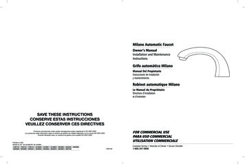
Assembly Schematic/ Esquema de ensamble/Schéma de PORTANT: All wires MUST BEconnected as shown.IMPORTANTE: DEBEN conectarsetodos los cables como se muestra.IMPORTANT : Tous les fils DOIVENTÊTRE connectés tel qu’indiqué.NOTE: Above counter partscome pre-assembled.NOTA: Las piezas que van sobre lamesada vienen preensambladas.REMARQUE : Les pièces du comptoirsont préassemblées.ABSCVIZJManual Override DialSelector de apagado manualCadran d’arrêt manuel(gr(ve een)(ver rde)t)KIMPORTANT: Must have tightconnection around drain.IMPORTANTE: Debe teneruna conexión fuerte alrededordel drenaje.IMPORTANT : Il doit y avoir uneconnexion étanche autour dela vidange.Earth Ground WireCable de conexión a tierraFil de mise à la terreILDCOULAerators are available in additional sizes (1.5 gpm & 2.0 gpm) forpurchase, if you desire to increase water flow. To install the newaerator, remove the existing aerator by hand. If the aerator is tootight to be removed by hand, it is recommended that a strap wrenchbe used to loosen it. Once the old aerator has been removed, thenew aerator can be installed and hand-tightened in its place.8(gr(ve een)(ver rde)t)IMPORTANT: Must have tightconnection to metal supply line.IMPORTANTE: Debe tener unaconexión fuerte a la línea desuministro metálica.IMPORTANT : Il doit y avoir uneconnexion étanche à la conduited’alimentation métallique.PKConnect the black sensor wire to the sensor washer (H)./Conecte el cable del sensor negro a la arandela delsensor (H)./Connectez le fil du capteur noir à la rondelle ducapteur (H).Black Sensor WireCable del sensor negroFil du capteur noirRed IndicatorIndicador rojoIndicateur rougeDrain Ground WireCable con conexión a tierra de drenajeFil de terre de vidangeattach to drainAnexo al drenajeFixez-le à la vidangeHGT15DDGHCCQHOSee battery compartment installation instructions on page 10.Then connect the battery power connector wires together. Test theblack sensor wire with your fingers. There will be a clicking soundcoming from the valve control module indicating that the faucetis installed properly./Consulte las instrucciones de instalación delcompartimiento para las baterías a continuación (pg. 10). Luegoconecte juntos los cables del conector de alimentación de lasbaterías. Pruebe el cable del sensor negro con los dedos. Escucharáun chasquido proveniente del módulo de control de la válvula queindica que el grifo está instalado adecuadamente./Voir les directivesd’installation du compartiment à piles ci-dessous (pg. 11). Puis,connectez les fils du connecteur d’alimentation par pile. Testez le fildu capteur noir avec vos doigts. Le module de commande du robinetproduira un cliquetis pour indiquer que le robinet est bien installé.FR(green)(verde)(vert)Connect the other end of the green Grounding Isolation Wires(V) to the tab grounding spacer (F)./Conecte el otro extremode los cables de aislamiento de conexión a tierra verdes (V) alespaciador con conexión a tierra con lengüeta (F)./Connectezl’autre extrémité des fils de mise à la terre (V) à l’entretoise demise à la terre de la patte (F).BBEEEAAIMPORTANT: All wires MUST BEconnected as shown.IMPORTANTE: DEBEN conectarsetodos los cables como se muestra.IMPORTANT : Tous les fils DOIVENTÊTRE connectés tel qu’indiqué.9
Battery Compartment InstallationInstalación del compartimientopara las bateríasInstallation du compartimentà piles 1. R emove battery compartment cover by unscrewing thetwo Phillips screws. Inside the battery compartment(Z) there are two large screws and anchors (W). Placethe battery compartment (Z) in a convenient locationensuring easy access. 1. Extraiga la cubierta del compartimiento para lasbaterías desatornillando los dos tornillos Phillips.Dentro del compartimiento para las baterías (Z)hay dos anclajes y tornillos grandes (W). Coloqueel compartimiento para las baterías (Z) en un lugarpráctico para garantizar un fácil acceso. 1. R etirez le couvercle du compartiment à piles endévissant les deux vis cruciformes. Deux grandesvis et fixations (W) sont contenues à l’intérieur ducompartiment à piles (Z). Placez le compartiment à piles(Z) dans un emplacement convenable et facile d’accès.2. S ecure to wall using screws and anchors (W) or double-2. A segúrelo a la pared utilizando anclajes y tornillos (W)sided tape (Y).o cinta con adhesivo de ambos lados (Y).3. I nstall four (4) “D” cell alkaline batteries (X). Replacecover on battery compartment. Connect battery boxconnector to valve power connector. Once power isestablished, you will hear a clicking sound when youplace your hand under the faucet.3. I nstale las cuatro (4) baterías alcalinas de celda “D”(X). Vuelva a colocar la cubierta en el compartimientopara las baterías. Conecte el conector de la caja parabaterías al conector de alimentación de la válvula. Unavez que se conecte a la alimentación, escuchará unchasquido cuando coloque la mano debajo del grifo.4. T urn water supply on. The water will automaticallycome on when you place your hand under the faucet.The water will stay on for a maximum of 15 seconds aslong as your hands are under the faucet, and moving.The water will shut off after you remove your handsfrom the sensing zone or water stream.4. A bra el suministro de agua. El agua saldráautomáticamente cuando coloque la mano debajo delgrifo. El agua seguirá saliendo durante un máximode 15 segundos siempre que deje las manos debajodel grifo y las mueva. El agua se cortará después deque retire las manos de la zona del sensor o chorro deagua.5. V erify water supply connections are not leaking.5. V erifique que las conexiones de suministro de agua noSetting Water Temperature Mix2. F ixez-le au mur à l’aide des vis et fixations (W) ou de labande double face (Y).3. I nstallez quatre (4) piles alcalines de type « D » (X).Replacez le couvercle sur le compartiment à piles.Branchez le connecteur du boîtier à piles au connecteurd’alimentation du robinet. Une fois l’appareil soustension, vous entendrez un cliquetis lorsque vousplacerez la main sous le robinet.4. R établissez l’alimentation en eau. L’eau couleraautomatiquement lorsque vous placerez la main sousle robinet. L’eau continuera de couler pendant au plus15 secondes tant que vos mains seront sous le robinet.L’eau s’arrêtera de couler dès que vous retirerez vosmains de la zone de détection ou du flot d’eau.5. V érifiez que les raccords de l’alimentation en eau nefuient pas.tengan pérdidas.1. T here is a temperature dial on the mixing valve (L). Usea screwdriver to loosen the screw on the dial. To addhot water, turn the knob to the right or to the left toadd cold water.Ajuste de la mezcla detemperatura de agua2. O nce you have the desired water mix temperature, lockthe control knob in place with a screwdriver.1. Hay un selector de temperatura en la válvulamezcladora (L). Utilice un destornillador para aflojar eltornillo del selector. Para agregar agua caliente, girela perilla hacia la derecha o hacia la izquierda paraagregar agua fría.3. T here is a temperature adjustment on the optionalthermostatic mixing valve (T). Use an allen wrench toturn adjustment screw to add hot or cold water.2. Una vez que obtenga la temperatura de la mezcla deagua deseada, fije la perilla de control en el lugar conun destornillador.3. Hay un ajuste de temperatura en la válvula mezcladoratermostática opcional (T). Utilice una llave allen paragirar el tornillo de ajuste para agregar agua caliente ofría.10Réglage du mélange detempérature de l’eau1. L e robinet mélangeur (L) comporte un cadran deréglage de la température. Utilisez un tournevis pourdesserrer la vis du cadran. Pour ajouter de l’eauchaude, tournez le bouton vers la droite et vers lagauche pour ajouter de l’eau froide.2. U ne fois que vous avez la température de mélanged’eau désirée, verrouillez le bouton de commande àl’aide d’un tournevis.3. L e robinet mélangeur thermostatique optionnel (T)comporte un réglage de température. Utilisez uneclé hexagonale pour tourner la vis de réglage afind’ajouter de l’eau chaude ou froide.11
TroubleshootingProblemSolución de l issues due todrain pipe obstructionsDrain pipe or otherplumbing under the sink orcountertop is in the way.Use the optional flexible 6" extension hose (M). It is to be placed between the spout shank (A) and the outlet ofthe valve control module (J). The faucet components can then be assembled off to one side of the drain or otherplumbing. Do not add any plumbing or piping components not Included in this kit to the faucet installation as itmay cause the faucet to not function or sense properly.Problemas deinstalación debido aobstrucciones en eltubo de desagüeEl tubo de drenaje u otratubería debajo del lavamanoso la mesada está estorbando.Utilice la manguera de extensión de 15,24 cm (6 in) flexible opcional (M). Debe colocarse entre el cuerpo del pico(A) y la salida del módulo de control de la válvula (J). Así, los componentes del grifo pueden desensamblarse haciaun lado del tubo u otra tubería. No agregue ningún componente de tubería o cañería que no esté incluido en esteequipo en la instalación del grifo ya que podría hacer que el grifo o el sensor no funcionen adecuadamente.Faucet not working(No flashing red LEDlocated o n valvecontrol module)Batteries not insertedcorrectlyRemove cover from battery box (Z) check that the batteries (X) have been inserted to the correct orientation andare making connection to the contacts. Refer to the battery icons located on the base of the battery box tray.El grifo no funciona(No parpadea el LEDrojo ubicado en elmódulo de controlde la válvula)Las baterías no se colocaroncorrectamenteExtraiga la cubierta de la caja para baterías (Z), verifique que las baterías (X) se hayan colocado en la orientacióncorrecta y estén haciendo contacto. Observe los íconos de las baterías ubicados en la base de la caja para baterías.Faucet not workingand no water flowswhen activated(Red LED is flashing)Intermittent cyclingand/or water runs onafter actuationImproper or poorconnection to power supplyLow batteriesCheck that the connection from the battery box is fully inserted into the female connector on the valve controlmodule (J) and assure the connector round thumbnut is fully fastened.If red indicator is flashing 5 times every 4 seconds, replace with new Alkaline batteries (X).Water source valves turnedoffOpen water source valves and check that there is water flow.Sensor shorted to ground orunit unable to calibrateIf red indicator is flashing once or multiple times every 4 seconds, there is a problem with the installation and thesensor is shorted. To verify the valve control module is working correctly, carefully disconnect the black sensor wirefrom the connection washer (H). With the wire disconnected, touch the connector at the end of the black wire withyour fingers. The sensor should activate and water should come on. Let go of the connector and the water shouldshut off. If the unit works as described above, it malfunctions when you reconnect the black sensor wire to thespout assembly, then there is an error in the spout and cover plate installation. If the faucet does not activate asdescribed when touching the sensor connector, then you have a grounding issue or there is a broken sensor wire(see troubleshooting below).Improper groundconnectionIf you can touch any of the steel braided supply hoses, the brass fitting on the valve control module, or the mixingvalve and it activates the unit, there is improper earth grounding (P). Verify that the ground clamp (P) has beeninstalled and recheck the connections. Verify the clamp is tightly fastened directly to the copper pipe for a properground connection. Disconnect power source for 10 seconds. The valve will close and the water will stop running.After 10 seconds, reconnect power supply. Let unit recalibrate for another 20 seconds and verify faucet activation.Broken or corrupt sensorwire or defective valvecontrol module electronics.If the connector has broken off of the black sensor wire or the valve control module appears to be defective pleasecontact Technical Concepts. Do not attempt to repair the valve control module (J) or sensor wire.Poor sensor washer and wire connectionVerify the brass nuts (G) that fasten the connection washer (H) are fully tightened. Reconnect the sensor wire to thewasher. Reset unit following the procedure below.*Insufficient groundconnectionVerify that the earth ground clamp (P) has been installed and recheck the connections. Verify the clamp is tightlyfastened directly to the copper pipe for a robust ground connection. Reset unit following the procedure below.*SST faucet components arein contact with metal partsof the sink or plumbing.Be sure that all of the SST faucet components (cover plate, white plastic screw spacers, brass shank, metal washer,braided hoses) or any components for the sink (metal sink lip/mounting hardware) or countertop (i.e. metalsupport brackets/structural parts) are not in contact and are spaced from each other. Reset unit following theprocedure below.*Intermittent cyclingand /or faucetactuation is overlysensitiveIsolation parts are notinstalled or not installedcorrectly.If you can touch the sink and the faucet activates, the unit installation is improper. Check that isolationcomponents (C, EE, & F) are used and installed correctly. If the sink is of a metal composition, verify the sinkground connection (V) is in place and installed properly.Faucet doesn’t shutoff after you pullyour hands awayDrain grounding notconnected or assembled.Check that the drain ground (O) is assembled to the threaded portion of the metal drain ring (not on thepipe) and is connected to the tab on the valve control module (J). Reset unit following the procedure below.*Water stays onThere is sensor short toground or unit is notcalibrating.Reset unit following the procedure below.* The valve should close and the water will stop running. Let unitrecalibrate for 20 seconds and verify faucet activation. If water continues to run, then there is an error in theinstallation and grounding scheme (see troubleshooting above).Dial set to the “open”position or not turned tothe full “auto” positionTurn the knob on the side of the valve control module (J) fully to the “auto” position (until it hits the stop)and actuate the faucet by placing your hand near the spout. Water should stop running and unit will returnto the normal idle operation mode when you remove your hand from the spout.Debris or particulatematter is trapped in valveTurn off water source valves. Remove aerator from end of the spout (A) and examine for dirt and particulates.Inspect and clean input dirt filter (K). Reinsert filter and turn water source back on. Actuate faucet severaltimes without the aerator installed to flush any debris from the valve mechanism until dripping has ceased.Reinstall aerator.Dial not turned to the full“auto” positionTurn the knob on the side of the valve control module (J) fully to the “auto” position (until it hits the stop)and actuate the faucet several times by placing your hand near the spout. Water should stop running ordripping and unit will return to the normal idle operation mode once you remove your hand from the spout.Increase or decreasewater flowSize of aerator or watersupply flowFirst check that the water supply line valves are fully open and the lines are not restricted. If water flow is notas desired, optional sized aerators to control water flow (1.5 & 2.0 GPM) can be purchased.Water temperaturetoo hot or coldNo mixing valve installedor mixing valve needsadjustmentInstall a mixing valve (L). Adjustments can be made to the valve by resetting the temperature control knob.If more precise or anti scald water temperature control is required, the optional thermostatic control valve (T)may need to be purchased.Flushing faucet for regulatory protocolRequired hygiene or sanitary procedureTurn the knob on the side of the valve control module (J) to the “open” position to flush faucet. This is amechanical override of the automatic sensing and will set the valve to a constant open position. Once thewater is flushed as required, turn the knob back fully to the “auto” position (until it hits the stop) and ceasewater flow by placing hand near faucet and pulling hand away.Leaky faucet* How to reset unit: Disconnect power source for 10 seconds. Valve will close and water will stop running. After 10 seconds, reconnect power supply. Let unit recalibratefor another 20 seconds. Verify faucet activation.12El grifo no funcionay no sale aguacuando se activa(El LEDrojo parpadea)Ciclo intermitenteo agua que siguesaliendo despuésdel accionamientoConexión inadecuada odeficiente al suministro dealimentaciónBaterías agotadasLas válvulas de la fuente deagua están cerradasVerifique que la conexión de la caja para baterías esté completamente insertada dentro del conector hembraen el módulo de control de la válvula (J) y asegúrese de que el conector alrededor de la tuerca mariposa estecompletamente ajustado.Si el indicador rojo parpadea 5 veces cada 4 segundos, coloque nuevas baterías alcalinas (X).Abra las válvulas de la fuente de agua y verifique que salga agua.El sensor está en cortocircuitoa tierra o la unidad no puedecalibrarseSi el indicador rojo parpadea una o varias veces cada 4 segundos, hay un problema con la instalación y el sensor estáen cortocircuito. Para verificar que el módulo de control de la válvula esté funcionando correctamente, desconectecuidadosamente el cable del sensor negro de la arandela de conexión (H). Con el cable desconectado, toque elconector en el extremo del cable negro con los dedos. Debería activarse el sensor y salir agua. Suelte el conector y elagua debería cortarse. Si la unidad funciona como se describe anteriormente, funciona mal cuando vuelve a conectarel cable del sensor negro al ensamble del pico, entonces hay un error en la instalación de la placa de recubrimientoy el pico. Si el grifo no se activa como se describe cuando toca el conector del sensor, entonces tiene un problema deconexión a tierra o hay un cable del sensor dañado (vea solución de problemas a continuación).Conexión a tierra inadecuadaSi puede tocar cualquiera de las mangueras de suministro con malla trenzada de acero, el acople de bronce enel módulo de control de la válvula o la válvula mezcladora y esto activa la unidad, hay una conexión a tierrainadecuada (P). Verifique que el sujetador con conexión a tierra (P) haya sido instalado y vuelva a controlar lasconexiones. Verifique que el sujetador esté fuertemente ajustado directamente al tubo de cobre para lograr unaconexión a tierra adecuada. D
Installation and Maintenance Instructions Grifo automático Milano Manual Del Propietario Instrucciones de instalación y mantenimiento Robinet automatique Milano Le Manuel du Propriétaire Directives d'installation et d'entretien Customer Service Atención al Cliente Service Clientèle 1-800-347-9800 FOR COMMERCIAL USE PARA USO .