Transcription
Uses and Misuses of Duct Board:Understanding the NewHigh-Performance MaterialsBrad Oberg, AIAABSTRACTThis paper is based on a white paper developed at the author’s firm, which discusses the appropriate uses for fibrous glassduct board for residential HVAC applications. Here the author describes the characteristics and benefits of fibrous glass ductboard and addresses issues specific to fibrous glass duct construction, including the concern that fiberglass ducts collect waterand support growth of mold.INTRODUCTIONHigh-performance homes inherently have green characteristics because, when appropriately engineered, they use lessmaterial, consume less energy, and are more durable, comfortable, and safe. Because duct board already has thermal insulation and does not require additional external insulation asmetal duct does, it provides a good option for developing ductsystems for high-performance homes. However, there hasbeen resistance to the use of duct board in residential applications due to concerns about moisture retention and moldgrowth. Uncoated or unfaced duct board has high moistureabsorbing potential and a large amount of fiber surface areathat increases surface friction, but newer generation productsthat include a matte coating or laminated facing on the insideface of the board reduce these negative characteristics.Why is an engineered duct system that incorporates highquality products important to system and home performance?Homes built to code require heating and cooling air capacitiesas high as 1 cfm per square foot of floor area. With evenmoderate influence of newer codes, and the introduction ofbetter window systems, double glazing, and low-emmisivitycoatings, a home built to code can use as little as 0.4 cfm persquare foot of floor area. Homes built to Energy Star levels,or meeting state energy codes such as California Title 24, orthose in Wisconsin, New York, and Florida, can require aslittle as 0.2 cfm of air delivery per square foot of floor area.These reduced airflow demands allow the use of smallerducts but also reduce the margin for error in duct installation.Critical performance needs of the distribution system areairtightness and an engineered environment with predictableperformance characteristics. Sheet metal ducts are a consistentengineering material with well-documented flow characteristics; however, they are difficult to adequately seal, requireadditional insulation, and are not easily fabricated in the field.Flexible duct materials are pre-insulated and, with care, can besealed adequately but are inconsistent in flow characteristicsbecause of inconsistent care in installation. Duct board trunksand large branches may be field- or shop-fabricated to createpre-insulated airtight duct sections with consistent andpredictable flow characteristics.QUALITY AND PERFORMANCECHANGES IN CURRENT PRODUCTSThe latest generation of duct boards are semi-structuralinsulated fibrous glass boards, with a vapor retarder facing onthe exterior and a laminated matte liner in the interior, providing a smooth cleanable airstream face on the air side. In recentyears, all of the major duct board producers have added coatedor laminated products to their lines, while maintaining theBrad Oberg is the co-founder and chief technology officer of IBACOS, Inc., Pittsburgh, Pa. 2004 ASHRAE.
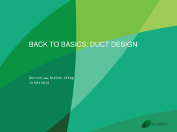
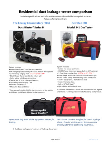
basic duct board products. Fibrous glass ducts now provide anengineered air delivery environment with predictable designcharacteristics of structure, pressures, friction, and thermalproperties.KEY CRITERIA FOR SELECTING ADUCT CONSTRUCTION METHODPhysical Strength: Self-Supporting Structureand High Overpressure CapacityThe following test results have been documented in the“Fibrous Glass HVAC Duct Systems: Proven Performance”report by North American Insulation Manufacturers Association (NAIMA 1996). The tests were performed by NAIMAusing Underwriters’ Laboratories’ (UL) test procedures forstructural integrity, where duct samples were subjected to avariety of tests. Based on test data, fibrous glass duct board isa strong and durable material system.In one test procedure where a duct sample is subjected tothe impact of a two-pound rod dropped in several locations,including joints, fibrous glass duct was found to be punctureresistant. In another test, a duct span was subjected to staticload. The test result was that the structural integrity of fibrousglass duct exceeds that required in actual installations. In athird test, where sealed duct sections are subjected to 2.5 timesrated positive and negative pressures, fibrous glass ductssuccessfully withstood positive and negative test pressure 2.5times higher than rated operating pressures. This surpasses the50% margin required in most installations.are less rough. When sizing fibrous glass duct board, themanufacturer’s literature and design criteria should always beconsulted. IBACOS has created a set of friction curves that weuse to design the duct systems. These three curves are shownin Figure 1. The blue curve is the sheet metal curve, the greencurve is that of unfaced or finished duct board, and the yellowis our best estimate of the design values for the laminate-facednew generation duct board product. Sheet metal friction isbased on surface and joint configurations. The uncoated ductboard, classified as a medium roughness, is controlled by highersurface friction. The faced/coated duct board behaves onlyslightly rougher than sheet metal but does not have joint interruptions, so we estimated it as overall slightly 5% rougher.Installation and FittingsFibrous glass duct board may be used in a variety of residential purposes. It can be used in applications ranging fromstraight duct sections, elbows, and tees, to offsets and othersystem elements. There are some specific areas within the ductsystem where fibrous glass duct board may not always be therecommended product because of the high potential for exposure to water. These applications will be discussed in detail inthe “Issues Specific to Fibrous Glass Duct Construction”section. Also, fibrous glass duct board should not be used inconcrete, buried below grade, or any other location where itmay be directly exposed to weather or physical abuse.Fibrous duct construction should conform to the SheetMetal and Air Conditioning Contractors' National Association(SMACNA) Fibrous Glass Duct Construction Standards orNAIMA Fibrous Glass Duct Construction Standards andinclude predictable cross sections and transitions, as well astraditional take-offs and pressure regain regions.Installation of the supply trunk and main return duct aredone using straight duct modules fabricated from flat sectionsof fibrous glass duct board. Joints and longitudinal seams needto be sealed using a UL 181 approved closure system, asoutlined in NAIMA’S Fibrous Glass Duct Construction Standards, 2nd edition (NAIMA 1997). Fibrous glass ducts arelight and can be supported with a typical number of hangers,again following SMACNA or NAIMA standards.Attachment of insulated flex duct to fibrous glass ducts isas simple as spinning in a collar, sealing the pressure liner, andsecuring the vapor-retarding covering to the facing of thefibrous glass duct board.When building elbows or installing volume or zoningdampers, adequate support must be provided. Exterior bracingsections may be added, or short sections of metal frame maybe inserted inside the duct. All but heavy accessories may besupported within the fibrous glass duct board sections. Theseaccessories can still be used with fibrous glass duct board butwill simply need to be independently supported, as is the casewith all duct material. Turning vanes and duct offsets areachieved without added bracing.Pressure Loss and SizingCondensation ControlWhen sizing fibrous glass duct board systems, there aretwo key considerations. First, make sure that the fabricationdrawings clearly state interior dimensions, as many new fabricators will measure to the outside and have restricted flow.Second, design the ducts for the appropriate friction rate associated with the material specified. The new duct boards allhave a facing and have significantly reduced the friction of theair side finish of the duct board.Standard uncoated fibrous glass duct board is classified asa medium-rough surface by ASHRAE (2001), while laminated and coated fibrous glass duct boards have surfaces thatIn insulated duct systems, condensation on the surface ofthe ductwork is a concern during the cooling and heatingseasons. The inherent attributes of ductwork constructed offibrous glass duct board provide solutions to these conditions:System Application21.During heating mode, the air inside the ductwork is hot anddry with little potential for condensation on the backside ofthe exterior surface. In northern attics, additional insulationshould be considered outside the duct board structure itself,equal to the insulation value of the duct board. If the ductserves cooling only, the ducts should be sealed duringwinter operation to minimize condensation.Buildings IX
Figure 1 Duct material friction comparison.2.When ductwork is located in an unconditioned space duringheating mode, all of the energy is focused on drying, andthere is little potential for condensation except in far northern climates. Additional insulation outside the duct boardwill be needed if interior RH is maintained at levels exceeding 50%, or where ducts are used only for cooling, and airis not circulated through the ducts in the winter.3.During cooling mode, condensation potential from the interior is limited because the saturated air exiting the coolingcoil increases in temperature, which increases the capacityto hold moisture and the relative humidity drops, againlimiting the potential for condensation.4.When ductwork is located in an unconditioned space duringcooling mode, an adequate thickness of insulation willprevent the cold interior air from lowering the exteriorsurface of the fibrous glass duct board to a temperature suitable for condensation. This is the one mode where condensation can occur on the exterior of the ducts, and similarperformance can be seen in fibrous glass duct board as wellas insulated sheet metal ducts. Humid attic air will condenseon cold surfaces. Increasing the insulation levels will raisethe exterior surface temperature, reducing condensation.Southern homes in hot and humid environments with atticsthat are vented to exterior humid conditions may need to usean R-8.5 insulation level, accomplished by fabricating withBuildings IXthicker duct board, not to conserve cooling energy, but tocontrol condensation. If the attics are not vented then thedew point will be closer to the conditioned space and additional insulation will not be needed.Mold Growth PotentialAccording to NAIMA (1996) studies, it has been incorrectly thought that microbes will use the resin bonding and theglass fibers in fibrous glass duct board as a food source tosupport mold growth. Further, the glass fibers that make up thecore of fibrous glass duct board are inorganic and, therefore,do not support mold growth. Many fibrous glass duct boardsare now produced with antimicrobial agents integrated into thesurface to act as a preventive agent against the growth of moldon the airstream surface. In fact, the dust that accumulates inductwork during normal system operation provides the foodsource to support mold growth. Fibrous glass duct board haspassed the UL 181 tests for long-term durability. Using the ULtest procedure, duct samples containing mold mycelia andbread spores were placed in a dark chamber with high humidity for 60 days. The test result confirmed that fibrous glass ductinsulations do not support microbial growth.Mold growth studies conducted by researchers Thomannand Tulis (1996) show that mold growth is not surface specific.Under similar conditions of temperature, water, and food(dust) availability, both fibrous glass duct board and galva3
nized metal ducts showed equal mold growth. Studies haveshown that the presence of available water and food (dust)becomes the determining factor to mold growth, not the typeof duct material. Researchers found that fungal growth wasrarely observed on many different duct surfaces subjected tohigh-humidity air, even when exposed over extended periodsof time. In contrast, fungal amplification was regularlyobserved where liquid water was introduced to the ductsurfaces. Therefore, wherever liquid water was introduced tothe system, microbial growth was observed on all surfacetypes of ducts, including circular metal “flex” duct, the flatsurfaces of metal ducts, plastic-lined flex duct, caulks andsealant, conditioning coils, metal sound attenuators, and internal duct liners.Thomann and Tulis (1996) conclude that incidents ofmold growth in ducts are not a duct material issue, but, rather,an operation and maintenance issue of the space conditioningsystem. Because eliminating all dust from the equation isimpossible, it is imperative that the system be properlydesigned to eliminate water.Operation of the HVAC systems may create conditionsthat are suitable for mold growth on any duct material. HVACducts fabricated from all types of materials will becomecontaminated with dust and dirt from normal system operation. Air carrying dust is continually returned through thesystem and filtration systems. Even when properly maintained, HVAC and filtration systems do not stop all of this dusttransfer from occurring. This dust will continually travelthrough the HVAC unit and the ductwork and will be depositedthroughout the systems. Dust and dirt collect in areas of roughness. Unfaced duct board, poorly fabricated joints betweenduct sections of any materials, and areas of low pressure foundwith abrupt increase or decrease in size will collect more dirtthan smooth well-fabricated ducts. This dust and dirt providesthe food source for mold growth when combined with water.For this reason, it is essential that HVAC systems be designedand fabricated with care and that ductwork be inspected yearlyand cleaned as needed.LeakageAccording to the International Code Council (ICC 2000),all joints and seams should be made airtight by means of anapproved closure system. Closure systems used with rigidfibrous glass duct systems should comply with UL 181A.Leakage of conditioned air out of supply ducts or nonconditioned air into return ducts can severely compromise theoverall energy efficiency of an HVAC system. Fibrous glassduct systems, when installed according to manufacturer’srecommendations, have minimal leakage. In a NAIMA testusing a UL test procedure (NAIMA 1996), a flow metermeasured leakage under positive pressure in an eight-footfibrous glass duct section with both ends capped. A test wasconducted on duct samples already exposed to static load,impact, pressure, or collapse tests. The result was that leakagein fibrous glass ducts does not exceed 20 times the static4volume of the duct in a one-hour period, the maximum permitted by the UL standard.The fact that the trunks and continuous sections of ductcan be made tight does not eliminate the need to properly fabricate connections and transitions. Metal collars should be aspin-in type, designed for fibrous glass ductwork, and thecollar should be sealed with mastic to the facing of the ductboard. Duct board sections are fabricated into full crosssections and are tested to two-and-a-half times the rated operating pressure of 2 in. w.c. (498 Pa). In overpressure, the sealmay not slip, and, in underpressure, the cross section may notcollapse more than 20% of the cross section.Acoustic PerformanceNoise in ductwork is created by the furnace blower, theblower turbulence, mechanical noise, and blower and motorvibration, as well as from the turbulence that is created fromthe movement of air through the ductwork. The attributes offibrous glass duct board reduce these noises more than sheetmetal when common design techniques are used. (Sheet metalcan regenerate or amplify the noise and transmits vibration tothe house structure via hangers and other contact points.)Based on NAIMA (2002) studies, fibrous glass duct boardreduces the noise associated with the blower, as well as the airturbulence within the duct. Also, fibrous glass duct board doesnot create duct noise by popping or booming due to expansionand contraction. It also helps to reduce room-to-room noisetransfer.CleaningAs NAIMA (1998) reports, fibrous glass duct board maybe cleaned with conventional methods. The three most popularmethods are air sweeping, vacuuming, and rotary brush. Neveruse steam or any cleaning method that involves water to cleanfibrous glass duct board. With air sweeping, a nozzle isinserted into the duct, and the accumulated dust is lifted by acompressed airstream and carried away by a general flow ofair induced by a vacuum downstream. Contact cleaning isachieved by a vacuum cleaner with a low stiffness brush usedto vacuum the inside surface of the duct. With a low stiffnessrotary brush, a powered head is inserted into the duct with longbristles that lift the dirt by direct impact on the surface.The concern about duct cleaning is the issue of fibererosion. However, the only aggressive method is the rotarybrush, where poor attention may allow the brush to stay in onelocation too long and damage the surface. The newest generation of internally faced products addresses this concern, butalso ensuring that the brush is kept moving and using a softerwhisker brush would eliminate these issues, according toNAIMA (1998).Access to the duct for cleaning is achieved by using aknife to cut access panels into the fibrous glass duct board.There are several different ways to cut these accesses, and eachcut piece can easily be replaced and sealed back into the ductafter the cleaning is complete. Guidelines are available fromBuildings IX
the “NAIMA Cleaning Fibrous Glass Insulated Air DuctSystems Recommended Practice” brochure (NAIMA 1998).If adequate care is given to keeping ductwork clean duringthe construction process, fibrous glass duct board should notneed initial cleaning. For off-site fabrication, it is importantthat the fibrous glass duct board be swept out after fabricationto remove any loose fibers that may be left inside the duct fromcutting the fibrous glass duct board. Care should be takenduring transportation of the duct fabricated off-site to keep itclean and free of contaminants. It is essential that the ducts beprotected and kept dry during transit so as to prevent moistureentering the duct system prior to its installation. If the fibrousglass duct board is fabricated on the job site, it will also needto be properly cleaned out prior to it being installed. The additional challenge of on-site fabrication is that the work areamust be kept clean and dry throughout the process. This issometimes difficult on a construction site, but it is essential forensuring that the integrity of the fibrous glass duct board bemaintained prior to its installation.For condensation control according to NAIMA (1996),the fibrous glass duct’s outer jacket acts as a vapor retarder tohelp control moisture condensation in the air-handling system,thus reducing the opportunity for water damage or for microbial growth and amplification.ISSUES SPECIFIC TO FIBROUSGLASS DUCT CONSTRUCTIONOne of the concerns with fibrous glass duct board is itsinterior surface. Its interior composition of glass fibers isrough when compared to smooth steel and has caused manyindustry contractors to question whether fibrous glass ductboard is a safe and durable option. Testing using UL test procedures, however, has proven that fibrous glass duct board is asafe and durable duct fabrication material. Discussed beloware issues specific to fibrous glass duct construction, as well astesting results and industry research that address theseconcerns. This section also discusses, in particular, horizontalair-handling units, downflow systems, and bottom returnsystems, which require careful attention in installation.material construction and result in similar wetting of bothmetal and fibrous glass ducts:1.Improper sizing of the cooling coil. When the cooling coilis undersized, when compared to the furnace, it reduces thefree area and increases the velocity of the air as it goesthrough the coil. This condition creates the potential forblow-off.2.Restriction of airflow, allowing buildup of ice on the coil.This can occur with an improperly sized cooling coil and/orrestrictive ductwork in the plenum. These conditionsrestrict airflow across the cooling coil. When the coolingcoil does not have adequate airflow across it, it becomes toocold, and ice buildup occurs.3.Restriction in free area of the coil due to dirt buildup onthe coil surface. This results from lack of proper maintenance on the system over time, allowing dirt to build up andreduce free area. This reduction of free area createsincreased velocities and potential for ice buildup.4.Air bypassing the coil, picking up water from a poorlydrained condensate pan. When the coil is restricted, particularly in horizontal flow units, the air is delivered past thecoil and picks water up from the pan. In severe conditions,the pan simply overflows.Wetting of duct surfaces in the return plenum of upflowsystems can also be a problem. Many styles of air-handlingunits have supplied return air either through the sides of the fansection or through the bottom of the unit, such as when the unitis set over a return box plenum. Wetting of these plenumsdirectly below the air-handling unit occurs in several ways.1.After a cooling cycle, cool air drops off the coil above andchills surfaces. In poorly sealed ductwork, humid exteriorair can be introduced and cause some condensation. Thesolution is to use sealed ductwork on both supply and returnand to build in a vapor retarder and insulation to isolate thecool interior from a moist exterior. Fibrous glass duct boarddoes this as an inherent aspect, while metal duct requires theaddition of well-executed insulation and vapor retarderapplication. The use of framing materials and gypsum wallboard should be avoided in upflow return plenums, as theycannot be made airtight or insulated to control vapor accessto cold surfaces.2.Inadequate maintenance or drainage of the condensate pancan also result in flooding of the return plenum. Provisionfor coil maintenance and assurance of adequate drainage isrequired for elimination of these issues.3.Fall back of suspended water droplets. Water droplets maybe lifted off the coil for the same reasons as described forwetting of supply ducts downstream from air-handlingunits. In upflow systems, the droplet will build up and wetthe sides of the coil plenum and run down into the blowersection of the system, eventually dropping into the plenum.This only happens with poorly designed or maintainedsystems. Construction of the return plenum from well-Proper Installation and Maintenanceof Air-Handling UnitsIf air-handling systems are properly installed and maintained, the availability of water inside the ductwork is remote.Frequent and significant amounts of surface water does notcollect in ductwork from condensation. Water does collectfrom poor drainage of condensate and blow-off from a coil.Under normal conditions, the velocity of air passing throughthe coil is low enough to not lift off water droplets from the wetsurface of a cooling coil. As the air velocity across the coilincreases, water drops may be ripped free and carried down thesupply airstream to ductwork beyond. Several design andmaintenance conditions could result in conditions that result inwater blow-off. These conditions are independent of ductBuildings IX5
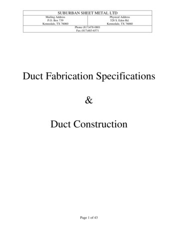
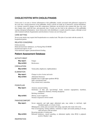
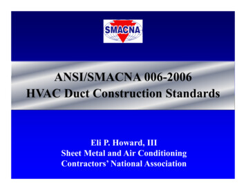
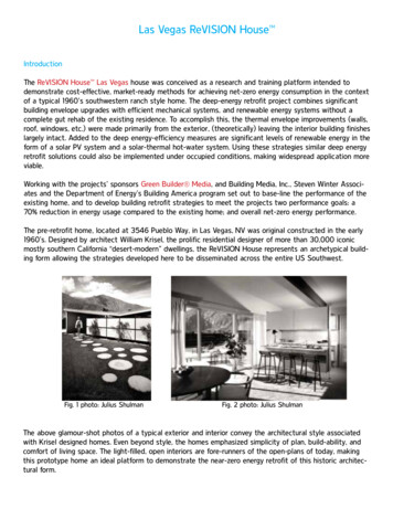
Figure 2 Construction details for an upflow configurationand an upflow configuration with a side return.Figure 3 Construction detail for upflow furnaces with abottom return.sealed and insulated metal, or using faced or coated fibrousglass duct board, will allow a greater opportunity to identifyand correct the air-handling unit issue before other damageoccurs.Application and Construction Detail: Upflow Condition, Side Return. While upflow systems may still experiencewetting due to improper design, they are not as susceptible asthe other two configurations because gravity does not play asignificant role. As shown in Figure 2, in an up-flow configuration, standard uncoated fibrous glass duct board may beused adjacent to the coil.In an upflow configuration with a side return, as detailedin Figure 2, standard uncoated fibrous glass duct board may beused in the return adjacent to the furnace fan.Application and Construction Detail: Upflow Condition, Bottom Return. For upflow furnaces with a bottomreturn, sheet metal should be used in the return ductworkdirectly below the unit, as presented in Figure 3. In addition,the return boot should also be fabricated from sheet metal toprevent any water that may enter the system from collecting inthe boot. From the return boot, standard uncoated fibrous glassduct board may be used for the rest of the return.Application and Construction Detail: HorizontalFlow Condition. In horizontal-flow units, the force of gravityis neutral relative to the airflow, but the force of the airflow isenough to push unwanted condensate into the ductwork. Thiswater may show up as a leak in addition to wetting the duct.There are two options that may be considered, as shownin Figure 4. Metal duct, installed so that it slopes back to thefurnace, may be used for the first four feet of duct adjacent tothe coil. To prevent air infiltration, all seams and connectionsmust be sealed with a UL 181 approved closure system at ductwork joints. In addition, exterior insulation is to be used on the6Figure 4 Construction details for a horizontal supplysystem and a horizontal supply system with ahorizontal return.metal duct to prevent condensation potential. After four feet,the ductwork may be transitioned to standard uncoated fibrousglass duct board.The other option is to use coated or laminated fibrousglass duct board adjacent to the coil for the first four feet.Again, this ductwork should be sloped back toward thefurnace to prevent water from lying in the duct or running outthrough the duct system. All board edges must be sealed witha UL 181 approved closure system prior to fabrication toreduce the surface area of the exposed edge at seams. Standarduncoated fibrous glass duct board may be used after the firstfour feet of coated duct.For a horizontal supply system with a horizontal return,again, standard uncoated fibrous glass duct board may be usedin the return adjacent to the furnace fan, as shown in Figure 4.Application and Construction Detail: DownflowCondition. The worst condition is in a downflow unit, wheregravity carries the condensate in the direction of the airflow.Buildings IX
Any condensate that is carried over from the coil or leaks fromthe drain pan goes directly into the ductwork. For downflowfurnaces, sheet metal should be used directly below the coiland then for four feet in the ductwork adjacent to the coil. Afterfour feet, the ductwork may be transitioned to standarduncoated fibrous glass duct board. This application isdemonstrated in Figure 5.CONCLUSIONThis paper recommends the use of fibrous glass ductboard in many locations. One main advantage of fibrous glassduct systems is that the duct has thermal insulation and doesnot require external insulation. Another advantage is acoustical performance; the material does not transmit vibration andattenuates mid-to-high-frequency equipment and airflownoises effectively. When following the SMACNA’s (1992)recommendations for installation, ducts constructed of fibrousglass duct board will be airtight, durable, resistant to microbialgrowth, and quite effective at attenuation of duct-borne noiseat high frequencies.And a final recommendation—with the increasing availability of the coated and laminated duct boards and the clearlyimproved performance characteristics in cleaning and frictionreduction, the choice should be easy to fabricate all futurefibrous glass duct from the new generation of product.REFERENCESASHRAE. 2001. 2001 ASHRAE Handbook—Fundamentals. Atlanta: American Society of Heating, Refrigerating and Air-Conditioning Engineers, Inc.ICC. 2000. International residential code for one- and twofamily dwellings. Falls Church, Va.: International CodeCouncil.NAIMA. 1996. Fibrous glass HVAC duct systems: Provenperformance. Pub. no. AH100, September. Alexandria,Va.: NAIMA.Buildings IXFigure 5 Construction detail for downflow furnaces.NAIMA. 1997. A guide to insulated air duct systems. Pub.no. AH121, January. Alexandria, Va.: NAIMA.NAIMA. 1998. Cleaning fibrous glass insulated air duct systems recommended practice. Pub. no. AH122, March.Alexandria, Va.: NAIMA.NAIMA. 2002. Fibrous glass duct construction standards,5th ed. Alexandria, Va.: NAIMA.SMACNA. 1992. Fibrous glass duct construction standards,6th ed. Chantilly, Va.: Sheet Metal and Air ConditioningContractors' National Association.Thomann, W.R., and J.J. Tulis. 1996. Fungal contaminationof HVAC surfaces: The role of the dew point in microbial amplification. IAQ 96, Path to Better Building Environments, pp 25-29. Atlanta: American Society ofHeating, Refrigerating and Air-Conditioning Engineers,Inc.7
outlined in NAIMA'S Fibrous Glass Duct Construction Stan-dards, 2nd edition (NAIMA 1997). Fibrous glass ducts are light and can be supported with a typical number of hangers, again following SMACNA or NAIMA standards. Attachment of insulated flex duct to fibrous glass ducts is as simple as spinning in a colla r, sealing the pressure liner, and