Transcription
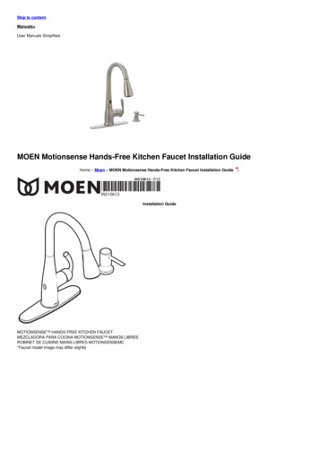
Skip to contentManuals User Manuals Simplified.MOEN Motionsense Hands-Free Kitchen Faucet Installation GuideHome » Moen » MOEN Motionsense Hands-Free Kitchen Faucet Installation GuideInstallation GuideMOTIONSENSE HANDS-FREE KITCHEN FAUCETMEZCLADORA PARA COCINA MOTIONSENSE MANOS LIBRESROBINET DE CUISINE MAINS LIBRES MOTIONSENSEMC*Faucet model image may differ slightly
Not included with all models
* Use only non-rechargeable alkaline batteries.** Optional A/C Adapter with Power Splitter 169031 (sold separately). The outlet for the AC power adapter will require continuous power.Optional Wall Mount Service Kit – 177566 (Sold Separately)Includes: Hose & Hose Bracket, Wall Mounting Bracket & Screws, and Standard Hose Guide NutContents [ hide1 HELPFUL TOOLS2 Parts List3 Recommended configuration4 Optional Control Box on left configuration5 Optional Soap Dispenser on left configuration6 Optional Control Box-wall mounting – Order Kit1775667 Recommended Mounting8 Recommended9 An alternate method to enable Wave Sensor10 Troubleshooting10.1 File Downloads10.2 References10.3 Related ManualsHELPFUL TOOLSFor safety and ease of faucet replacement, Moen recommends the use of these helpful tools.HELPFUL TOOLSFor safety and ease of faucet replacement, Moen recommends the use of these helpful tools.CAUTION — TIPS FOR REMOVAL OF OLD FAUCET :
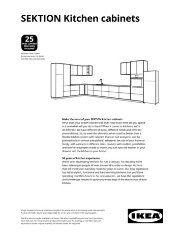
Always turn the water supply OFF before removing the existing faucet or disassembling the valve. Open faucet handles to relieve water pressure and ensure thatcomplete water shut-off has been accomplished.Icon LegendAbove sinkBelow sinkParts ListA. Faucet bodyQ. Hose guide nutB. Spray wandR. Hose weightC. Single hole deck gasketS. Control box & electronic boxD. Pulldown hoseT. Zip tiesE. Data cableU. Hook & loop fastenerF. Hose weight locator markV. Installation toolG. Deck plateW. Mounting screwH. Deck plate gasketX.* Batteries*I. GasketY. Battery holderJ. NutZ.** A/C adapter with Power SplitterK. Soap bottle Not included with all modelsL. Soap pump* Use only non-rechargeable alkaline batteries.M. Base** Sold separatelyN. Support bracketO. Mounting washerP. Mounting nutRecommended configuration
Optional Control Box on left configurationOptional Soap Dispenser on left configuration
Note: minimum 8″ of clearance between faucet and soap dispenser for optimal sensor operationOptional Control Box-wall mounting – Order Kit 177566Recommended Mounting
Before installing the faucet check that the control box will fit under the sink in the areas indicated above. Should you experience any clearance issues trying tomount the control box to the mounting shank, you will need to contact Moen Consumer Support at 1-800-BUY-MOEN or go to www.moen.com to purchase theoptional Wall Mount Service Kit (177566).Optional Wall Mounting Requires Service Kit 177566Available at Moen.com or call 1-800-BUY-MOENFor easier serviceability, mount the control box a minimum 12″ (305mm) above the floor. Select the desired location for the control box (S).Verify supply hoses and data cable, will reach connections on the control box. If using AC power adapter (not provided) ensure that the control box is within 5′(1524mm) from the outlet.Remove the protective label from the sensor on the spout.
Install faucet body (A)–including data cable (E), and single hole deck gasket (C)–in the hole on the sink. Note: Installs with a handle on the right side only.Three Hole Application
For 3 Hole Applications:1.2.3.4.Place deck plate gasket (H) onto deck plate (G).Firmly snap deck plate gasket onto deck plate.Place deck plate on the mounting surface.Install faucet body (A)–including data cable (E)–in the hole on the sink. Note: Installs with a handle on the right side only.Recommended
Option
The recommended mounting procedure is to use a support bracket (N) with a mounting washer (O). It is acceptable to use only a mounting washer (O) on sinksthat will not accommodate the support bracket (N). Important: use care to make sure data cable (E) is not pinched. Tighten the mounting nut by hand.Tighten mounting nut (P) with installation tool (V). Use screwdriver through hole in installation tool (V) to tighten firmly.
Thread hose guide nut (Q) to faucet body (A) mounting shank.Insert the small end of the pulldown hose (D) into the spout and feed through the faucet body (A).
Remove and discard protective cap from spray wand(B) (make sure o-ring and screen are in place). Install spray wand (B) to the upper connection of the pulldown hose (D). Tighten hose nut until flush with spraywand. DO NOT overtighten.1. Remove and discard protective cap from pulldown hose (D).2. Insert pulldown hose (D) into quick connect on the bottom of control box (S). Push in as far as possible until a “click” is heard.3. Tug downward on pulldown hose (D) to test engagement.Insert data cable(E) to the data port on the bottom of the control box (S). Ensure the cable is pushed all the way into the control box.
Attach control box (S) onto hose guide nut (Q) until it snaps into place. This is the recommended orientation for most installations.Control box (S) may also be attached from the left-hand side as shown for optional mounting.
Connect hot and cold hoses to supply valves.Locate hose weight locator mark (F) on pulldown hose (D). Install hose weight (R) just above the start of loop curvature in the hose on the same side of hose aslocator mark (F). Pliers can be used for installation assistance.
Select location for battery holder (Y). Before installation, verify that the battery holder wire will reach the connection on the bottom of the control box (S).Remove cover from battery holder (Y) and install six AA batteries (X) in the same orientation as shown on the cover. Use only non-rechargeable alkaline batteries.Reinstall battery holder cover.Attach battery holder (Y) to the wall with hook & loop fastener (U). First, attach one side of the hook and loop fastener to the wall. Then attach another piece to theback of the battery holder. Option: Attach battery holder to wall with screw (W) provided.
Turn on water supply.Insert battery holder (Y) cable into control box (S) power port. Ensure the cable is pushed all the way into the control box.
Use zip ties (T) if desired to manage faucet hoses, data cable, and battery holder cable. Do not zip tie pulldown hose (D). Check to ensure pulldown hosemovement is not obstructed.
Check to ensure the handle is working properly. Turn on the water with a handle to test that hot and cold water will run. Turn handle off. If water does not flowproperly, see the troubleshooting section on page 18.Check to ensure the wave sensor is working properly. Move hand over wave sensor to test that water will turn on. Move hand over wave sensor again to turn thewater off. If water does not flow properly, see the troubleshooting section on page 18.Disable
To disable Wave Sensor:1. Hold hand over Wave Sensor.2. With the handle in the closed position, rotate the handle from hot to cold three times. The water will stop flowing once the Wave Sensor is disabled.An alternate method to enable Wave SensorAn alternate method to enable Wave Sensor:1. Disconnect Power. Wait 10 seconds.2. Reconnect power.For models with soap dispenser: Insert soap dispenser base (M) through gasket (I) and sinkhole. Note: not included with all models.Tighten nut (J) by hand.Install soap bottle (K) and tighten by hand. Fill the soap bottle with preferred liquid.
Insert soap pump (L) inside the base hole.If low flow, turn off the water at stops before cleaning filters.To remove the in-line filter, push up on the retaining ring and pull down on the supply hose.Hold hose with a wrench at top of the filter connection. Unscrew with a second wrench. Remove filter screen.Rinse debris from the filter screen.Reassemble filter into housing and tighten using two wrenches.Insert hose assembly into the control box. Repeat steps B2-B6 with the second supply hose. Go to step B7.1. Turn on the water at stops.2. Test flow.
1. Unscrew Spray Wand (J) assembly.2. Remove the O-ring and Screen (I).Clean Screen (I) as shown by rinsing it for a few seconds to remove any possible debris. Turn off water before reinstalling Screen and O-ring.1. Re-install the O-ring and Screen (I) into the Spray Wand (J).2. Reattach Spray Wand (J) to Pulldown Hose (L) and tighten.Turn on the faucet to see if the flow has improved. Repeat steps B through D if necessary.Using pliers, make a 1/8 turn. Do not overtighten.TroubleshootingIf the faucet does not appear to be functioning properly, repeat the faucet startup processStartup process definition: Disconnect the battery holder cable (Y) and leave disconnected for 10 seconds. Reinsert battery holder cable (Y) and ensure the cableis pushed all the way into the control box (S) (Refer to step 13).
SymptomProbable Cause(s)1. Data cable is not plugged into control box allthe way.Recommended Action(s)Push data cable firmly into control box (Step 9).2. Power cable is not plugged into control box allthe way.Push power cable firmly into control box (Step 17).3. Batteries not installed properly.Unplug battery holder cable. Install the batteries in proper orientationinto the battery holder (Step 14).4. Batteries are dead in the battery holder.Unplug battery holder cable. Replace batteries with new AA alkalinebatteries (Step 14).5a. If using AC adapter only and electricity is out.Temporarily use the battery holder supplied with the faucet.5b . If using AC adapter with power splitter andelectricity is out.Faucet will function normally until the battery power is depleted.Water does not flow and light is off.6a If using AC adapter only and the wall switch for Turn the wall switch ON to ensure power at outlet. The clear area forpower outlet is OFF.proper startup.Turn the wall switch ON to ensure power at outlet. If the wall switch6b If using AC adapter with power splitter and theremains OFF, the faucet will function normally until battery power iswall switch for power outlet is OFF.depleted.Water does not flow and light is on.1. Water supplies are not turned ON.Turn ON the water supplies (Step 16).1. HOT/COLD/BOTH water supplies are not turnedTurn ON the water supplies (Step 16).ON.Low flow in HOT/COLD/BOTH. OROnly HOT or COLD flow.2. Pinched or kinked hoses.Make sure all hoses are not pinched or kinked.3. Clogged filters.Clean both filters (See pages 16-17).1. Protective label was left on the sensors duringthe faucet startup process.Remove the label from the sensor.2. Sensor is deactivated.Reactivate the sensor (page 14).3. Handle slightly open.Close the handle fully.4. An object is within the range of the sensor.Ensure there are no objects within 8″ of the sensor.Sensor not functioning.1. HOT and COLD hoses are installed in reversed Turn OFF supplies. Connect the HOT supply hose to the HOT stop andorder at wall stops.COLD supply hose to the COLD stop.Handle position for HOT and COLDwater flow is reversed (COLDTurn OFF supplies. Connect the HOT supply hose to the HOT side offorward).2. HOT and COLD hoses are installed in reversedthe control box and COLD supply hose to the COLD side of the controlorder at control box.box (see step A2 for hose removal).Water keeps flowing and does notturn off.Light is blinking1. Battery holder cable unplugged while faucetrunning.Unplug the battery holder cable fully.2. Handle in open position.Close the handle.1. Low battery voltage.Replace batteries with new AA alkaline batteries (Step 14).2. Dead batteries.Replace batteries with new AA alkaline batteries (Step 14).3. Rechargeable batteries being used.Replace with and only use AA alkaline batteries for proper faucetfunctionality (Step 14).
Note:This equipment has been tested and found to comply with the limits for a Class B digital device, pursuant to part 15 of the FCC Rules. These limits are designed toprovide reasonable protection against harmful interference in a residential installation. This equipment generates, uses and can radiate radio frequency energyand, if not installed and used in accordance with the instructions, may cause harmful interference to radio communications. However, there is no guarantee thatinterference will not occur in a particular installation. If this equipment does cause harmful interference to radio or television reception, which can be determinedby turning the equipment off and on, the user is encouraged to try to correct the interferenceby one or more of the following measures:Reorient or relocate the receiving antenna.Increase the separation between the equipment and receiver.Connect the equipment into an outlet on a circuit different from that to which the receiver is connected.Consult the dealer or an experienced radio/TV technician for help.Changes or modifications not expressly approved by Moen Incorporated could void the user’s authority to operate the equipment.Moen Limited Lifetime WarrantyMotionSense System Limited Warranty1. Identity and Types of Warranty Holdersi. “Original Consumer Purchaser” means the owner-of-record of a single-family residential owner-occupied dwelling in which the Product is initially installed(or, if installed by a builder/contractor/owner, the owner-of-record to whom the builder/ contractor/owner first transfers the single-family dwelling), but only solong as such Purchaser owns the single-family dwelling where the Product was installed, and subject to the additional restrictions stated below.ii. All others who do not fit within the definition of “Original Consumer Purchaser,” but who have purchased the Product, are considered an “OriginalCommercial Purchaser,” but only so long as such Purchaser owns the premises where the Product was installed, and subject to the additional restrictionsstated below.What is Covered by This Limited Warranty and the Applicable Warranty PeriodsMoen “(Seller”) warrants that the MotionSense System (“the Product”) will be free from defects in materials and manufacturing workmanship. Moen warrantsthat the faucet will be leak-free and drip-free under normal use, and that the Product’s control box (which houses the hydraulic system) and finish will be free fromdefects in material and manufacturing workmanship for (1) the lifetime of the Original Consumer Purchaser; or (2) five years from the date of purchase for theOriginal Commercial Purchaser (but only so long as the Original Consumer/Commercial Purchaser continues to own the dwelling or premises). The warranty onall other components of the Product, including but not limited to the electronics box, spout, and lenses, runs for: (1) five years from the date of purchase for anOriginal Consumer Purchaser; or (2) one year from date of purchase for an Original Commercial Purchaser (but only so long as the OriginalConsumer/Commercial Purchaser continues to own the dwelling or premises). This Limited Warranty may not be transferred to subsequent owners of the dwellingor premises, or to any other person.What This Limited Warranty Does Not CoverThis Limited Warranty covers only those workmanship and material non-conformities specified above and does cover non-conformities or damages arising fromany other cause, including without limitation, defects or damage due to the use of other than genuine Moen parts, due to installation error, product abuse, orproduct misuse or due to the use of cleaners containing abrasives, alcohol or other organic solvents.Buyer’s Sole And Exclusive Remedy Under This Limited WarrantyIn the event of a non-conformity in workmanship or materials in one or more components of the Product, Seller’s sole obligation is, at its sole option, to repair orreplace any non-conforming component, or refund the Product’s purchase price. This is the warranty holder’s sole and exclusive remedy for the Product under thisLimited Warranty. By way of example but not limitation, the following costs and expenses are not covered by this Limited Warranty: (i) labor costs for the removal,reinstallation, or refinishing of the Product, or non conforming part thereof (or of building materials which must be removed, reinstalled or refinished in order torepair or replace the non-conforming Product); (ii) shipping and freight expenses required to return Product to Seller. Repaired or replaced components areindividually warranted only under the same terms and for the remaining balance of the Limited Warranty period applicable to that component(s) which is/arerepaired or replaced.DISCLAIMER OF WARRANTIESTHE FOREGOING LIMITED WARRANTY IS IN LIEU OF AND EXCLUDES ALL OTHER WARRANTIES NOT EXPRESSLY SET FORTH HEREIN, WHETHEREXPRESS OR IMPLIED, BY OPERATION OF LAW OR OTHERWISE, INCLUDING BUT NOT LIMITED TO ANY IMPLIED WARRANTIES OFMERCHANTABILITY OR FITNESS FOR A PARTICULAR PURPOSE. TO THE EXTENT THAT ANY IMPLIED WARRANTIES MAY NONETHELESS EXIST BYOPERATION OF LAW, ANY SUCH WARRANTIES ARE LIMITED TO THE DURATION PROVIDED BY THAT LAW. SOME STATES/ PROVINCES DO NOTALLOW LIMITATIONS ON HOW LONG AN IMPLIED WARRANTY LASTS, SO THE ABOVE LIMITATIONS MAY NOT APPLY TO YOU.LIMITATION OF LIABILITYSELLER’S SOLE LIABILITY UNDER THIS LIMITED WARRANTY SHALL BE REPLACEMENT OR REPAIR, OR REFUND OF THE PURCHASE PRICE ASSET FORTH ABOVE. IN NO EVENT, WILL THE SELLER BE LIABLE FOR INCIDENTAL, CONSEQUENTIAL, INDIRECT, SPECIAL, OR PUNITIVEDAMAGES INCLUDING, BUT NOT LIMITED TO, LABOR, REMOVAL, REINSTALLATION, REFINISHING, LOSS OF USE OF THE PRODUCT, LOSS OFPROFITS, LOSS OF REVENUE, LOST GOODWILL, CLAIMS OF EMOTIONAL DISTRESS, OR CLAIMS OF WARRANTY HOLDERS’ CUSTOMERS,WHETHER BASED ON CONTRACT, WARRANTY, TORT (INCLUDING, BUT NOT LIMITED TO, STRICT LIABILITY OR NEGLIGENCE) OR OTHERWISE,EVEN IF ADVISED OF THE POSSIBILITY OF SUCH DAMAGES? SOME STATES DO NOT ALLOW THE EXCLUSION OR LIMITATION OF INCIDENTAL ORCONSEQUENTIAL DAMAGES, SO THE ABOVE LIMITATION OR EXCLUSION MAY NOT APPLY TO YOU. THIS LIMITED WARRANTY GIVES YOUSPECIFIC LEGAL RIGHTS AND YOU MAY ALSO HAVE OTHER RIGHTS WHICH VARY FROM STATE TO STATE, AND PROVINCE TO PROVINCE. EVENIF THIS LIMITED WARRANTY IS DEEMED TO HAVE FAILED OF ITS ESSENTIAL PURPOSE, IN NO EVENT WILL THE SELLER’S ENTIRE LIABILITYEXCEED THE PURCHASE PRICE OF THE PRODUCT WARRANTED HEREUNDER, OR THE NON-CONFORMING PORTION THEREOF, WHICHEVER ISTHE LESSER AMOUNT.Warranty ClaimsTo initiate a claim, call Moen at 800-289-6636 (800-465-6130 in Canada; 01-800-718-4345 in Mexico), or write Moen at the address on the reverse side.Proof of purchase is required.Buy it looks. Buy it for life. Moen Incorporated25300 Al Moen DriveNorth Olmsted, Ohio 44070-8022U.S.A.
Moen de Mexico, S.A. de C.V.Carretera Saltillo-Monterrey KM 14.7Ramos Arizpe, CoahuilaMexico 25900Moen Inc.2816 Bristol CircleOakville, Ontario L6H 5S7CanadaINS10613 – 7/17 2017 Moen IncorporatedFile DownloadsInstallation GuideDownload [optimized]Motionsense Hands-Free Kitchen Faucet DownloadReferencesMoen Bathroom & Kitchen Faucets, Shower Heads, Accessories & More Cart Moen Search close Search Menu Arrow - Dark Arrow - DarkArrow - Dark Arrow - Dark Arrow - Dark Arrow - Dark Arrow - Dark Arrow - Dark Arrow - Dark Small Arrow Arrow - Dark Small ArrowMOTIONSENSE TrademarkRelated Manuals1.2.3.4.5.6.Kraus Bolden Single Handle Pull Down Kitchen Faucet Instruction Manual Bolden TM Single Handle Pull Down Kitchen Faucet KPF-1610 INSTALLATION.anko Bluetooth Hands Free Kit User Manual anko Bluetooth Hands Free Kit User Manual Notice Please.Himbox Bluetooth HB01 Hands-Free Car Kit User Manual [Himbox-HB01] Bluetooth Hands-Free Car Kit User Manual This Himbox Bluetooth.Av:link BTR1 Bluetooth Audio & Hands-free Receiver User Manual Bluetooth Audio & Hands-free Receiver Transform any audio device with.abode Kitchen Tap Althia Monobloc Installation Guide Althia Monobloc 5-year warranty Terms and Conditions In the unlikely.RUVATI Granite Composite Kitchen Sinks Installation Guide RUVATI Granite Composite Kitchen Sinks ATTENTION INSTALLER Read these instructions.
Always turn the water supply OFF before removing the existing faucet or disassembling the valve. Open faucet handles to relieve water pressure and ensure that complete water shut-off has been accomplished. Icon Legend Above sink Below sink Parts List A. Faucet body Q. Hose guide nut B. Spray wand R. Hose weight