Transcription
Cisco Unified ICMACD Supplement forVRU Peripheral GatewayFebruary 2010Corporate HeadquartersCisco Systems, Inc.170 West Tasman DriveSan Jose, CA 95134-1706USAhttp://www.cisco.comTel: 408 526-4000800 553-NETS (64387)Fax: 408 526-4100
THE SPECIFICATIONS AND INFORMATION REGARDING THE PRODUCTS IN THIS MANUAL ARE SUBJECT TO CHANGE WITHOUTNOTICE. ALL STATEMENTS, INFORMATION, AND RECOMMENDATIONS IN THIS MANUAL ARE BELIEVED TO BE ACCURATE BUT AREPRESENTED WITHOUT WARRANTY OF ANY KIND, EXPRESS OR IMPLIED. USERS MUST TAKE FULL RESPONSIBILITY FOR THEIRAPPLICATION OF ANY PRODUCTS.THE SOFTWARE LICENSE AND LIMITED WARRANTY FOR THE ACCOMPANYING PRODUCT ARE SET FORTH IN THE INFORMATIONPACKET THAT SHIPPED WITH THE PRODUCT AND ARE INCORPORATED HEREIN BY THIS REFERENCE. IF YOU ARE UNABLE TOLOCATE THE SOFTWARE LICENSE OR LIMITED WARRANTY, CONTACT YOUR CISCO REPRESENTATIVE FOR A COPY.The Cisco implementation of TCP header compression is an adaptation of a program developed by the University of California, Berkeley (UCB)as part of UCBs public domain version of the UNIX operating system. All rights reserved. Copyright 1981, Regents of the University ofCalifornia.NOTWITHSTANDING ANY OTHER WARRANTY HEREIN, ALL DOCUMENT FILES AND SOFTWARE OF THESE SUPPLIERS AREPROVIDED "AS IS" WITH ALL FAULTS. CISCO AND THE ABOVE-NAMED SUPPLIERS DISCLAIM ALL WARRANTIES, EXPRESSED ORIMPLIED, INCLUDING, WITHOUT LIMITATION, THOSE OF MERCHANTABILITY, FITNESS FOR A PARTICULAR PURPOSE ANDNONINFRINGEMENT OR ARISING FROM A COURSE OF DEALING, USAGE, OR TRADE PRACTICE.IN NO EVENT SHALL CISCO OR ITS SUPPLIERS BE LIABLE FOR ANY INDIRECT, SPECIAL, CONSEQUENTIAL, OR INCIDENTALDAMAGES, INCLUDING, WITHOUT LIMITATION, LOST PROFITS OR LOSS OR DAMAGE TO DATA ARISING OUT OF THE USE ORINABILITY TO USE THIS MANUAL, EVEN IF CISCO OR ITS SUPPLIERS HAVE BEEN ADVISED OF THE POSSIBILITY OF SUCHDAMAGES.CCDE, CCENT, CCSI, Cisco Eos, Cisco HealthPresence, Cisco IronPort, the Cisco logo, Cisco Nurse Connect, Cisco Pulse, Cisco SensorBase,Cisco StackPower, Cisco StadiumVision, Cisco TelePresence, Cisco Unified Computing System, Cisco WebEx, DCE, Flip Channels, Flip forGood, Flip Mino, Flipshare (Design), Flip Ultra, Flip Video, Flip Video (Design), Instant Broadband, and Welcome to the Human Network aretrademarks; Changing the Way We Work, Live, Play, and Learn, Cisco Capital, Cisco Capital (Design), Cisco:Financed (Stylized), Cisco Store,Flip Gift Card, and One Million Acts of Green are service marks; and Access Registrar, Aironet, AllTouch, AsyncOS, Bringing the Meeting ToYou, Catalyst, CCDA, CCDP, CCIE, CCIP, CCNA, CCNP, CCSP, CCVP, Cisco, the Cisco Certified Internetwork Expert logo, Cisco IOS,Cisco Lumin, Cisco Nexus, Cisco Press, Cisco Systems, Cisco Systems Capital, the Cisco Systems logo, Cisco Unity, Collaboration WithoutLimitation, Continuum, EtherFast, EtherSwitch, Event Center, Explorer, Follow Me Browsing, GainMaker, iLYNX, IOS, iPhone, IronPort, theIronPort logo, Laser Link, LightStream, Linksys, MeetingPlace, MeetingPlace Chime Sound, MGX, Networkers, Networking Academy, PCNow,PIX, PowerKEY, PowerPanels, PowerTV, PowerTV (Design), PowerVu, Prisma, ProConnect, ROSA, SenderBase, SMARTnet, Spectrum Expert,StackWise, WebEx, and the WebEx logo are registered trademarks of Cisco Systems, Inc. and/or its affiliates in the United States and certainother countries.All other trademarks mentioned in this document or website are the property of their respective owners. The use of the word partner does notimply a partnership relationship between Cisco and any other company. (0910R)Any Internet Protocol (IP) addresses used in this document are not intended to be actual addresses. Any examples, command display output,and figures included in the document are shown for illustrative purposes only. Any use of actual IP addresses in illustrative content isunintentional and coincidental.Cisco Unified ICM ACD Supplement for VRU Peripheral GatewayCopyright 2010 Cisco Systems, Inc.All rights reserved.
ContentsPreface. vi1. Overview . 91.1. ICM/VRU Configuration . 101.2. VRU Interface Requirements . 101.3. Hardware and Software Requirements . 101.4. Supported Unified ICM Features . 111.5. Unsupported Unified ICM Features . 112. VRU Service Control Interface . 133. VRU Time Synchronization Interface. 154. Older VRU Interface Features . 174.1. Event Data Feed . 184.2. Call Routing Interface . 184.3. Mixing SCI and EDF . 185. VRU PG Installation Options . 195.1. Installation Options . 205.2. MIS Enabled checkbox. 205.3. VRU Reporting controls . 205.3.1. Event Feed choice . 215.3.2. Service Control choice . 216. Unified ICM Configuration . 236.1. Peripheral . 24
iv6.2. Peripheral Targets . 246.2.1. Event Feed VRUs . 246.2.2. Call Routing VRUs . 256.3. Trunk Groups . 256.4. Trunks . 256.5. Services . 256.6. Translation Routes . 256.7. Routes. 256.8. Routing Client . 256.9. Labels . 266.10. Network Trunk Groups. 266.11. Service Arrays . 276.12. Maintaining Your Configuration . 277. VRU Programming Considerations . 297.1. VRU Script Timeout . 307.2. Translation Routing . 307.2.1. SCI 307.2.2. CRI with EDF . 307.2.3. CRI without EDF . 31Index . Index-1iv
vFiguresFigure 1: Configuration. 10Figure 2: Installation Options . 20Figure 3: Network Trunk Groups . 26vv
viPrefacePrefacePurposeThis document provides configuration information specific to the VRUPeripheral Gateway (PG). The VRU PG implements the UnifiedICM/VRU Interface Protocol (here after called VRU Interface). The VRUPG allows Cisco Systems, end users, VRU vendors, and other parties tointegrate various telephony devices (here after called VRU) into UnifiedICM. It is not within the scope of this document to address the specifics ofany particular VRU that was integrated. This document providesinformation that may be generally applied to any VRU connected toUnified ICM through the VRU PG.AudienceThis document is intended for system managers. The reader shouldunderstand Unified ICM functions as described in the Installation andSetup Guide for Cisco Unified ICM/Contact Center Enterprise & Hosted,Configuration Guide for Cisco Unified ICM/Contact Center Enterprise &Hosted, and Scripting and Media Routing Guide for Cisco UnifiedICM/Contact Center Enterprise & Hosted. The reader is also assumed tohave specific knowledge of the VRU Interface, as well as specificknowledge about one or more VRU Interface implementations.OrganizationChapter 1, “Overview”Provides an overview of the VRU interface, software and hardwarerequirements.Chapter 2, “VRU Service Control Interface”Describes the Service Control Interface that is used to control a VRU.Chapter 3, “Time Synchronization Interface”Describes how the VRU can use the TSI to synchronize its internalclock with the VRU PG.Chapter 4, “Old Interfaces of VRU”Describes some of the older interfaces of the VRU.Chapter 5, “VRU PG Installation Options”Describes the installation options of the VRU PG.Chapter 6, “Unified ICM VRU Configuration”Describes the configuration details of the Unified ICM and the VRUPG.vi
viiPrefaceChapter 7, “VRU Programming Considerations”Describes the programming considerations for the VRU PG.Typographic ConventionsThis manual uses the following conventions: Boldface type is used for emphasis; for example:Real-time information is not stored in the central database. Italic type indicates one of the following: A newly introduced term; for example:A skill group is a collection of agents who share similar skills. A generic syntax item that you must replace with a specific value;for example:IF (condition, true-value, false-value) A title of a publication; for example:For more information see the Installation and Setup Guide forCisco Unified ICM/Contact Center Enterprise & Hosted. Sans serif type with small caps is used to represent keys on yourkeyboard; for example:Press the Shift key to select a range of items. An arrow ( ) indicates an item from a pull-down menu. For example,the Save command from the File menu is referenced as File Save.Other PublicationsFor more information on Unified ICM, see the following documents: Administration Guide for Cisco Unified ICM/Contact CenterEnterprise & Hosted Installation and Setup Guide for Cisco Unified ICM/Contact CenterEnterprise & Hosted Configuration Guide for Cisco Unified ICM/Contact CenterEnterprise & Hosted Scripting and Media Routing Guide for Cisco Unified ICM/ContactCenter Enterprise & HostedFor information on Cisco Network Applications Manager (NAM), see thefollowing documents: Product Description Guide for Cisco Unified ICM Hosted Setup and Configuration Guide for Cisco Unified ICM Hosted Edition Multiple-NAM Setup and Configuration Guide for Cisco Unified ICMHostedviivii
viiiPrefaceObtaining Documentation, Obtaining Support, and SecurityGuidelinesFor information on obtaining documentation, obtaining support, securityguidelines, and also recommended aliases and general Cisco documents,see the monthly What's New in Cisco Product Documentation, which alsolists all new and revised Cisco technical documentation, w/whatsnew.htmlDocumentation FeedbackYou can provide comments about this document by sending email to thefollowing address: ccbu docfeedback@cisco.comWe appreciate your comments.viii
91. OverviewThe VRU PG connects to each VRU via a TCP/IP connection. The VRUPG can run in simplex or duplex configurations.In a duplex configuration, only the active side of the PG connects to theVRU. If the active side of a duplexed PG fails, the inactive side isactivated, and a new connection to the VRU opens.
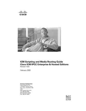
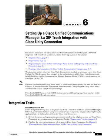
10Overview1.1. ICM/VRU ConfigurationThe typical configuration consists of a VRU system and a PG (or two PG’sif duplexed) on an Ethernet hub. Each VRU PG is capable of connecting32 VRUs simultaneously.10 Base-TEthernet HubPG AVRUPG BFig u re 1: Co nfig u ra tio nNote: Bandwidth to the Central Controller is sufficient to support the number ofVRUs connected. Contact your Cisco representative for a networkanalysis.1.2. VRU Interface RequirementsThe VRU PG requires a TCP/IP connection to the VRU. The VRU mustprovide an IP address and a TCP port number for the PG to connect to.The VRU must implement the required interface defined in the documentCisco Unified ICM/VRU Interface Specification.1.3. Hardware and Software RequirementsThe VRU PG requires a 10-Megabit Ethernet or equivalent physicalconnection to the VRU. The VRU PG can communicate remotely withVRUs via a TCP/IP network. However, you must ensure that the networklink between the PG and VRU system has the bandwidth to support thecall load for VRU.10
Unsupported Unified11 ICM Features1.4. Supported Unified ICM FeaturesThe VRU PG supports the following Unified ICM features: Pre-RoutingPost-RoutingTranslation RoutingPeripheral, Trunk Group and Service real time reportingDuplexed PG implementation1.5. Unsupported Unified ICM FeaturesThe VRU PG does not support features pertaining to Agents or CallQueuing. An SCI VRU allows the CallRouter to implement call queueswithout implementing the queues.1111
1212Overview
132. VRU Service ControlInterfaceA CallRouter uses the Service Control Interface (SCI) to control a VRU.The CallRouter can have the VRU play announcements and prompts,gather data from the caller, and route calls to destinations. This interface isrequired for in-network VRUs and for global call queues implemented inthe CallRouter.Because SCI allows the CallRouter to control the VRU, the CallRouterneeds to know the capabilities and configuration of the VRU. This isencoded in a number called the VRU Type configured in the Routersettings. See the "Network VRUs" chapter of the Scripting and MediaRouting Guide for Cisco Unified ICM/Contact Center Enterprise &Hosted for details on choosing and configuring the VRU Type for differentapplications.
1414VRU Service Control Interface
153. VRU Time SynchronizationInterfaceThe VRU can use the Time Synchonization Interface (TSI) to synchronizeits internal clock with VRU PG clock, which is synchronized to theUnified ICM clock. As certain messages arrive from the VRU, the VRUPG compares VRU time stamp with Unified ICM time. Significantdifferences are periodically reported to the VRU via the TSI.The messages that contain the current VRU time:SCI:INIT SERVICE CONTROL VRU, VRU STATUSEDF:INIT DATA END EVENT, VRU STATUS EVENTWarning: The Time Synchronization Interface should not be used on anyVRU which is connected to a PG and is being used as Unified ICM TimeSource (Router registry key "Router \ CurrentVersion \ Configuration \Time \ Source"). This can cause a time feedback loop that can result insystem time to fluctuate.
1616VRU Time Synchronization Interface
174. Older VRU InterfaceFeaturesThe Service Control Interface feature replaces several earlier interfacefeatures that are still supported for backward compatibility with thefollowing older VRUs: Event Data Feed (EDF)Call Routing Interface (CRI)
18Older VRU Interface Features4.1. Event Data FeedThe VRU uses EDF feature to provide real-time events to Unified ICM.Unified ICM will accumulate call time statistics and write TerminationCall Detail records for each call.4.2. Call Routing InterfaceThe VRU uses CRI feature to send route requests to the CallRouter. Eachroute request triggers a routing script, which returns a route response.Typically, the route response is to direct the call to a new destination.However, the script triggered by the route request can perform anydecision-making or data-gathering task (such as a database lookup) andreturn the result in a route response. You can use this as a standaloneinterface. However, this is generally used in conjunction with the EDF .4.3. Mixing SCI and EDFA VRU can support both SCI and EDF. This capability is provided as amigration path from legacy EDF applications to SCI. The VRU can deliversome calls under EDF (send a "delivered" event) and the others under SCI(send a "New Call" or "Request Instruction" message). If the VRU is notable to determine which mode to use based on data available when the callis delivered, it must start the call under EDF (send a "delivered" event) andlater use SCI "New Dialogue" message to convert EDF call to an SCIdialogue.18
195. VRU PG Installation OptionsThis chapter describes the options available during the installation of aVRU PG.
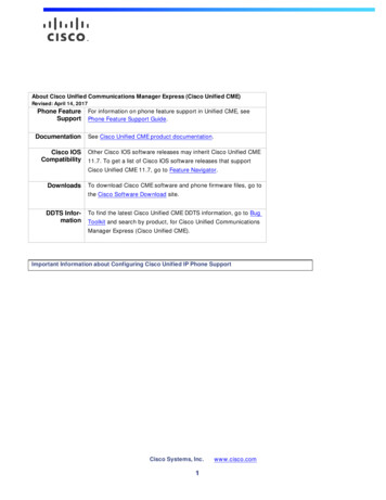
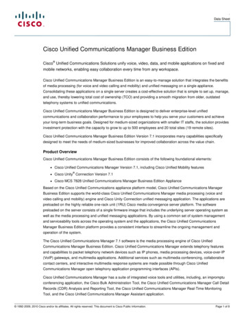
20VRU PG Installation Options5.1. Installation OptionsFollowing are the installation options available in the VRU PG:Fig u re 2: In s tallatio n Op tio n s5.2. MIS Enabled checkboxMIS is used to transfer the call variables between an ACD and associatedEDF/CRI VRU. Check the box to use MIS.5.3. VRU Reporting controlsSelect one of the two options: Event FeedService ControlNote: The names of these two options do not directly correspondence to theVRU Interface features of similar name. The features that the VRU cansupport are restricted by the choice. But within those restrictions, thecombination of features that the VRU chooses to support are left to theVRU and are received from the VRU when the VRU PG connects to it.20
VRU Reportingcontrols21215.3.1. Event Feed choiceIf this option is selected, VRU PG will not generate real-time trunk, updateservice data and write Ternimation Call Detail records for every SCIdialogue. VRU PG still generates real-time peripheral data update. If theService Control Interface is used as a standalone, VRU peripheral data isinitialized based on the Init Service Ctrl VRU message during the SCIinitialization. If Service Control Interface is used along with EDFinterface, VRU peripheral data is initialized by messages in EDF interface.5.3.2. Service Control choiceSelecting this option allows the VRU PG to generate real-time peripheral,trunk and service data update, and write one or more Termination CallDetail records for each SCI dialogue. For Service Control Interface, VRUperipheral data is always initialized based on Init Service Ctrl VRUmessage during the SCI initialization, even if Service Control Interface isused alone, or combined with other interface.Selecting this option also enables the Queue Reporting checkbox.Queue Reporting checkboxIf this box is unchecked, the only events generated for SCI dialogues areDelivered and Cleared, and the only call statistic calculated is total calltime.If this box is checked, the PG will generate Queue events. Calculated callstatistics will include queue times and abandons in-queue time, and totalcall time.21
2222VRU PG Installation Options
236. Unified ICM ConfigurationIn Unified ICM terms, the VRU itself corresponds to a peripheral. UnifiedICM treats all contact center devices (e.g., ACDs, PBXs, IVR systems) asperipherals.To properly configure and maintain Unified ICM database, you need tounderstand the relationship between the objects configured in the VRU,and the Unified ICM database, relationship of the field in the VRUmessage, and the attribute of objects in Unified ICM database.Some mappings are described in this chapter. For example, a Unified ICMTrunk Group Peripheral Number corresponds to the Trunk Group ID valuein the VRU messages.Note: Different VRU vendors may use different object names; refer tothe document from the VRU vendor for detailed object mapping. Thischapter also provides information specific to configuring a VRU PG usingthe Configuration Manager's PG Explorer tool.
24Unified ICM Configuration6.1. PeripheralThe Unified ICM Peripheral corresponds to the VRU. The followingvalues can be used in any combination in the Peripheral ConfigurationParameter for the Peripherals configured with the VRU PG: "/BTTELSIS": Send a single-byte pad message, after any messagewith odd length is sent to the VRU, and read a single-byte message,after any message with odd length is received from the VRU. Thedefault action is to block or read pad messages. "/ZEROTRUNKS": Tell the Unified ICM to set the available trunkcount to zero if the VRU PG goes out of service. "/FILTERVARS": Send only the call variables changed by UnifiedICM to the VRU, since the last time the call variables were sent to orreceived from the VRU. The default action is to send all non-null callvariables to the VRU. "/ASSUME ANSWERED": Count calls as successfully connectedas soon as the Connect message is sent to the VRU. This will preventcalls from being counted as abandoned when a VRU fails to send anEvent Report / Answered message in response to a Connect message. "/TYPE 3 TALK TIME ": This value is used to support customerswho might be relying on the old behavior that when Service ControlQueue Reporting is enabled, VRUPIM treat the call arrived at Type3or Type 7 VRU for self-service as in Talking state and the TalkTime inTCD is the time the call spent at VRU. The new behavior is to treatcalls arriving at Type 3 and Type 7 VRUs the same as Type 2 andType 8 VRUs and the TalkTime in TCD is not incremented for selfservice call at VRU when Service Control Queue Reporting is enabled.6.2. Peripheral TargetsA Peripheral Target is a network target identified by a Trunk Group andDNIS that terminates on the VRU. For EDF, a Peripheral Target must beconfigured for all DNIS and Trunk Group(s) through which an incomingcall arrives. Peripheral Targets used for Translation Routes can be mosteasily built with the Translation Route Wizard.6.2.1. Event Feed VRUsAll Trunk Group/DNIS combinations that are in any way connected withthe handling of any incoming VRU call should be configured in theUnified ICM as a Peripheral Target to ensure complete call monitoring.Those calls that do not map to a valid Peripheral Target are associated withthe Service defined in the Delivered or Originated call event. If neithermapping fits, the call is associated with the Peripheral’s Default Route asdefined in the Peripheral Configuration Table. If a Default Route is notdefined, the PG will log an event.24
25 Routing ClientThe OPC Registry variable “MapPeripheralTargetsWithoutTrunkGroup”must be set to the default value of zero for Event Data Feed VRUs.6.2.2. Call Routing VRUsConfiguration of all Trunk Group/DNIS combinations as PeripheralTargets is not essential. However, Peripheral Targets necessary for PostRouting / Translation Routing must still be configured.The OPC Registry variable “MapPeripheralTargetsWithoutTrunkGroup”must be changed to 1 for Call Routing-only VRUs.6.3. Trunk GroupsThe Trunk Group Peripheral Number corresponds to the Trunk Group IDvalue in VRU messages. No special configuration information is requiredfor Trunk Groups for the VRU PG. The trunk count is obtaineddynamically from the VRU and should not be configured. The VRU PGdoes not use the Trunk Group Extension.6.4. TrunksIncoming calls are identified according to the individual trunk or port thatthe call occupies. However, there is no need to configure individual trunksin Unified ICM; the identification of trunks is handled automatically bythe VRU and the VRU PG.6.5. ServicesThe Service Peripheral Number corresponds to the Service ID value inVRU messages.6.6. Translation RoutesNo special configuration considerations apply.6.7. RoutesA Route is one or more Peripheral Targets. A Peripheral Target is anetwork target identified by a Trunk Group and DNIS that terminates onthe VRU. A Peripheral Target is equivalent to the combination of DNISand the Trunk Group(s) through which the incoming calls arrive.6.8. Routing ClientThe VRU PG supports post routing and can therefore be considered aRouting Client. To configure a Routing Client for the VRU, select theVRU Peripheral's "Routing Client" Tab in PG Explorer and set the ClientType to "VRU" through Configuration Manager.2525
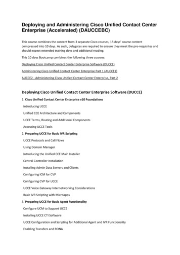
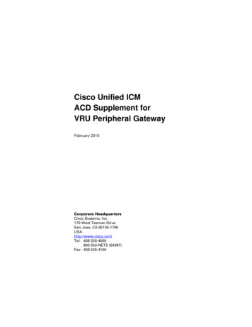
26Unified ICM Configuration6.9. LabelsThe format of label strings sent to the VRU in a Route Select, Connect,Temporary Connect, or Connect-to-Resource message is not dictated bythe Unified ICM. The VRU is responsible for interpreting the label andacting upon it; this interpretation may vary from one VRU implementationto another.For labels of type BUSY, RING, and DEFAULT the label type configuredin the Unified ICM is passed to the VRU in Route Select and Connectmessages. Other label types are marked as type NORMAL. The VRU mayuse the label type (where available), in addition to the label itself, todetermine how to process the response.6.10. Network Trunk GroupsUnified ICM supports a configuration in which several VRUs share asingle Network Trunk Group. In this configuration, the physical VRUscombine to give the appearance of a single “virtual” VRU with increasedcapacity. Since the network can deliver a call on any trunk in the NetworkTrunk Group, the call may arrive on any of the VRUs sharing the NetworkTrunk Group. For this reason, all the VRUs sharing the Network TrunkGroup should perform identical call processing.VRU 1Trunk GroupVRU 1VRU 2Trunk GroupNetwork Trunk GroupNetworkVRU 2VRU 3Trunk GroupVRU 3"Virtual" VRUFig u re 3: Network Tru nk Gro u p sConfigure one Network Trunk Group for the “virtual” VRU. Then, foreach physical VRU, configure the Trunk Group(s) on that peripheral. Setthe Network Trunk Group for each peripheral Trunk Group to be theNetwork Trunk Group for the “virtual” VRU.Note that all Peripheral Targets associated with any of the VRUs aredefined in terms of the Network Trunk Group. It is therefore not possible26
Maintaining Your27 Configuration27to route calls to an individual VRU in this configuration. Calls may berouted to the “virtual” VRU; you cannot predict which physical VRU willactually receive the call. Monitoring of call activity on either the “virtual”VRU or any of the physical VRUs can be done by examining the data forthe Network Trunk Group or the peripheral Trunk Group, respectively.All physical VRUs that comprise a “virtual” VRU must be connected tothe same VRU PG.6.11. Service ArraysA Service Array is similar to a Network Trunk Group but aggregatesServices instead of Trunk Groups.In a “virtual” VRU, each physical VRU must be configured andprogrammed to perform the same call processing. This implies that eachphysical VRU must have the same Service(s) configured. However,because of the shared Network Trunk Group, the Unified ICM cannottarget a call for a Service on a specific VRU within a “virtual” VRU.Instead, a Service Array is used for this purpose. A Service Array defines a“virtual” Service on a “virtual” VRU, and may be used as a Skill Target ina Unified ICM routing script.To configure a Service Array:1. Configure a Service for every physical VRU in the “virtual” VRU.2. Create a Service Array.3. Add the Services configured for the physical VRUs as members of theService Array.Note: It is required to have one Service from each VRU in the“virtual” VRU that is a member of the Service Array.For example, suppose the 3 VRUs in the diagram above can service“Sales” callers and “TechSupport” callers. Six services would beconfigured; for example: VRU 1.Sales, VRU 2.Sales, VRU 3.Sales,VRU 1.TechSupport, VRU 2.TechSupport, and VRU 3.TechSupport.Then, two Service Arrays would be configured; for example: VRUSalesand VRUTechSupport. VRUSales would include VRU 1.Sales,VRU 2.Sales, and VRU 3.Sales as members. VRUTechSupport wouldinclude VRU 1.TechSupport, VRU 2.TechSupport, andVRU 3.TechSupport as members.6.12. Maintaining Your ConfigurationIt is preferred that changes made to your configuration be accomplishedfirst on the VRU, then on the Unified ICM Configuration. This will ensurethat the PG sees the configuration updates on the VRU systems.27
2828Unified ICM Configuration
297. VRU ProgrammingConsiderationsThis chapter describes the programming considerations for the VRUenvironment.
30VRU Programming Considerations7.1. VRU Script TimeoutWhen the CallRouter encounters a Run VRU Script node in a routingscript, it sends a Run VRU Script request to a Service Control VRU andstarts a timer. If the Script Result response does not arrive from the VRUbefore the timer expires, the CallRouter will take the failure path from theRun VRU Script node and continue processing. The VRU PG and theVRU are not notified of the timeout.The default timeout value is 3 minutes but the value can be configured foreach Network VRU Script. The timeout value should be set higher than thelongest that the VRU script is expected to execute.7.2. Translation RoutingWhen a VRU is the target of a translation route, the call arrives at the VRUwith a DNIS reserved for translation routing. This DNIS must be presentedto Unified ICM so that the arriving call can be associated with the existingcall context information. How the DNIS is presented to the Unified ICMdepends on the interface feature being used.7.2.1. SCIWhen a translation-routed call arrives at the VRU, the VRU mustrecognize the call as being a translation route connection and send aRequest Instruction message to the VRU PG. The
Cisco Unified ICM ACD Supplement for VRU Peripheral Gateway February 2010 Corporate Headquarters Cisco Systems, Inc. 170 West Tasman Drive San Jose, CA 95134-1706 . CCDE, CCENT, CCSI, Cisco Eos, Cisco HealthPresence, Cisco IronPort, the Cisco logo, Cisco Nurse Connect, Cisco Pulse, Cisco SensorBase, .