Transcription
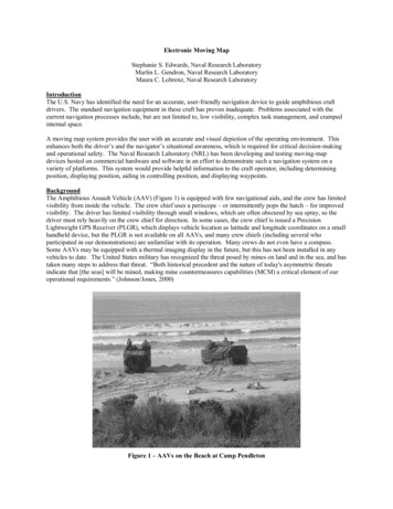
Electronic Moving MapStephanie S. Edwards, Naval Research LaboratoryMarlin L. Gendron, Naval Research LaboratoryMaura C. Lohrenz, Naval Research LaboratoryIntroductionThe U.S. Navy has identified the need for an accurate, user-friendly navigation device to guide amphibious craftdrivers. The standard navigation equipment in these craft has proven inadequate. Problems associated with thecurrent navigation processes include, but are not limited to, low visibility, complex task management, and crampedinternal space.A moving map system provides the user with an accurate and visual depiction of the operating environment. Thisenhances both the driver’s and the navigator’s situational awareness, which is required for critical decision-makingand operational safety. The Naval Research Laboratory (NRL) has been developing and testing moving-mapdevices hosted on commercial hardware and software in an effort to demonstrate such a navigation system on avariety of platforms. This system would provide helpful information to the craft operator, including determiningposition, displaying position, aiding in controlling position, and displaying waypoints.BackgroundThe Amphibious Assault Vehicle (AAV) (Figure 1) is equipped with few navigational aids, and the crew has limitedvisibility from inside the vehicle. The crew chief uses a periscope – or intermittently pops the hatch – for improvedvisibility. The driver has limited visibility through small windows, which are often obscured by sea spray, so thedriver must rely heavily on the crew chief for direction. In some cases, the crew chief is issued a PrecisionLightweight GPS Receiver (PLGR), which displays vehicle location as latitude and longitude coordinates on a smallhandheld device, but the PLGR is not available on all AAVs, and many crew chiefs (including several whoparticipated in our demonstrations) are unfamiliar with its operation. Many crews do not even have a compass.Some AAVs may be equipped with a thermal imaging display in the future, but this has not been installed in anyvehicles to date. The United States military has recognized the threat posed by mines on land and in the sea, and hastaken many steps to address that threat. “Both historical precedent and the nature of today's asymmetric threatsindicate that [the seas] will be mined, making mine countermeasures capabilities (MCM) a critical element of ouroperational requirements.” (Johnson/Jones, 2000)Figure 1 – AAVs on the Beach at Camp Pendleton
Form ApprovedOMB No. 0704-0188Report Documentation PagePublic reporting burden for the collection of information is estimated to average 1 hour per response, including the time for reviewing instructions, searching existing data sources, gathering andmaintaining the data needed, and completing and reviewing the collection of information. Send comments regarding this burden estimate or any other aspect of this collection of information,including suggestions for reducing this burden, to Washington Headquarters Services, Directorate for Information Operations and Reports, 1215 Jefferson Davis Highway, Suite 1204, ArlingtonVA 22202-4302. Respondents should be aware that notwithstanding any other provision of law, no person shall be subject to a penalty for failing to comply with a collection of information if itdoes not display a currently valid OMB control number.1. REPORT DATE3. DATES COVERED2. REPORT TYPE200300-00-2003 to 00-00-20034. TITLE AND SUBTITLE5a. CONTRACT NUMBERElectronic Moving Map5b. GRANT NUMBER5c. PROGRAM ELEMENT NUMBER6. AUTHOR(S)5d. PROJECT NUMBER5e. TASK NUMBER5f. WORK UNIT NUMBER7. PERFORMING ORGANIZATION NAME(S) AND ADDRESS(ES)Naval Research Laboratory,Code 7440.1,Stennis Space Center,MS,395299. SPONSORING/MONITORING AGENCY NAME(S) AND ADDRESS(ES)8. PERFORMING ORGANIZATIONREPORT NUMBER10. SPONSOR/MONITOR’S ACRONYM(S)11. SPONSOR/MONITOR’S REPORTNUMBER(S)12. DISTRIBUTION/AVAILABILITY STATEMENTApproved for public release; distribution unlimited13. SUPPLEMENTARY NOTES14. ABSTRACT15. SUBJECT TERMS16. SECURITY CLASSIFICATION OF:a. REPORTb. ABSTRACTc. THIS PAGEunclassifiedunclassifiedunclassified17. LIMITATION OFABSTRACT18. NUMBEROF PAGESSame asReport (SAR)619a. NAME OFRESPONSIBLE PERSONStandard Form 298 (Rev. 8-98)Prescribed by ANSI Std Z39-18
Edwards, et al. (2003). Proceedings of the Industrial Engineering & Management Symposium, Cocoa Beach, FL. July.ApproachThe baseline mode of AAV operations chosen for this study called for the crew chief to use a hand-held PLGR andrelay positional information to the driver, who then made course corrections. For our comparison case, the drivercould view the moving-map display directly, and the PLGR was not used. Differential Global Positioning System(DGPS) positions and starting / ending timestamps were recorded by the NRL-MM system computer along thetracks traversed during demonstration runs. Informal interviews with crewmembers were conducted before and aftereach run to obtain crew feedback, address concerns and answer questions.NRL Moving Map SystemThe NRL Moving Map navigation system integrates relatively low cost, commercial off-the-shelf (COTS) DGPShardware with government off-the-shelf (GOTS) moving-map software. Table 1 lists system hardware and softwarecomponents. The system includes a DGPS antenna and receiver capable of establishing exact position within 5meter accuracy. DGPS data is processed by a high performance, ruggedized, water-resistant computer running theFalconView program, a component of the Portable Flight Planning System (PFPS) software suite. The system canbe loaded with a full range of military standard format charts from the National Imagery and Mapping Agency(NIMA), the National Oceanic and Atmospheric Administration (NOAA), and various conversion chart imports(such as geo-rectified GEOTIFF formats) of other non-military standard commercial products. Overlays (e.g., lanegeometry) can be used to enhance situational awareness. Figures 2 and 3 show an example of a complete lane and azoomed-in view that the driver might use, respectively.Table 1. Components of NRL Moving Map SystemHardware ComponentsSoftware ComponentsArgonaut computerWindows 2000 Operating SystemFuruno DGPS receiver (GP-36)FalconView (PFPS)Furuno DGPS antennaHeading Sensor Integration Software1 Nauticomp display - 10.4”Furuno Magnetic Heading Sensor (PG-1000)Figure 2 – Lane GeometryFigure 3 – Zoomed-In ViewThe computer, DGPS receiver, and heading sensor are all located in the aft of the vehicle. The computer iscontained in a water-resistant case (figure 4), and secured to the starboard side troop bench. This configuration isfor a prototype installation, as the system location is not currently reasonable for actual military operations. Thedisplay is attached to the driver hatch, with an adjustable mounting. The DGPS antenna is located just forward ofcenter on the outside of the vehicle. Figure 5 shows all of the major hardware components. Figure 6 shows thedriver’s display, with the AAV driver hatch open. Figure 7 shows the display as it appears during actual operation.2
Edwards, et al. (2003). Proceedings of the Industrial Engineering & Management Symposium, Cocoa Beach, FL. July.Figure 4 – System LocationFigure 5 – Hardware Components3
Edwards, et al. (2003). Proceedings of the Industrial Engineering & Management Symposium, Cocoa Beach, FL. July.Figure 6 – Display (Open Hatch)Figure 7 – Display (Closed Hatch)DemonstrationsNRL has demonstrated the moving map system on AAVs several times in Camp Pendleton, CA, and Gulfport, MS.In addition to the AAV, NRL has also demonstrated this system on the Navy’s Landing Craft Utility (LCU) andLanding Craft Air Cushion (LCAC). The main concern of this paper, however, is the AAV demonstrations.The first AAV demonstration took place in May 2002, in Gulfport, MS, with the cooperation of the 3rd Platoon,Company A, 4th Assault Amphibian Battalion Reserve Unit. Preliminary data from these tests, collected by bothNRL and the Coastal Systems Station (CSS), suggested that the moving map supports improved lane navigationperformance, compared with the use of a PLGR. Crew feedback was also very positive: AAV crewmembersreported that the moving-map system was easy to operate with minimal training and very effective in helpingoperators keep the vehicle within the lane. As one operator put it, “This is a step in the right direction!” (Lohrenz, etal., 2003)A following demonstration at Fleet Battle Experiment-Juliet, Camp Pendleton, CA (July 2002) elicited manyinsightful comments and suggestions for improvements. Several crewmembers mentioned that when the vehiclewas stationary, the map display rotated, causing driver disorientation and annoyance. When the vehicle isstationary, the DGPS can not calculate heading, so it will emit random “guesses,” frequently causing a radicalchange in the perceived orientation. After raising these concerns, NRL was funded by the Office of Naval Research(ONR) to integrate a magnetic heading sensor into the system, effectively stabilizing the map display.The heading sensor integration was tested in Gulfport in October 2002, and again in Camp Pendleton in November2002. These demonstrations proved the effectiveness of adding the heading sensor to the system. The driversreported that they had a better awareness of the vehicle’s orientation, without having to raise the hatch and visuallylocate their position relative to the beach.Final tests and demonstrations of the moving map system took place on AAV platforms during the TransparentHunter 2003 (TH03) exercise in January 2003 at Camp Pendleton.Preliminary ResultsData was collected from each of the demonstrations, and results were calculated using cross-track error (CTE). CTEis calculated as the perpendicular distance between the planned route and the actual track (recorded as a series oflatitude and longitude points obtained from the DGPS receiver):CTEP ABS [(YE-YS)(X2M)(Y2M)(XP-XS) – (XE-XS)(X2M)(Y2M)(YP-YS)] /SQRT [ (X2M(XE-XS))2 (Y2M(YE-YS)) 2]Where (XP,YP) longitude (X) and latitude (Y) of the DGPS point along the actual track,(XS,YS) longitude and latitude of the starting point of the planned route segment,(XE,YE) longitude and latitude of the ending point of the planned route segment,X2M constant to convert longitude into meters (for the average latitude of the course),4
Edwards, et al. (2003). Proceedings of the Industrial Engineering & Management Symposium, Cocoa Beach, FL. July.Y2M constant to convert latitude into meters (which is independent of longitude).The CTE for the entire track is calculated as the average of the CTEP’s for all points recorded along the track. Thetrack is broken into turns and straight sections, and average CTE values are calculated separately for each section,for comparison purposes. The minimum lane width required by a vehicle can be approximated in terms of the CTE:(µCTE 2σCTE) accounts for 95% of the variability of the track. Therefore, the tops of the error bars in figure 8provide a reasonable estimate of the minimum required lane width for the AAV platforms used in this study(Lohrenz, et al., 2003).Figure 8 – Sample Data ResultsFigures 9 through 11 show examples of different AAV runs from each demonstration location. The differencebetween navigating using the PLGR and using the moving map is clear.(a) PLGR(b) Moving MapFigure 9 - July 2002(a) PLGR(b) Moving Map5
Edwards, et al. (2003). Proceedings of the Industrial Engineering & Management Symposium, Cocoa Beach, FL. July.Figure 10 - November 2002(a) PLGR(b) Moving MapFigure 11 - January 2003ConclusionsUser feedback indicates that the drivers were extremely satisfied with the use of the moving map display. Based onpreliminary findings, it was clear that without the moving map system, the driver’s visibility was so limited that itwas difficult to remain in a predetermined lane. This was the case even when the drivers were receiving directionvectors based on the military PLGR. When using the moving map display (which was physically located 6 inchesaway from the driver's face) the driver was able to remain very close to the center of the navigation lane. Thenavigation lanes were intentionally not set to be perpendicular to the beach but instead, oriented at an angle thatwould make it very difficult to use visual references to maintain accurate navigation. One promising commentnoted, "This was the most accurate set of beach landings the drivers had done."From the data accumulated to date, NRL has shown that it may be possible to reduce the width of cleared lanesthrough mined areas. However, it has also been suggested that the moving map system be used to navigate aroundknown mines and/or mined areas. By using a moving map system in this fashion, it may be possible to completelyeliminate the need to clear the mines at all, leaving only the need to locate them. This has the potential to save time,money, and possibly the lives of those involved.AcknowledgementsThe Office of Naval Research (ONR) sponsored this project under program element number 0603782N. We thankDoug Todoroff (program manager at ONR) and Dick Root (program manager at NRL) for their support. We alsothank Richard Mang of NRL for his valuable assistance procuring, testing, installing, and troubleshooting everypiece of hardware during this project.ReferencesLohrenz M.C., S.A. Myrick, S.S. Edwards, M.L. Gendron, Demonstration of a Moving-Map System for ImprovedLane Navigation of Amphibious Vehicles. Naval Research Laboratory, Stennis Space Center, MS. March2003.Johnson, ADM Jay L., USN, and Gen James L. Jones, USMC. U.S. Naval Mine Warfare Plan, 4th Edition,Programs for the New Millennium, Department of the Navy, Washington, D.C., January 2000.6
NRL Moving Map System The NRL Moving Map navigation system integrates relatively low cost, commercial off-the-shelf (COTS) DGPS hardware with government off-the-shelf (GOTS) moving-map software. Table 1 lists system hardware and software components. The system includes a DGPS antenna and receiver capable of establishing exact position within 5-