Transcription
Naval Research LaboratoryStennis Space Center, MS 39529-5004NRL/FR/7440--07-10,121Moving Map Composer - Personal Computer(MMCPC) for the Finnish Air Force, SoftwareDesign Document, Version 1.0Stephanie A. MyrickMichael E. TrenchardGeary LayneMarlin L. GendronMaura C. LohrenzMapping, Charting, and Geodesy BranchMarine Geosciences DivisionMarch 2, 2007Approved for public release; distribution is unlimited.
Form ApprovedOMB No. 0704-0188REPORT DOCUMENTATION PAGEPublic reporting burden for this collection of information is estimated to average 1 hour per response, including the time for reviewing instructions, searching existing data sources, gathering andmaintaining the data needed, and completing and reviewing this collection of information. Send comments regarding this burden estimate or any other aspect of this collection of information, includingsuggestions for reducing this burden to Department of Defense, Washington Headquarters Services, Directorate for Information Operations and Reports (0704-0188), 1215 Jefferson Davis Highway,Suite 1204, Arlington, VA 22202-4302. Respondents should be aware that notwithstanding any other provision of law, no person shall be subject to any penalty for failing to comply with a collection ofinformation if it does not display a currently valid OMB control number. PLEASE DO NOT RETURN YOUR FORM TO THE ABOVE ADDRESS.1. REPORT DATE (DD-MM-YYYY)02-03-20072. REPORT TYPE3. DATES COVERED (From - To)Formal4. TITLE AND SUBTITLE5a. CONTRACT NUMBER5b. GRANT NUMBERMoving Map Composer - Personal Computer (MMCPC) for the Finnish Air Force,Software Design Document, Version 1.05c. PROGRAM ELEMENT NUMBER6. AUTHOR(S)5d. PROJECT NUMBERStephanie A. Myrick, Michael E. Trenchard, Geary Layne, Marlin L. Gendron,and Maura C. Lohrenz5e. TASK NUMBER5f. WORK UNIT NUMBER74-7596-067. PERFORMING ORGANIZATION NAME(S) AND ADDRESS(ES)8. PERFORMING ORGANIZATION REPORTNUMBERNaval Research LaboratoryWashington, DC 20375-5320NRL/FR/7440--07-10,1219. SPONSORING / MONITORING AGENCY NAME(S) AND ADDRESS(ES)10. SPONSOR / MONITOR’S ACRONYM(S)NAVAIRNaval Air Systems CommandPatuxent River, MD 2067011. SPONSOR / MONITOR’S REPORTNUMBER(S)12. DISTRIBUTION / AVAILABILITY STATEMENTApproved for public release; distribution is unlimited.13. SUPPLEMENTARY NOTES14. ABSTRACTThe Moving Map Composer - Personal Computer (MMCPC) software is specifically designed and configured to support Finnish Air Force (FiAF)F/A-18 mission planners and pilots in the field. Previous versions of MMC were installed on Digital Equipment Corporation (DEC) Alpha workstations, which used the OpenVMS operating system and supported the AN/ASQ-196 Honeywell digital map system. MMCPC is a Microsoft (MS)Windows-based software application that provides data processing and mission/theater map data load support for the Tactical Aircraft Moving-MapCapability (TAMMAC) Digital Map System (DMS). This software release of MMCPC, in sole support of the FiAF F/A-18 program, contains substantial software modifications to meet specific FiAF requirements.15. SUBJECT TERMSMission plannersPilotsMoving-map16. SECURITY CLASSIFICATION OF:a. REPORTUnclassifiedb. ABSTRACTUnclassifiedFinnish Air Force17. LIMITATIONOF ABSTRACTc. THIS PAGEUnclassifiedUnlimitedTactical aircraft18. NUMBEROF PAGES19a. NAME OF RESPONSIBLE PERSON7719b. TELEPHONE NUMBER (include areaStephanie Myrickcode)228-688-5499Standard Form 298 (Rev. 8-98)iPrescribed by ANSI Std. Z39.18
CONTENTS1. INTRODUCTION . 11.1 MMCPC Overview . 11.2 Document Overview . 21.3 System Overview . 21.4 Data Formats. 21.5 Design Approach . 32. MMCPC ARCHITECTURE. 52.1 Data Processing. 52.2 Map Compositions . 242.3 Map Data Operations . 282.4 Graphical User Interface (GUI) . 322.5 Error Checking and Handling . 32ACKNOWLEDGMENTS . 33REFERENCES . 33APPENDIX A Software Requirements Matrix. 35APPENDIX B Graphical User Interface Matrix. 47APPENDIX C Low-Level Flow Chart For CADRG Processing. 61APPENDIX D Low-Level Flow Chart For RDTED Processing . 63APPENDIX E Low-Level Flow Chart For Data Frame Processing . 65APPENDIX F Low-Level Flow Chart for Composition Creation. 67APPENDIX G Low-Level Flow Chart for Map Build Methodology. 69APPENDIX H Low-Level Flow Chart for Data Logging . 71APPENDIX I Input File: Formats and Naming Conventions. 73APPENDIX J Output File: Formats and Naming Conventions . 75APPENDIX K Glossary of Acronyms and Terms. 77iii
FIGURESFig. 1 — Data flow among MMC-PC, MPS, and TAMMAC systems . 3Fig. 2 — MMCPC data processing functional diagram. 4Fig. 3 — MMCPC map composition functional diagram. 4Fig. 4 — MMCPC map data operations functional diagram . 5Fig. 5 — High-level flow chart for CADRG data processing. 7Fig. 6 — Control flow for CADRG finalization phase. 7Fig. 7 — Source GeoTIFF directory structure . 8Fig. 8 — Control flow for CADRG directory path and data validation phase . 8Fig. 9 — Control flow for CADRG destination path creation . 9Fig. 10 — CADRG data directory structure and file naming convention. 9Fig. 11 — FiAF custom color palette format and sample filewith 154 colors (maximum 216) . 10Fig. 12 — Control flow for color palette validation . 11Fig. 13 — Control flow for CADRG data processing . 12Fig. 14 — High level flow chart for RDTED processing . 13Fig. 15 — Control flow for RDTED finalization. 14Fig. 16 — Source DTED directory structure . 15Fig. 17 — Control flow for RDTED data path definitions . 16Fig. 18 — Control flow for RDTED destination path creation. 17Fig. 19 — RDTED data directory structure . 17Fig. 20 — Control flow for RDTED processing. 18Fig. 21 — High-level flow chart for logging data sources . 19Fig. 22 — Control flow for defining the source data location . 21Fig. 23 — Control flow for data type status . 22Fig. 24 — Control flow for logging processed map data. 22Fig. 25 — High-level flow chart for data frame processing . 23Fig. 26 — Control flow for viewing and selecting an image as a potential data frame. 24Fig. 27 — Control flow for data frame image processing . 25Fig. 28 — High-level flow chart for building compositions. 25Fig. 29 — Control flow chart for building a new compositionbased on an existing composition. 26Fig. 30 — Control flow chart for a new composition . 27Fig. 31 — High-level flowchart for building a mission/theater map . 28Fig. 32 — Control flow for composition lock check . 29Fig. 33 — Control flow for data frame inclusion . 30Fig. 34 — Control flow for a map theater or mission build. 30Fig. 35 — Control flow for saving the current composition. 31Fig. 36 — MMCPC Main GUI . 32Fig. K-1 — Sample composition . 78Fig. K-2 — Sample image (processed 1:500k scale data) . 78iv
TABLESTable 1 — Source Data for MMCPC. 6Table A-1 — Color Conventions Used in Software Requirements Matrix . 35Table A-2 — Acronyms Used in Software Requirements Matrix (Origin Field). 35Table K-1 — Acronyms Used in this Document . 77Table K-2 — DTED Longitudinal Post Spacing (Level 1 vs Level 2) . 79Table K-3 — Common Aeronautical Chart Series, Scales, and Display Ranges . 80v
MOVING MAP COMPOSER – PERSONAL COMPUTER (MMCPC) FOR THEFINNISH AIR FORCE SOFTWARE DESIGN DOCUMENT, VERSION 1.01. INTRODUCTIONThe Moving Map Composer – Personal Computer (MMCPC) software is specifically designed andconfigured to support Finnish Air Force (FiAF) F/A-18 mission planners and pilots in the field. Previousversions of the Moving-Map Composer (MMC) were installed on Digital Equipment Corporation (DEC)Alpha workstations, which used the OpenVMS operating system, and supported the AN/ASQ-196Honeywell digital map system. MMCPC is a Microsoft (MS) Windows-based software application thatprovides data processing and mission/ theater map data load support for the Tactical Aircraft MovingMap Capability (TAMMAC) Digital Map System (DMS). This software release of MMCPC, in solesupport of the FiAF F/A-18 program, contains substantial software modifications to meet specific FiAFrequirements. For more information about MMC, the user is referred to Lohrenz et al. (2004).MMCPC is comprised of task-specific menus and tools to assist FiAF mission planners in designingand building theater and mission coverages – and their associated data loads – used in the TAMMACDMS. This document details the MMCPC software design and includes procedural flowcharts depictingcomposition development, data processing, and data load methodology in support of TAMMAC.This version of the Software Design Document records the design and development of MMCPCVersion 1.0. It is intended for use as a reference to the design methodology and procedures used todevelop MMCPC.1.1 MMCPC OverviewThis report documents a substantial revision of the MMC system developed by scientists at the NavalResearch Laboratory (NRL) Geospatial Processing and Analysis (GeoPAL) Team (Code 7440.1).MMCPC runs on a Windows XP PC configured with a 16-bit PCMCIA (PC Memory CardInternational Association, or PC card) device to read and write TAMMAC mission and theater map dataloads. MMCPC enables mission planners to perform the following functions: Process FiAF source Geospatial Tagged Image File Format (GeoTIFF) files into a CompressedArc Digitized Raster Graphics (CADRG) compatible format;Process FiAF and National Geospatial-Intelligence Agency (NGA) source Digital TerrainElevation Data (DTED) into a TAMMAC-compatible Regridded DTED (RDTED) format;Define and save regions of interest (ROI) for mission and theater map data loads as a series ofbitmap representations;Manuscript approved October 19, 2006.1
2Myrick et al. Populate these ROIs with data from user-specified FiAF GeoTIFF files (converted to CADRGformatted files via MMCPC), NGA CADRG data, FiAF and/or NGA RDTED data, and NGAControlled Image Base (CIB) data;Import and convert non-georeferenced images (e.g., Graphics Interchange Format (GIF) files)into TAMMAC-compatible data frames;Write completed TAMMAC theater map data loads to PC cards for aircraft loading;Build mission planning data loads from user-specified CADRG, RDTED, CIB, and data framesfor use in the FiAF Mission Planning System (MPS);Print final compositions, CADRG images, data frames, and map load summaries.1.2 Document OverviewThis document describes the software design for MMCPC, including a history of the system’sdevelopment, a technical description of the MMCPC architecture (built to accommodate specific dataprocessing protocols, map composition requirements and map data operations), and the MMCPCGraphical User Interface (GUI). A final section discusses error checking and handling.This document is intended for software engineers and developers who require a thoroughunderstanding of the MMCPC software functionality and technical design. It may also be used as trainingmaterial for new project members and users. This document will be updated periodically to reflectsoftware revisions driven by changing FiAF program requirements.1.3 System OverviewMMCPC provides tools to define geographic ROIs, populate these regions with digital geospatial data(including digital charts, satellite imagery, and terrain elevation data), and build mission and theater mapdata loads to be imported into the FiAF MPS and TAMMAC DMS. Figure 1 illustrates the data flowamong these three systems (MMCPC, MPS, and TAMMAC DMS).MMCPC is organized around three primary tasks – Data Processing, Map Composition, and MapData Operations – each of which requires a set of GUI functions. Functional requirements are driven byone or more of these tasks. Many MMCPC requirements were inherited from the original MMC software.Data Processing requirements (Fig. 2) include identification of acceptable source data (e.g., GeoTIFFsource files at predefined map scales) and color palette verification and validation. Map Compositionrequirements (Fig. 3) include procedures and tools to define geographic regions of interest at multiplemap scales and types. Map Data Operations requirements (Fig. 4) include procedures and tools to readand display all data types, log and maintain processed data, and perform color map operations.1.4 Data FormatsMMCPC supports map data processing and output formats compatible with the TAMMAC DMS.TAMMAC displays three georeferenced data types: CADRG, RDTED, and CIB. TAMMAC alsodisplays non-georeferenced data frames in Harris Defined Format (HDF), described in Harris (2002).Each of these is supported in MMCPC, as are support files and data structures identified in theTAMMAC performance specification (Boeing 2001). All final TAMMAC data files are written to preformatted PCMCIA cards.Legacy data types (e.g., Compressed Aeronautical Chart (CAC) and ADRG) from MMC v3.4P arenot supported in TAMMAC or MMCPC, nor are the data structures, output devices, or storage mediaspecific to the Honeywell AN/ASQ-196 DMS.
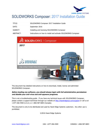
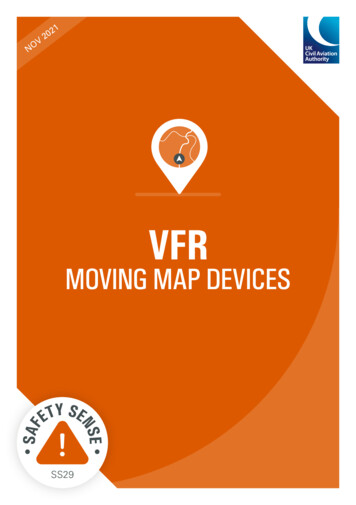
MMCPC for the FiAF Software Design Document, Version 1.03Fig. 1 Data flow among MMC-PC, MPS, and TAMMAC systems1.5 Design ApproachA primary MMCPC software design goal was to create an appearance and behavior similar to othercommon Windows-based products. The MMCPC functional diagrams (Figs. 2 through 4) were used tobuild a requirements matrix (Appendix A), which was redefined and expanded during a series of designreviews, and was subject to mutual approval by technical representatives from NRL, NAVAIR, and theFiAF.Procedures were developed to accommodate the final requirements matrix. Leveraging the FiAFexperience and familiarity with the original MMC software, MMCPC requirements were mapped, whenpossible, to existing MMC GUI components. The software development tool kit QT, which containstemplates for creating Windows-like applications, was used to design and create GUIs and generate C
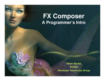
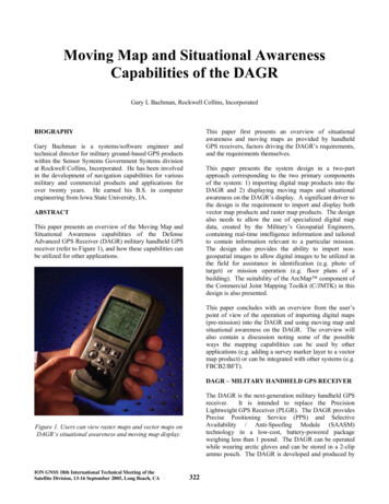
4Myrick et al.programming language code. Some Map Data Processing modules were written in C and later linked intoMMCPC as object libraries.Fig. 2 MMCPC data processing functional diagramFig. 3 MMCPC map composition functional diagram
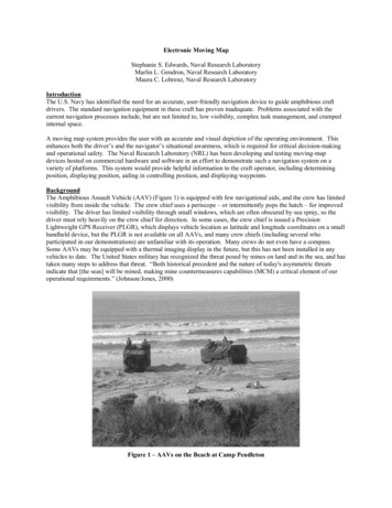
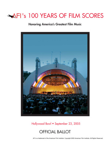
MMCPC for the FiAF Software Design Document, Version 1.05Fig. 4 MMCPC map data operations functional diagramGUI menus and options were created to provide the user with tools that are easy to use and facilitatethe required tasks. Each GUI option is linked to at least one matrix requirement (Appendix B). Shortcutsand hotkeys for GUI options are defined, as are actions, conditions, and usage cases (i.e., when the menuoption is available for use). Since a primary goal was to create a similar appearance and behavior foundin other commercial Windows-based software, comparable design conventions were followed andimplemented. For example, file browsers were designed to offer access to all valid storage devices anddirectory locations.2. MMCPC ARCHITECTUREThe MMCPC architecture supports the three primary tasks described above (data processing, mapcomposition, and map data operations) along with GUI communications and error checking functions.This section describes the design and implementation of each.2.1Data ProcessingThe first step in developing TAMMAC theater/mission data loads is to process any of several types ofsource data from FiAF or NGA (Table 1) into a TAMMAC-compatible format. NGA CADRG and CIBare already TAMMAC-compatible and require no MMCPC processing. The following sections of thisreport describe the three data processing functions provided in MMCPC to prepare the non-compatibledata types: Process FiAF source GeoTIFF files into the CADRG format (MIL-C-89038: NGA 1994).Regrid FiAF or NGA source DTED (MIL-PRF-89020A: NGA 1996) into RDTED.Reformat non-georeferenced images into HDF formatted data frame files (Harris 2002).
6Myrick et al.Table 1 Source Data for MMCPCSourceData TypeFiAFGeoTIFFFiAF & NGADigital Terrain and Elevation Data (DTED) - level 1 (100m)AnyData frames (TIF, GIF, PNG, BMP, JPEG, and HDF images)NGACompressed Arc Digitized Raster Graphics (CADRG)NGAControlled Image Base (CIB)2.1.1 FiAF GeoTIFF to CADRG ProcessingCADRG data is processed from source FiAF GeoTIFF data for use in the creation of TAMMACtheater and mission loads. Once processed, this data is available for use in other MMCPC compositions.Figure 5 provides an overview of CADRG processing, which includes five critical phases (color-codedconsistently throughout this section): 1) determine finalization status (blue); 2) validate directorystructure and source data (orange); 3) define destination path (green); 4) validate color palettes (yellow);and 5) process data (purple). Appendix C provides a full description of CADRG processing, includinglow-level steps within each phase.2.1.1.1 Determine CADRG Finalization StatusThe finalization procedure determines whether partial map segments (i.e., processed map files that arenot completely filled with map data) should be fully processed or should remain in a partial state untiladditional data is appended to the files. CADRG data processing begins in one of two initial states: 1) allprevious CADRG processed data has been finalized or 2) unfinalized CADRG data exists on the system.Processing is assumed to be in the first state when MMCPC is used to process FiAF GeoTIFF source filesinto CADRG. When unfinalized data are detected, MMCPC prompts the user to either finalize theremaining map files or append additional data.Data should not be finalized (see Section 2.1.1.5) when multiple sets of source GeoTIFF data (i.e.,multiple data CDs) are used until the last data set is loaded into MMCPC. This allows the user to processthe current set of source data and resume processing another time. Alternatively, data is finalized whenall source data is processed at once, from one source media; however, it cannot be appended later withadditional processed data.After MMCPC has determined the status of CADRG finalization, it defines the data source anddestination paths. If unfinalized data exists, the user may choose to either finalize the previous set of dataor append more map data to the previously processed data set. When the user chooses to append to thedata, the destination path for the newly processed data is automatically preset to the destination of theexisting data. If the existing processed data was finalized, then the user must define the path to the FiAFGeoTIFF source data and the destination path (Fig. 6).
MMCPC for the FiAF Software Design Document, Version 1.0Fig. 5 High-level flow chart for CADRG data processingFig. 6 Control flow for CADRG finalization phase7
8Myrick et al.2.1.1.2 Validate Source Directory Structure and Data for CADRG ProcessingAfter source and destination paths are set, MMCPC verifies the FiAF GeoTIFF directory structure(Fig. 7). If it is invalid, an error message is displayed, CADRG data processing halts, and MMCPCreturns to the main window. If the structure is valid, the header record of every GeoTIFF file in thedestination directory is read and verified (Fig. 8). If the source is on CD, the volume label must beFAF GTIF. A valid source includes a root directory, at least one subdirectory, and a TIF file. The sourcemust be 8-bit GeoTIFF; MMCPC does not yet support 24-bit GeoTIFF. MMCPC verifies that eachsource GeoTIFF longitude bound is within 3 of its original longitude to minimize geospatial processingerrors during transformation to CADRG. If the bounds are invalid, the steps are repeated until a validdirectory structure is passed or the operation is cancelled. See Section 2.5 for MMCPC error handling.Fig. 7 Source GeoTIFF directory structureFig. 8 Control flow for CADRG directory path and data validation phase2.1.1.3 Define CADRG Destination PathAfter the source FiAF GeoTIFF files have been verified, the destination path is created, if it does notalready exist (Fig. 9). The destination directory path provided by the user will be appended with a unique
MMCPC for the FiAF Software Design Document, Version 1.09MMCPC-assigned subdirectory path, or Processed Unique Identification (PUID), in the form ofCDRGFIAFxxxx s, where xxxx is a unique number (0001-9999) and s is a system identifier (A-Z)assigned by the MMCPC system administrator during installation. For example, if the user choosesdestination directory C:\MMCPC\Data\CDRG for the first FiAF geotiff data processed on the system,with an identifier of “A,” then the final path to the processed CADRG data will beC:\MMCPC\Data\CDRG\CDRGFIAF0001 A. Figure 10 gives an example of a full CADRGdirectory structure processed by MMCPC.Fig. 9 — Control flow for CADRGdestination path creationFig. 10 — CADRG data directory structureand file naming convention2.1.1.4 Validate Color PalettesEach map scale supported in CADRG uses a standard 8-bit color palette. During installation ofMMCPC, a default set of NGA color palettes is automatically loaded onto the system. This default set ofpalettes is also used to process FiAF geotiff into CADRG only if no custom color palettes are providedwith the geotiff. There is no need to maintain the default color palettes to use NGA CADRG incombination with processed FiAF CADRG. NRL recommends that FiAF operators use their own customcolor palettes for processing geotiff files into CADRG to improve color accuracy. The user may processmultiple data sets with different color palettes without making the previous map data obsolete.The format of the custom color palette file (PALETTE.TXT) is shown in Fig. 11. The first line ofthe file contains the number of colors in the palette (maximum 216). If the actual number of colorsdoes not match the first line, the file will be considered incorrect and the map data will not be processed.Each successive line after the first contains the text: “Set n r g b” where n is a sequential color identifierand r g b are the red, green, and blue values (from 0 to 255) of the color. Note that the “S” in “Set” mustbe capitalized. Each value is delimited by a single space.
10Myrick et al.Fig. 11 — FiAF custom color palette format and sample file with 154 colors (maximum 216)MMCPC CADRG data processing routines determine whether a custom color palette exists for eachscale of source GeoTIFF file (Fig. 12). When a custom color palette file is detected, it is compared to theinstalled color palette on MMCPC for that scale. If the color values of the two palettes are identical,processing proceeds normally. If a difference exists between the custom color palette and the MMCPCinstalled palette for one or more map scales, the user is notified that new color palette(s) will be installedfor those scale(s). The user must then decide to either cancel CADRG data processing or to proceed. Byproceeding, the user has decided to install all of the custom color palettes for that scale.If the current set of source GeoTIFF data is to be appended to the previous set of processed data, anadditional check is made to validate the color palettes. For append processing, any color palettesassociated with the source data must match the installed color palettes (by scale). All map scales musthave either default color palettes or custom color palettes that are identical to the ones already installed.If the color palettes aren’t identical, an error condition is detected, and CADRG data processing stops.Note: custom color palettes (and all associated actions) are not installed on the MMCPC system until dataprocessing actually begins.
MMCPC for the FiAF Software Design Document, Version 1.011Fig. 12 — Control flow for color palette validation2.1.1.5 Process CADRG DataAfter all color palettes checks are complete, the CADRG processing dialog box prompts the user forthe following information: Set Finalize Automatically (default yes): If all source data will be processed at once, from onesource media, this default setting will finalize the processed data and not allow any additional data tobe appended. This setting should be disabled (toggled to “no”) when multiple sets of source GeoTIFFdata (i.e., multiple data CDs) will be used, or when source data will be processed in multiple parts.Disabling this setting will allow the user to process the current set of source data and resumeprocessing later with no discontinuity. Set Delete Unfilled Segments (default no): Removes partially filled processed map files from thefinal processed CADRG. This option is not applicable if the preceding setting (Set FinalizeAutomatically) is disabled.
12Myrick et al. Descrip
Windows-based software application that provides data processing and mission/theater map data load support for the Tactical Aircraft Moving-Map Capability (TAMMAC) Digital Map System (DMS). This software release of MMCPC, in sole support of the FiAF F/A-18 program, contains sub-stantial software modifications to meet specific FiAF requirements.