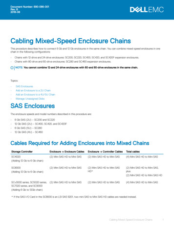
Transcription
Quick SAS Cabling GuideA Dell Technical White PaperPowerVault MD3200 and MD3200i Storage Arrays
Quick SAS Cabling GuideTHIS WHITE PAPER IS FOR INFORMATIONAL PURPOSES ONLY, AND MAY CONTAIN TYPOGRAPHICALERRORS AND TECHNICAL INACCURACIES. THE CONTENT IS PROVIDED AS IS, WITHOUT EXPRESS ORIMPLIED WARRANTIES OF ANY KIND. 2010 Dell Inc. All rights reserved. Reproduction of this material in any manner whatsoever withoutthe express written permission of Dell Inc. is strictly forbidden. For more information, contact Dell.Dell, the DELL logo, and the DELL badge, PowerConnect, and PowerVault are trademarks of Dell Inc.Other trademarks and trade names may be used in this document to refer to either the entitiesclaiming the marks and names or their products. Dell Inc. disclaims any proprietary interest intrademarks and trade names other than its own.July 2010Page ii
Quick SAS Cabling GuideContentsComponents of Dell PowerVault MD32xx/MD32xxi System . 2Supported System Configurations . 4Fault-tolerant Asymmetric Cabling Scheme . 5Simple Cascade Cabling Scheme . 5Diagrams . 5TablesTable 1.Supported System Configurations . 2.3.4.5.6.7.8.9.10.11.12.13.14.15.Simple Cascade Cabling Scheme: Configuration C01 . 6Simple Cascade Cabling Scheme: Configurations C02, C03 . 7Simple Cascade Cabling Scheme: Configurations C04, C05, C06 . 8Simple Cascade Cabling Scheme: Configurations C07, C08, C09, C10 . 9Simple Cascade Cabling Scheme: Configurations C11, C12, C13, C14, C15 . 10Simple Cascade Cabling Scheme: Configurations C16, C17, C18, C19 . 11Two Enclosures: Configurations C20, C21, C22 . 12Single Enclosure: Configurations C23, C24 . 13Fault-tolerant Asymmetric Cabling Scheme: Configurations C01 . 14Fault-tolerant Asymmetric Cabling Scheme: Configurations C02, C03. 15Fault-tolerant Asymmetric Cabling Scheme: Configurations C04, C05, C06 . 16Fault-tolerant Asymmetric Cabling Scheme: Configurations C07, C08, C09, C10 . 17Fault-tolerant Asymmetric Cabling Scheme: Configurations C11,C12,C13,C14,C15 . 18Fault-tolerant Asymmetric Cabling Scheme: Configurations C16, C17, C18, C19 . 19SAS Cable Labels . 20Page 1
Quick SAS Cabling GuideComponents of Dell PowerVault MD32xx/MD32xxi SystemThe following are the integral blocks of the Dell PowerVault MD32xx/MD32xxi storage array systems:1.2.3.4.5.MD3200 is the SAS RAID array residing in the enclosure with 12 horizontally positioned 3.5" disk slotsMD3220 is the SAS RAID array residing in the enclosure with 24 vertically positioned 2.5" disk slotsMD3200i is the iSCSI RAID array residing in the enclosure with 12 horizontally positioned 3.5" disk slotsMD3220i is the iSCSI RAID array residing in the enclosure with 24 vertically positioned 2.5" disk slotsMD1200 is the RAID array expansion residing in the enclosure with 12 horizontally positioned 3.5"disk slots6. MD1220 is the RAID array expansion residing in the enclosure with 24 vertically positioned 2.5" diskslotsMD3200 and MD3220 back view:NOTE:Only a single SAS or iSCSI RAID array mustbe present in the system.MD3200i and MD3220i back view:MD1200 and MD1220 back view:NOTE:This guide makes an assumption that theuser has MD32xx/MD32xxi system operatingin the duplex mode (the recommendedmode of operation), i.e. when both RAIDcontrollers are present and are fullyoperational.Front view of MD3200/MD3200i/MD1200 (top) and MD3220/MD3220i/MD1220 (bottom):Page 2
Quick SAS Cabling GuideMD32xx SAS RAID array has SAS RAID controllers (RCs):MD32xxi iSCSI RAID array has iSCSI RAID controllers (RCs):Array expansion enclosure has enclosure management modules (EMMs):Page 3
Quick SAS Cabling GuideSupported System ConfigurationsThe MD32xx/MD32xxi storage array system may consist of the following twenty four order independentcombinations of the enclosures with 12 horizontally positioned 3.5" disk slots and the enclosures with 24vertically positioned 2.5" disk slots.Table 1.Supported System ConfigurationsConfig.IDTotalNumber ofEnclosuresMaximumNumberof DisksNumber ofEnclosureswith 12Disk SlotsNumber ofEnclosureswith 24Disk SlotsC0189680(hyperlink)Figure 1(hyperlink)Figure 9C0279661(hyperlink)Figure 2(hyperlink)Figure 10C0378470(hyperlink)Figure 2(hyperlink)Figure 10C0469642(hyperlink)Figure 3(hyperlink)Figure 11C0568451(hyperlink)Figure 3(hyperlink)Figure 11C0667260(hyperlink)Figure 3(hyperlink)Figure 11C0759623(hyperlink)Figure 4(hyperlink)Figure 12C0858432(hyperlink)Figure 4(hyperlink)Figure 12C0957241(hyperlink)Figure 4(hyperlink)Figure 12C1056050(hyperlink)Figure 4(hyperlink)Figure 12C1149604(hyperlink)Figure 5(hyperlink)Figure 13C1248413(hyperlink)Figure 5(hyperlink)Figure 13C1347222(hyperlink)Figure 5(hyperlink)Figure 13C1446031(hyperlink)Figure 5(hyperlink)Figure 13C1544840(hyperlink)Figure 5(hyperlink)Figure 13C1637203(hyperlink)Figure 6(hyperlink)Figure 14C1736012(hyperlink)Figure 6(hyperlink)Figure 14C1834821(hyperlink)Figure 6(hyperlink)Figure 14C1933630(hyperlink)Figure 6(hyperlink)Figure 14C2024802(hyperlink)Figure 7(hyperlink)Figure 7C2123611(hyperlink)Figure 7(hyperlink)Figure 7C2222420(hyperlink)Figure 7(hyperlink)Figure 7C2312401(hyperlink)Figure 8(hyperlink)Figure 8C2411210(hyperlink)Figure 8(hyperlink)Figure 8Simple abling SchemeIllustrationPage 4
Quick SAS Cabling GuideFault-tolerant Asymmetric Cabling SchemeAlthough more complex to set up, the fault-tolerant asymmetric cabling scheme is the recommend way ofconnecting the expansion enclosures to the RAID array as it makes the enclosure loss protection possible.Enclosure loss protection is an attribute of a disk group. Enclosure loss protection guarantees accessibilityto the data on the virtual disks in a disk group if a total loss of communication occurs with a singleexpansion enclosure. An example of total loss of communication might be loss of power to the expansionenclosure or failure of both EMM modules. Naturally, the enclosure loss protection is not guaranteed if aphysical disk has already failed in the disk group. In this situation, losing access to an expansion enclosureand consequently another physical disk in the disk group causes a double physical disk failure and loss ofdata.Enclosure loss protection is achieved when you create a disk group where all of the physical disks thatcomprise the disk group are located in different expansion enclosures. This distinction depends on the RAIDlevel.For the diagram illustrating how to cable the specific configuration you have please see(hyperlink)Table 1Note: An incorrect SAS cabling will be detected by the array system. The MD32xx/MD32xxi Storage Managerwill warn you about the mis-wired enclosures by logging a major event in the event log. In addition, theRecovery Guru will point you to the mis-wire condition and provide you some guidance on correcting theproblem. Please remember that a mis-wire condition will only be reported if incorrectly plugged SAS cablesresult in a non-working configuration. In theory, it is possible to attach the expansion enclosures in atechnically correct manner, which will not be optimal but still be functional. The mis-wire events will notbe logged for a configuration of this type.Simple Cascade Cabling SchemeThe simple cascade cabling scheme could be used when the enclosure loss protection is not required.The advantage of using this scheme is the simplicity of the initial system set up.For the diagram illustrating how to cable the specific configuration you have please see(hyperlink)Table 1DiagramsThis section contains diagrams illustrating the MD32x/MD32xxi system configurations.The last diagram (hyperlink) Figure 15 contained in this section is a special case: it contains picture of thelabels which you can print, cut out and attach to the both ends of every SAS cable used in yourconfiguration for an easy identification. If after initial wiring your array system has to betransported/moved then the labeled SAS cables will simplify the task of re-assembling the system.Page 5
Quick SAS Cabling GuideFigure 1.Simple Cascade Cabling Scheme: Configuration C01Page 6
Quick SAS Cabling GuideFigure 2.Simple Cascade Cabling Scheme: Configurations C02, C03Page 7
Quick SAS Cabling GuideFigure 3.Simple Cascade Cabling Scheme: Configurations C04, C05, C06Page 8
Quick SAS Cabling GuideFigure 4.Simple Cascade Cabling Scheme: Configurations C07, C08, C09, C10Page 9
Quick SAS Cabling GuideFigure 5.Simple Cascade Cabling Scheme: Configurations C11, C12, C13, C14, C15Page 10
Quick SAS Cabling GuideFigure 6.Simple Cascade Cabling Scheme: Configurations C16, C17, C18, C19Page 11
Quick SAS Cabling GuideFigure 7.Two Enclosures: Configurations C20, C21, C22Page 12
Quick SAS Cabling GuideFigure 8.Single Enclosure: Configurations C23, C24Page 13
Quick SAS Cabling GuideFigure 9.Fault-tolerant Asymmetric Cabling Scheme: Configurations C01Page 14
Quick SAS Cabling GuideFigure 10.Fault-tolerant Asymmetric Cabling Scheme: Configurations C02, C03Page 15
Quick SAS Cabling GuideFigure 11.Fault-tolerant Asymmetric Cabling Scheme: Configurations C04, C05, C06Page 16
Quick SAS Cabling GuideFigure 12.Fault-tolerant Asymmetric Cabling Scheme: Configurations C07, C08, C09, C10Page 17
Quick SAS Cabling GuideFigure 13.Fault-tolerant Asymmetric Cabling Scheme: Configurations C11,C12,C13,C14,C15Page 18
Quick SAS Cabling GuideFigure 14.Fault-tolerant Asymmetric Cabling Scheme: Configurations C16, C17, C18, C19Page 19
Quick SAS Cabling GuideFigure 15.SAS Cable LabelsLabels for SAS Cables(Cut out the labels and attach them to the ends of the SAS -EMM1-INEE7-EMM1-OUTPage 20
Components of Dell PowerVault MD32xx/MD32xxi System The following are the integral blocks of the Dell PowerVault MD32xx/MD32xxi storage array systems: 1. MD3200 is