Transcription
Network Cabling DesignBest Practices: 20171056 Baker RoadDexter, MI 48130t. 734.408.1993
Network Cabling DesignBest Practices: 2017Installation:This whitepaper outlines the guidelines and best practices for the installation ofdata networking equipment. The information is mainly based on the experiencegathered from environmental assessments that were performed by Cisco personnelat customer sites around the world. It also covers a few installation requirements,which are already included in the product’s hardware installation guides, but areoften missed.The implementation of the installation requirements specified in the product’smanuals is mandatory for the proper functioning of Cisco data networkingequipment. The guidelines and best practices that are explained in this modulehelp improve operations by minimizing the risk of failure, increasing the meantime between failures (MTBF), reducing the installation time, and planning themaintenance costs.Page Index: Cabling, page 3 Electrostatic Discharge (ESD), page 18 Grounding, page 12Airflow, page 28Mechanical Assembly & PowerRedundancy, page 30Faceplates, page 31Optical Connectors & Ports, page 33Surge Protection, page 34Temperature & Humidity, page 38www.ctctechnologies.com2
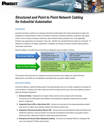
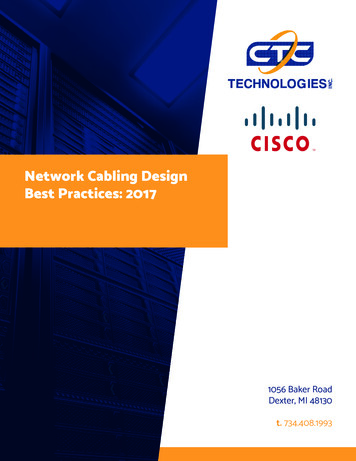
Network Cabling DesignBest Practices: 2017Cabling Guidelines, page 4 Best Practices, page 8Frequently Missed Requirements:The following are examples of requirements that are frequently missed in the field: Ensure that the cables are not installed in front of the air ventilation grids (as shown in Figure 2-1) as it leadsto improper ventilation, overheating of the equipment, and dust accumulation.Figure 2-1 Cables Obstructing the Air Grid on the side of a Cisco Data Networking Equipmentwww.ctctechnologies.com3
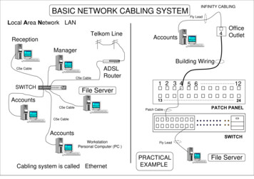
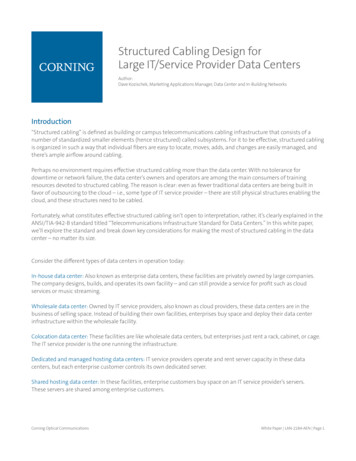
Network Cabling DesignBest Practices: 2017Guidelines For Fiber Cables, page 5 For Copper and Fiber Cables, page 6For Copper CablesThe following guidelines are recommended during the installation of copper cables: Avoid placing multiple cable bundles over each other, or over bundling the cables, as it leads to performancedegradation of the cables below. Ensure that the copper cables are twisted (as shown in Figure 2-2) together for canceling out ElectromagneticInterference (EMI) from the external sources that are not exposed even partially, as it results in EMI issues.Figure 2-2 Twisted Cable Avoid the following actions that can stress the cable:– Applying extra twists.– Pulling or stretching beyond the specified pulling load rate.– Creating tension in the suspension runs.– Stapling or applying pressure with the cable ties. Preserve the same density of twists in the cable pairs till its termination for horizontal and backbone twistedpair cabling as applicable. Avoid using patch cables, which are used to connect data networking equipment to patch panels that areconstructed using a solid core STP cable with stranded core RJ-45 connectors (as shown in Figure 2-3), becausethis can cause failure of the individual cables over a period of time due to connector differences and core size(with no metal to metal connection between the blades of the connector and the core of the cable). Even thoughconnectivity is initially established, the risk of failure increases due to the movement or flexing of cables and/orstress between the cable and connectors.www.ctctechnologies.com4
Network Cabling DesignBest Practices: 2017Guidelines, Cont.Figure 2-3 Patch Cables with Solid Core STP Cable and Stranded Core RJ45 Connectors - Offset of the Blades to the Side and Pushing of the Wireto the Opposite Side with the Solid Core WiringFor Fiber CablesThe following guidelines are recommended during the installation of fiber cables: Avoid the following actions that can stress the cable:– Pulling or stretching beyond the specified pulling load rate.– Bending it beyond the specified bend radius.– Creating tension in the suspension runs.www.ctctechnologies.com5
Network Cabling DesignBest Practices: 2017Guidelines, Cont.For Copper and Fiber CablesThe following guidelines are recommended during the installation of both copper and fiber cables: Separate the copper and fiber cables in the runs (or have separate runs) because the weight of thecopper cables can crush the fiber cables that are placed below it. Use cables that are resistive to bend loss if excessive bending of cables cannot be prevented due toinstallation constraints. Avoid mounting the cabling components in places that block accessibility to other equipment (such asa power strip or fans) in and out of the racks. Maintain extra cables for contingency needs as spares for the backbone and horizontal runs. Unless you are running the cables in an outdoor environment, ensure that appropriately sized conduits,cable raceways and/or ladders are used for future expansion. Label the cables with their destination at each and every termination point (to ensure that both the endsof the cable are labeled for identification and traceability). Test every cable during installation and termination. If a problem occurs, tag the malfunctioning cablesand separate them out. If applicable, locate the main cabling distribution area close to the central region of the installation siteto minimize the cable distances. Dedicate outlets for terminating horizontal cables, that is, assign a port in the patch panel for eachhorizontal run. Include sufficient vertical and horizontal runs when designing the cables. Otherwise, even a slightchange, such as the removal of a cable can cause downtime. Use the angled patch panels in high-density areas, such as the cable distribution area. Use the straightpatch panels in the distribution racks. Avoid exposing cables to areas of condensation and direct sunlight. Remove the abandoned cables, as they restrict the airflow, and contribute to the possible increase in theoperational temperatures, which can affect the durability of the system. Avoid routing the cables over equipment and other patch panel ports (as shown in Figure 2-4). Instead,route the cables below or above, and into the horizontal cable manager (if it is in place) (as shown inFigure 2-5 and Figure 2-6).www.ctctechnologies.com6
Network Cabling DesignBest Practices: 2017Guidelines, Cont.For Copper and Fiber Cables, Cont. If running cables in/out of a sealed outdoor cabinet, ensure that all the cable glands are sealed to preventdust and moisture from entering the box. For separation requirements of communications wires and electric power cables, refer to the NEC (NFPA 70)standard. As an example, see what is stated in Article 800.133 (2005 NEC):Communication wires and cables shall be separated at least 50 mm (2 inches) from conductors of anyelectric, power, Class 1, non-power limited fire alarm, or medium-power network-powered broadbandcommunication circuits.However, please check the national and local electrical codes and regulations, since they may overrule therequirements mentioned in this standard.Figure 2-4, Figure 2-5, Figure 2-6, and Figure 2-7 are examples of good and bad cabling practices.Figure 2-4 Improper CablingCausing IneffectiveOperations and Maintenancewww.ctctechnologies.comFigure 2-5 Proper Cabling7
Network Cabling DesignBest Practices: 2017Guidelines, Cont.Figure 2-6 Efficient Cablingwww.ctctechnologies.comFigure 2-7 Inefficient Cabling8
Network Cabling DesignBest Practices: 2017Best Practices, Cont.For Copper CablesThe following best practices are recommended during the installation of copper cables: Install higher cable categories to meet the application requirements that may arise in the future. Use thin and high-density cables as necessary to enable more cable runs in tight spaces. Use the Velcro-based ties every 1 to 2 meters for bundling or securing the cables, and avoid using zip ties as theyapply pressure on the cables.For Fiber CablesThe following best practices are recommended during the installation of fiber cables: Do not touch the fiber tips of fiber cables. Use single mode and multi-mode optical fiber cables as per the optical transceiver requirement.For Copper and Fiber CablesThe following best practices are recommended during the installation of both copper and fiber cables: Do not use copper and fiber cables whose connector retention tabs are broken. While inserting copper and fiber cables, check that the connector retention tab locks into the connector or theoptical transceiver properly. Use modular cabling systems to map the ports from equipment with high density port counts. Avoid leaving loose cables on the floor, as this could constitute as a major safety hazard. Instead, use the vertical,horizontal, or overhead cable managers. Store a few spare patch cables. The type and quantity of the patch cables can be determined from the installationand projected growth. Ensure that all the unused cables are stored in a bagged and capped condition when notin use. Use the patch cable of exact length, and leave some slack at each end for end device movements. Use vertical and horizontal cable guides for routing cables within and between the racks. Use cable spool devices in the cable managers to prevent kinks and sharp bends in the cable. Bundle the related cables together in groups (for example, bundle the ISL cables and uplinks to their core devices),as this eases management and troubleshooting. Regularly maintain the cabling documentation, labeling, and physical or logical cabling diagrams. Document and regularly update all the cabling components and their mapping.www.ctctechnologies.com9
Network Cabling DesignBest Practices: 2017Best Practices, Cont. For new installations or re-cabling of the existing equipment, install the cable guides to reduce mechanicalstress and bending of the data cables, and to enhance the maintainability. Figure 2-8 shows an example of therecommended cable guides for the Cisco Catalyst 6500 chassis. The installation and usage of cable guidesshould be independent of the number of cables that are installed. However, there are products that do not usecable guides, or where the cable guides cannot be installed. For more information on the cable guides, see theinstallation guides that support specific Cisco data networking equipment.Figure 2-8 Examples of Recommended Cable Guides for the Cisco Catalyst 6500 Chassiswww.ctctechnologies.com10
Network Cabling DesignBest Practices: 2017Best Practices, Cont. Cable guides are particularly useful because excessive bending of the interface cables damages them. Figure 2-9shows an example of an efficient way of cabling using the cable guides.Figure 2-9 Efficient Cabling using Cable GuidesFigure 2-10 Bend Radius - Examplewww.ctctechnologies.com11
Network Cabling DesignBest Practices: 2017Grounding Guidelines, page 16 Best Practices, page 17IntroductionGround (earth) refers to the reference point in an electrical circuit from which other voltages are measured, or acommon return path for an electric current, or a direct physical connection to the Earth.Electrical circuits are connected to the ground (earth) for several reasons. For example, in equipment that ispowered by the mains, the exposed metal parts are connected to the ground to prevent the user from coming intocontact with dangerous voltage if an internal fault, such as an insulation failure occurs. Furthermore, connectionsto the ground also prevent the buildup of static electricity.Frequently Missed RequirementsThe following are examples of requirements that are frequently missed in the field: Equipment racks are not connected to the installation site or the building ground. Equipment managers shouldensure that all the equipment racks are grounded to the building. If this is not done, there can be a serious safetyrisk to the personnel, since they could assume that the equipment is properly grounded when it is actually not.Additionally, an electrical discharge can cause operational deficiencies or expose the data networking equipmentto the risk of permanent failure due to ESD risk.NOTE:One of the initial instructions in Cisco installation guides is to ground the rack. Because there are different lawsand legislations in different countries, this activity is usually performed by qualified electricians that have theproper instrumentation to help them test the effectiveness of the rack grounding.Figure 2-11 depicts the grounding cable that is not connected to the grounding bar of the installation site.www.ctctechnologies.com12
Network Cabling DesignBest Practices: 2017Frequently Missed Reqs.Figure 2-11 Rack Grounding Cable notConnected to the Grounding BarIn addition to rack grounding, many Cisco data networkingdevices require the installation of an NEBS (NetworkElectrical Building System) compliant ground, and theyhave dedicated grounding points for this purpose.This is because a system that uses only an AC thirdprong ground is not sufficient to fully ground the device.Electrostatic discharge (ESD) can lead to the followingfailures: Damage to electronic components Data corruption System lockup Frequent system rebootsSome service technicians claim that they do not need NEBS grounding as they rely on metal-to-metalconnections between the Cisco device and rack. First of all, even if the metal-to-metal connectivity seemsproperly in place, you need to use a multi-meter to verify the effectiveness of the connectivity. For example,the use of plastic screws and washers to minimize vibrations avoids effective metal-to-metal connections. Youneed to use a multimeter to verify the effectiveness of the metal-to-metal connectivity. For example, the useof plastic screws and washers to minimize vibrations avoids effective metal-to-metal connections.In addition, even though the multimeter confirms good connectivity, you cannot trust the metal-to-metalconnection between the equipment and the rack over the time, since the connection may not work properlyanymore. For examp
Use the patch cable of exact length, and leave some slack at each end for end device movements. Use vertical and horizontal cable guides for routing cables within and between the racks. Use cable spool devices in the cable managers to prevent kinks and sharp bends in the cable.