Transcription
AT&T IP Flexible Reach ServiceNortel BCM 200/400 (Release 4.0.2.03a) Configuration GuideAT&T VOIPNortel BCM 200/400 (Release 4.0.2.03a)Configuration GuideFor Use with AT&TIP Flexible Reach ServiceIssue 1.23/02/2007Issue1.2Page 1 of 30
AT&T IP Flexible Reach ServiceNortel BCM 200/400 (Release 4.0.2.03a) Configuration GuideTABLE OF CONTENTS12345Introduction. 41.1Document Change History. 4Special Notes . 5Overview. 6Configuration Guide . 84.1Nortel BCM Version and Feature Requirements. 84.2VOIP Gateway Trunks. 104.3H.323 Gateway Parameters. 154.4Media Parameters. 164.5Port Ranges . 174.6Configuring Outgoing Calls from BCM to AT&T IP Flex Reach . 184.7Configuring Incoming Calls from AT&T IP Flex Reach to BCM . 194.8Configuring IP Phone LCD Screen to Display DID Number. 20Troubleshooting . 215.1System Monitoring with BCM Monitor . 215.2Real-time BCM System Status LED Displays. 245.3Real-time BCM Fault/Alarms Management. 255.4BCM Service Management System . 265.5BCM Log Management . 28Issue1.2Page 2 of 30
AT&T IP Flexible Reach ServiceNortel BCM 200/400 (Release 4.0.2.03a) Configuration GuideTABLE OF FIGURESFigure 1: AT&T IP Flexible Reach Network . 6Figure 2: BCM 200/400 software version . 8Figure 3: Software Management Menu . 9Figure 4: Patch List. 9Figure 5: Available VOIP Gateway Trunks. 11Figure 6: Assigning DN numbers to Line Pool . 12Figure 7: Defining Route for VOIP Trunks. 13Figure 8: Assign Destination Code to Route Numbers. 14Figure 9: H.323 Gateway Parameters . 15Figure 10: Media Parameters . 16Figure 11: Media Gateway Port Range. 17Figure 12: Configuring DID for Outgoing Calls . 18Figure 13: Configuring DID for Incoming Calls . 19Figure 14: Displaying DID Number on IP Set LCD. 20Figure 15: System Monitoring Example. 21Figure 16: IP Device Listing. 22Figure 17: RTP Session Information . 22Figure 18: Line Monitor Information . 23Figure 19: System Resources. 23Figure 20: Front Panel LED Display . 24Figure 21: Real-time BCM 200/400 Alarm Display. 25Figure 22: BCM Service Manager Screen . 26Figure 23: Log Management Screen. 29Issue1.2Page 3 of 30
AT&T IP Flexible Reach ServiceNortel BCM 200/400 (Release 4.0.2.03a) Configuration Guide1 IntroductionThis document provides a configuration guide to assist Nortel Networks BCMadministrators in connecting to AT&T IP Flexible Reach service.1.1 Document Change HistoryIssue 1.0Issue 1.101-03-2007; first general release02-05-2007;1) modified section 4.2 for clarity of IP trunks and linepool configuration.2) Added CCG disclaimer statement at end of document.3) Modified cover page.Issue1.2Page 4 of 30
AT&T IP Flexible Reach ServiceNortel BCM 200/400 (Release 4.0.2.03a) Configuration Guide2 Special NotesEmergency 911/E911 Services LimitationsWhile AT&T IP Flexible Reach services support E911/911 calling capabilities incertain circumstances, there are significant limitations on how these capabilitiesare delivered. Please review the AT&T IP Flexible Reach Service Guide in detail tounderstand these limitations and restrictions.Failover to an Alternate AT&T Border Element Not SupportedBCM does not support failover to an alternate AT&T Border Element. BCM mustbe configured to send to one specific border element.Unattended Call Transfers are not supportedAn unattended transfer is one in which the recipient of the transfer has notanswered the phone prior to the transfer. This type of transfer is not supportedwith BCM and the AT&T Network. For example, if a call with the AT&T network istransferred by BCM phone 1 to BCM phone 2, phone 2 must answer prior to thecompletion of the transfer by phone 1.Fax Limitations T.38 fax is not currently supported with the IP Flexible Reach service IP Flexible Reach service supports fax using G.711; however, this is notsupported by the BCM 200/400 today when configured to use G.729 asthe first preferred codec. There is an issue where the BCM does notautomatically detect fax/modem tones and switching the call to G.711. To work-around this limitation; the BCM supports fax by usinganalog/POTS lines to the PSTN. BCM-GATM-8 or BCM-GATM-4 media baymodules are required to interface with analog/POTS lines.Issue1.2Page 5 of 30
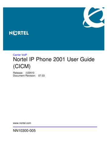
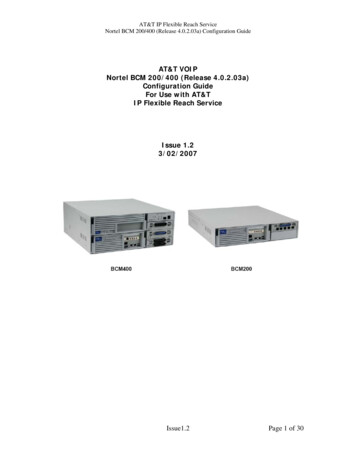
AT&T IP Flexible Reach ServiceNortel BCM 200/400 (Release 4.0.2.03a) Configuration Guide3 OverviewThis section provides a service overview of the Nortel Business CommunicationManager 200/400 (BCM 200/400) IP PBX integration with AT&T IP Flexible Reachservice. For an overview of Nortel BCM 50 for IP Flexible Reach; pleasereference a separate document named “Nortel BCM 50 Configuration Guide.”PSTApplicationServerCall ControlElementNetworkGatewayBorderElementAT&T ManagedWithVoice GWLegacyCircuitPBXPublic SidePrivate SideSwitchAT&TManagedRouterWith NATIP BorderElementNortel BCM 200/400Figure 1: AT&T IP Flexible Reach NetworkThe Nortel BCM customer premises site shall consist of the followingcomponents. Nortel IP 2004 or IP 2002 phones – These phones use the Nortelproprietary UNIStim signaling protocol to communicate to the Nortel BCM200/400 IP PBX for call feature and routing support. These phones can beconnected to a Nortel Ethernet switch (ES 470, ERS 5520, etc.) thatsupplies in-line power (IEEE 802.3af) to the phones.Issue1.2Page 6 of 30
AT&T IP Flexible Reach ServiceNortel BCM 200/400 (Release 4.0.2.03a) Configuration Guide NorteloooooooBCM 200/400 IP PBX – This unit consists of the following.Media Service Card (MCS) ProcessorTwo ports Ethernet / IP cardIntegrated CallPilot voice mail systemAnalog station ports for connection to fax machines.Digital station ports for Norstar digital phonesT1 voice card for connection to the local PSTN.GATM-8 analog trunk to PSTN for inbound/outbound faxThe following routing scenarios are supported by the Nortel BCM IP PBX and DONOT use the AT&T Call Control. Local Nortel BCM phone to local Nortel BCM phoneLocal fax machine to other fax machine via PSTNThe following routing scenarios are supported by the BCM IP PBX and DO usethe AT&T Call Control. For voice calls, the G.729 codec shall be used. Nortel BCM phones to PSTN (domestic US and international).Nortel BCM phones to legacy PBX site with Cisco gateway.Legacy PBX site with Cisco gateway to Nortel BCM phones.Nortel BCM phones at one Nortel BCM IP PBX site to Nortel BCM phonesat another Nortel BCM IP PBX site.If the customer has subscribed to Calling Plans B and C (Local), then thefollowing routing scenarios are supported by the BCM IP PBX and DO use theAT&T Call Control. For voice calls, the G.729 or G.711 codec may be used. BCMselects G.729 as the highest priority codec. Inbound PSTN to BCM phoneOutbound local PSTN calls from the BCM phones.Outbound local N11 (i.e. 411, 911) calls from the BCM phones.Issue1.2Page 7 of 30
AT&T IP Flexible Reach ServiceNortel BCM 200/400 (Release 4.0.2.03a) Configuration Guide4 Configuration GuideThis configuration guide specifies the Nortel BCM 200/400 screens that must beconfigured and updated to support the AT&T IP Flexible Reach service.4.1 Nortel BCM Version and Feature RequirementsThe Nortel Networks BCM must be running release 4.0.2.03a. You can check theversion of BCM by viewing the following screen.Figure 2: BCM 200/400 software versionEnsure that the System Identification page specifies Version 4.0.2.03a. This isthe supported release that is required for AT&T IP Flexible Reach service.Issue1.2Page 8 of 30
AT&T IP Flexible Reach ServiceNortel BCM 200/400 (Release 4.0.2.03a) Configuration GuideThe following BCM 4.0 patches must be applied. To verify installed/appliedpatches; from the BCM Element Manager’s main menu, select “Administration”then: Software ManagementÆ Software Update HistoryFigure 3: Software Management MenuPatch escriptionIVR Provider UpdateLAN CTE Client UpdateIPTEL Provider Agent and FEPS UpdateCTI Update1.1-1.01.0-1.0Element Manager UpdatePSM UpdateFigure 4: Patch ListIssue1.2Page 9 of 30
AT&T IP Flexible Reach ServiceNortel BCM 200/400 (Release 4.0.2.03a) Configuration Guide4.2 VOIP Gateway TrunksVoice over IP (VoIP) lines are signaling channels that simulate how CO lineswork. However, VoIP lines transmit data to the IP network over a LAN or IPnetwork rather than over physical lines. Once the VoIP trunks are set up, youcan assign them to line pools, and program their behavior in the same way youwould PRI lines.VoIP trunks use line numbers 001 to 060. To view these line records selectConfiguration -- Telephony -- Lines -- Active VoIP Lines. To access VoIPlines, you need to enter software keycodes. Each keycode supports a specificnumber of trunks. The H.323 trunks start numbering up from 001. No entriesappear in the Enabled VoIP lines field until you complete the IP Trunks Settingsfield, which displays when you select IP Trunks under Configuration -- Resources -- Telephony Resources -- IP trunks.VoIP trunks should be configured to use a single line pool per VoIP trunk type.Do not mix other trunk types on the same line pool. The VoIP line pools areassigned to routes, which in turn, are configured with destination codes thatroute calls to the AT&T IP Flex Reach network.You can also create a fallback for the trunk. This is a situation where the systemreroutes the call to a PSTN line pool if the primary route is not available or thecall quality is not suitable. If you do not configure your network for fallback andthe call quality is below threshold, the IP call fails.Issue1.2Page 10 of 30
AT&T IP Flexible Reach ServiceNortel BCM 200/400 (Release 4.0.2.03a) Configuration GuideCheck under Configurations - Lines- Active VOIP Lines to see if Trunkshave been allocated (See Figure 5 below). You should have a number of VOIPgateway trunks displayed. The total number of lines indicated corresponds tothe number of IP trunks licensed by Nortel for your BCM. In this case we showeight active trunks.Figure 5: Available VOIP Gateway TrunksIssue1.2Page 11 of 30
AT&T IP Flexible Reach ServiceNortel BCM 200/400 (Release 4.0.2.03a) Configuration GuideFor each IP trunk you must select a Line Pool in the “Details” tab at the bottomof the page (See Figure 6 below). Available Pool codes start at A to O. In thiscase we selected “Pool O.” Additionally, the Line Pool needs to be associatedwith all DN’s that require access to the VOIP trunks. Go to ConfigurationsÆTelephonyÆ Dialing PlanÆ Line Pools to perform this configuration.Figure 6: Assigning DN numbers to Line PoolIssue1.2Page 12 of 30
AT&T IP Flexible Reach ServiceNortel BCM 200/400 (Release 4.0.2.03a) Configuration GuideUnder Configuration Æ Telephony Æ Dialing Plan Æ RoutingÆRoutes tabwe need to define a “Route” for each pool (See Figure 7 below). In our case wedefined Route 001. We also need to assign “Pool O” to this particular route andconfigure the route for “National” numbering dial plan type.Figure 7: Defining Route for VOIP TrunksIssue1.2Page 13 of 30
AT&T IP Flexible Reach ServiceNortel BCM 200/400 (Release 4.0.2.03a) Configuration GuideUnder Configuration Æ Telephony Æ Dialing Plan Æ Routing (See Figure 8below), under the “Destination Codes” tab we need to associate the Route to thedesired access code. Configure this to access code “9” or to whatever code youwant to access for outside (IP off-net) call that will be presented to the AT&Tservice for routing. In this case, when “9” is dialed we wish to push the dialedstring to the IP trunk for routing.Figure 8: Assign Destination Code to Route NumbersIssue1.2Page 14 of 30
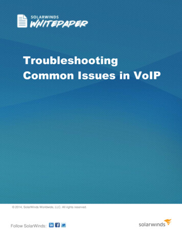
AT&T IP Flexible Reach ServiceNortel BCM 200/400 (Release 4.0.2.03a) Configuration Guide4.3 H.323 Gateway ParametersConfigurationÆ Telephony ResourcesÆ IP TrunksÆ On this screen we need to populate the Call Signaling as“GatekeeperRoutedNoRAS”Alias Name: The AT&T IP Flexible Reach service does not require aH.323 ID name. However, the BCM was tested with a H.323 ID name andNortel recommends that the customer provides a meaningful name in thisfield.H.245 tunneling must be enabled.For the Call Signaling Port use 1720 as a value.Make sure the Primary Gatekeeper IP is populated with the correctAT&T IPBE IP address. Sample IP addresses are shown next.o Primary Gatekeeper – (please contact your Customer CareRepresentative for the AT&T IP border element IP address)o Backup Gatekeeper – 0.0.0.0*Figure 9: H.323 Gateway Parameters*Note: the backup gatekeeper will not be supported on the current BCM 200/400release. The Nortel backup implementation is not compatible with the IP FlexibleIssue1.2Page 15 of 30
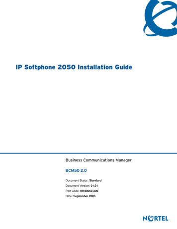
AT&T IP Flexible Reach ServiceNortel BCM 200/400 (Release 4.0.2.03a) Configuration GuideReach service today. Nortel will provide support in a future release. In case offailure to the primary gatekeeper; the BCM will not be able to place any outgoingcalls to the AT&T IP Flexible Reach service. The backup gatekeeper IP address(Please contact your Customer Care representative) must be manually configuredin the “Primary Gatekeeper IP” field to restore outgoing calls. Additionally,the AT&T IP Flexible Reach service will send incoming calls to the BCM frommultiple IP border elements. The BCM will accept calls from any border elementswithout additional configuration.4.4 Media ParametersConfigurationÆ ResourcesÆ Telephony ResourcesÆ IP Terminal GlobalSettingsWithin the Media Parameters tab; ensure that all values are exactly as thesample screen shot shown below: 1st Preferred Codec:G.729Silence Compression: DisabledJitter Buffer – Voice: AutoT.38 Fax Support:DisabledG.729 Payload Size:20Figure 10: Media ParametersIssue1.2Page 16 of 30
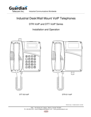
AT&T IP Flexible Reach ServiceNortel BCM 200/400 (Release 4.0.2.03a) Configuration Guide4.5 Port RangesConfigurationÆ ResourcesÆ Port Ranges ÆUse the values shown below. The default ranges are from 28000 to 28511. Thisrange is used for fax, digital phones and analog phones. The media gatewayport ranges are configurable.Figure 11: Media Gateway Port RangeThe BCM IP phone’s RTP and RTCP port range are 51000-51399. Each IP phonecall uses two ports. The default port range for RTP and RTCP are notconfigurable.Issue1.2Page 17 of 30
AT&T IP Flexible Reach ServiceNortel BCM 200/400 (Release 4.0.2.03a) Configuration Guide4.6 Configuring Outgoing Calls from BCM to AT&T IP Flex ReachConfigurationÆ Telephony Æ Active Sets ÆFirst locate the desired private DN number that you want to assign the publicDID number under the “Line Access” tab. In this case we have selected “DN3000”. At this point, select the “Properties” tab under the “Details” window.We will now associate the private DN number with the DID number. In theexample below; 3000 is entered in the “Private OLI” field and 7323683476 isentered in the “Public OLI” field. This example enables “calling numbertranslation” (outgoing) for this particular DN number.Figure 12: Configuring DID for Outgoing CallsIssue1.2Page 18 of 30
AT&T IP Flexible Reach ServiceNortel BCM 200/400 (Release 4.0.2.03a) Configuration Guide4.7 Configuring Incoming Calls from AT&T IP Flex Reach to BCMConfigurationÆ Telephony Æ Active Sets ÆWe will now configure the “called number translation” (incoming) for the DNnumber. First locate the desired private DN number that you want to assign thepublic DID number under the “Line Access” tab. In this case we have selected“DN 3000”. At this point, select the “Line Assignment” tab under the“Details” window. Enter 3000 in the “Private Received” number field; thenenter the 10 digit DID (Public number) in the “Public Received” number field.With the BCM 4.0 release; incoming DID calls will be routed to telephones, basedon all 10 digits received by the network. For example, Incoming calls from theAT&T IP Flexible Reach network will deliver a ten digit DID number, e.g.7323683476. The BCM will route the call using all ten digits, e.g. 7323683476.Figure 13: Configuring DID for Incoming CallsIssue1.2Page 19 of 30
AT&T IP Flexible Reach ServiceNortel BCM 200/400 (Release 4.0.2.03a) Configuration Guide4.8 Configuring IP Phone LCD Screen to Display DID NumberConfigurationÆ Telephony Æ LinesÆ Target LinesÆ Line 241To display the DID number on the IP phone LCD screen; select Line 241 than goto the “Parameters” tab. In our example below, enter 3683476 in the “Name”field and then select “public” as the line type from the drop down menu.Figure 14: Displaying DID Number on IP Set LCDIssue1.2Page 20 of 30
AT&T IP Flexible Reach ServiceNortel BCM 200/400 (Release 4.0.2.03a) Configuration Guide5 TroubleshootingThis section provides some tips about troubleshooting problems5.1 System Monitoring with BCM MonitorA valuable application for performance monitoring is the BCM Monitor. It allowsthe BCM administrator to see the current status of various parts of the BCMsystem. Statistical information is provided on system throughput and otherperformance-related information, including system CPU usage (graph or tableformat) and memory usage (graph or table format).If a performance display is active, it is automatically updated with real-timeperformance information in user-selectable time increments.The focus of the real-time monitoring capabilities is: Overall system statusUtilization of resources on the Media Services Card (e.g. signaling channelusage)Operation of telephony applications (e.g., Messaging, Call Center, etc.).IP telephony activityD-channel monitoring for PRI, BRI and VoIP trunksFigure 15: System Monitoring ExampleIssue1.2Page 21 of 30
AT&T IP Flexible Reach ServiceNortel BCM 200/400 (Release 4.0.2.03a) Configuration GuideThe BCM Monitor application can be downloaded to an administrator’s PC fromthe BCM and pointed at a specific BCM’s IP address for monitoring. Multipleinstances of the BCM Monitor application can be used on a single PC to monitorseveral remote BCM systems at the same time.Backward version compatibility is supported.All of the registered IP devices can be viewed with the BCM Monitor. The screenshot below depicts IP Phone type, DN number and IP address of each registeredIP phone. Additionally, if the device is active on a call the RTP sessioninformation is also displayed.Figure 16: IP Device ListingThe end-to-end RTP sessions per IP call can also be displayed with the BCMManager. The example below depicts an end-to-end call.Figure 17: RTP Session InformationIssue1.2Page 22 of 30
AT&T IP Flexible Reach ServiceNortel BCM 200/400 (Release 4.0.2.03a) Configuration GuideThe BCM Monitor can be used to monitor incoming and outgoing trunks todetermine if trunks are being busy or if they are idle. The example below depictsutilized lines used by local and remote telephone/DN numbers.Figure 18: Line Monitor InformationThe BCM Monitor can also be used to monitor all types of system usages. Thefollowing are some parameters that can be monitored: CPU utilization Physical memory Media card DSP utilization IP sets and IP Trunks Voice ports and media gateway usageFigure 19: System ResourcesIssue1.2Page 23 of 30
AT&T IP Flexible Reach ServiceNortel BCM 200/400 (Release 4.0.2.03a) Configuration Guide5.2 Real-time BCM System Status LED DisplaysAdministrationÆ System LED Status ÆThe BCM 200/400 front panel LED displays can be viewed remotely to determinecertain critical components. The following are some LED indications that can beviewed remotely with the NCM Unified Manager: PowerHard drive (HDD)Multi-service Card (MSC)ModemEthernet ports (NIC)System temperatureFan indicationsFigure 20: Front Panel LED DisplayUsing the Element Manager “System Status” tab, you can monitor overall systemperformance and other performance-related information. You monitor systemstatus using the following tools: LED StatusQoS MonitorUPS StatusNTP MetricsInterface MetricsDisk MirroringQoS MetricsIssue1.2Page 24 of 30
AT&T IP Flexible Reach ServiceNortel BCM 200/400 (Release 4.0.2.03a) Configuration Guide5.3 Real-time BCM Fault/Alarms ManagementYou can view and manage real-time alarms generated by the BCM system.Alarms arise from components that are running on the system; these alarmsindicate faults or informational conditions that may require resolution from thesystem administrator. Examples of alarm conditions include: T1 circuit on the system is downService running on the BCM has been stopped by an administratorAlarm information can be delivered to you by any of the following means: The Alarms Panel in the BCM Element ManagerThe Alarm Banner in the BCM Element ManagerCore telephony alarms show on the alarm setSimple Network Management Protocol (SNMP) traps for remotemanagement of faultsLEDs on the BCM main unitBelow is an example of the BCM Alarms Panel in the BCM Element Manager:Figure 21: Real-time BCM 200/400 Alarm DisplayYou can manage alarms and alarm information by: Configuring alarm settings, for example filtering alarms so that only thedesired subset of alarms are displayed in the BCM Element ManagerAlarms Panel or sent as SNMP trapsAdministering alarms, for example acknowledging selected alarms andclearing the alarm logIssue1.2Page 25 of 30
AT&T IP Flexible Reach ServiceNortel BCM 200/400 (Release 4.0.2.03a) Configuration Guide5.4 BCM Service Management SystemYou can view details about the services that run on the BCM system, including: The name of a serviceWhether a service is enabled to automatically start upThe status of the service running on the BCMYou can also administer services by starting, stopping, and restarting certainservices.Caution: Use the BCM Services Manager only as directed by Nortel TechnicalSupport. Improper use of the BCM Services Manager may adversely affectsystem operation.Figure 22: BCM Service Manager ScreenYou can stop any of the services that are running on the BCM system.To stop a service Click the Administration tab.Open the General folder, and then click the Service Manager task.The Service Manager page opens. Services are displayed in the Servicestable.In the Services table, select a service.Issue1.2Page 26 of 30
AT&T IP Flexible Reach ServiceNortel BCM 200/400 (Release 4.0.2.03a) Configuration Guide Click the Stop button. A confirmation dialog box opens.Click Yes. In the Services table, Stopped is displayed in the Statuscolumn for the stopped service.To restart a service Click the Administration tab.Open the General folder, and then click the Service Manager task. TheService Manager page opens. Services are displayed in the Servicestable.In the Services table, select a stopped service.Click the Restart button. A confirmation dialog box opens.Click Yes. In the Services table, Running is displayed in the Statuscolumn for the restarted service.Issue1.2Page 27 of 30
AT&T IP Flexible Reach ServiceNortel BCM 200/400 (Release 4.0.2.03a) Configuration Guide5.5 BCM Log ManagementAnother extremely useful tool is the “Log Management.” This allows you toquickly and easily collect all relevant logs files and other information to help thevarious support teams debug any problems you may have with your BCM200/400. The entire log files required to diagnose a problem is consolidated intoa single file.A log file is a collection of individual log events generated by the BCM. Anadministrator can use log files to monitor and analyze system behavior, usersessions, and events. You manage log files by transferring selected BCM logarchives from the BCM to a specified location, such as your personal computer.You can then view individual log events using the BCM Element Manager LogBrowser or your usual text editor.Note: Depending on the privileges assigned to you, you may or may not see allthe log files or processes described in this section.In addition to the log files generated by the BCM, the Element Manager itselfgenerates a log file. This log is found under the Help selection of the BCMElement Manager Toolbar. This log contains diagnostic information.The BCM manages log archives and maintains generations of informationdepending upon size or other criteria. Generations of log files have a numberedextension such as 3.gz.A generation of the “alarms.systemlog” file is created each time the BCM isrebooted or when the log file reaches the 1 MB limit.Transferring and Extracting Log FilesYou use the BCM Element Manager to transfer log files from the BCM to anexternal location. You must transfer the log files to an external device before youcan view them. If you are using the BCM Element Manager Log Browser to viewthe logs, you will also have to extract the log files from the log archive that istransferred from the BCM. The log archive contains a collection of log files.When you transfer the log archives to another device, you can specify: The location to which you want to transfer log files, such as your personalcomputer or a network folderIssue1.2Page 28 of 30
AT&T IP Flexible Reach ServiceNortel BCM 200/400 (Release 4.0.2.03a) Configuration Guide The category of logs you want to transfer, such as Sensitive InformationlogsA schedule for a log file transferYou can also transfer log files using the BCM Web page if you cannot access theBCM Element Manager. After you transfer the log archives, several options areavailable to you for extracting the log file information and for viewing the logfiles. If you are using the BCM Element Manager (recommended), the LogBrowser prompts you to extract the actual log files from the .tar file. If youprefer, you can use the WinZip application to expand the .tar file into its includedlog files. As an alternative to using the BCM Element Manager Log Browser, youcan use an application such as WordPad to view the log files.Using the BCM Element Manager Log Browser to view extracted log files givesyou the ability to view information in a way that suits you; for example, you canfilter and sort information according to priority, time, message, and so on.Figure 23: Log Management ScreenWhen you first suspect a problem with your BCM, it is important that you go intothe “Log Management” screen and download the log file to your PC. Even if youend up resolving the issue, it is good to know that this information has beencaptured.Issue1.2Page 29 of 30
AT&T IP Flexible Reach ServiceNortel BCM 200/400 (Release 4.0.2.03a) Configuration GuideThis Customer Configuration Guide ("CCG") is offered as a convenience toAT&T's customers. The specifications and information regarding the product inthis CCG are subject to change without notice. All statements, information, andrecommendations in this CCG are believed to be accurate but are presentedwithout warranty of any kind, express or implied, and are provided “AS IS”.Users must take full responsibility for the application of the specifications andinformation in this CCG.In no event shall AT&T or its suppliers be liable for any indirect, special,consequential, or incidental damage
AT&T IP Flexible Reach Service Nortel BCM 200/400 (Release 4.0.2.03a) Configuration Guide . 4.2 VOIP Gateway Trunks . Voice over IP (VoIP) lines are signaling channels that simulate how CO lines work. However, VoIP lines transmit data to the IP network over a LAN or IP network rather than over physical lines. Once the VoIP trunks are set up, you