Transcription
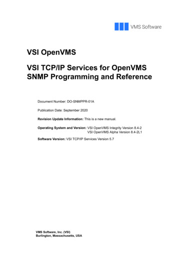
INSTALLATION INSTRUCTIONS& MAINTENANCE GUIDEMODEL N, VSI, IVSI & ZCSINGLE WALL, DOUBLE WALL AIR &CERAMIC FIBER INSULATED POSITIVE PRESSURE PIPING SYSTEMS BOILER STACK ENGINE EXHAUST GREASE DUCTA MAJOR CAUSE OF CHIMNEY RELATED FIRESIS FAILURE TO MAINTAIN REQUIREDCLEARANCES (AIR SPACES) TO COMBUSTIBLEMATERIALS. IT IS OF UTMOST IMPORTANCETHAT THIS CHIMNEY BE INSTALLED INACCORDANCE WITH THESE INSTRUCTIONS.www.ampcostacks.com 800.669.3269
Table of ContentsA - General InformationSafety PrecautionsFeaturesUnderwriters Laboratories ListingsApplicationsUse of Individual PartsSurroundings / EnclosureMulti-Engine ExhaustsPart NumbersClearancesOuter Pipe Surface TemperaturePipe Joint AssemblySealant UsagePipe WeightSupport MethodsVertical Support and Guide SpacingE – Roof & Wall PenetrationsRoof Support Assembly (P-MRS)Ventilated Roof Thimble (P-MVT)Flashings & Storm Collar333344445567778232326F – Terminations, Drains, Pressure ReliefExit Cone (P-EC)27Closure Ring (P-CR)27Stack Cap (P-SK)27Drain Section (P-DS)27Termination Height28Flange Adapter (P-FD)28Boiler Kit Adapter (P-BK)29Seal Ring (P-SR)29Excessive Pressure Relief Valve 30(P-ER)(Corrosion Protection: Exterior Pipe & Supports)Thermal ExpansionChimney Guying & SpacingSeismic Requirements9910B - Fittings45 Lateral Tee (P-JL)90 Tee (P-MT)Drain Tee Cap (P-TC)Thermal Expansion Lengths90 Wye (P-JY)Stepped Increaser (P-OS)Tapered Increaser (P-OT)ElbowsUse of Elbows, Offsets w/ Manifolds111111111212121213C – Adjustable & Thermal ExpansionFittingsBellows Expansion Joint (P-BJ)Adjustable Expansion Length (P-AG)Non-Exp Variable Length (P-VL)Short & Odd Lengths15161818D – Structural Support & GuidingPlate Support Assembly (P-PA)Clamp Flange (P-CF)High Strength Plate SupportWall Support Assembly (P-WA)Wall Guide Assembly (P-WG)Floor Guide (P-FG)Full Angle Ring (P-FR)19192020202222G – Grease DuctListingsSurroundsClearancesSlopeJoint Assembly (regular pipes & adjustables)SealantMaintenance & SafetyAutomatic CleaningFire SuppressionHood TransitionCleanout Tee Cap (P-TCN)Fan Adapter (P-FA)Fan Adapter Termination (FAT)Roof Support Section (RSS)Through Penetration Firestop (TPF)No-Tool Access Cap (P-NTAC)Field Installed Access CapConnecting to Rectangular DuctsInline Access DoorSample Drawings3132323233333434343535353535373839394041H – Type B Gas VentInstallation Instruction Supplementfor Type B Gas Vent432
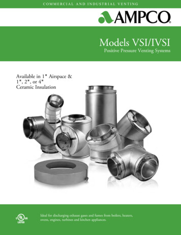
Installation InstructionsSection AGENERAL INFORMATIONSAFETY PRECAUTIONSAPPLICATIONSBuilding Heating Appliance Chimney Listing - Under thiscategory (UL 103, ULC-C959), Model VSI and IVSI have beendetermined suitable for venting flue gases at a temperature notexceeding 1000 F, under continuous operating conditions, fromgas, liquid and solid fuel fired appliances. Intermittent operation(less than one hour) at temperatures not exceeding 1400 F, andbrief (maximum 10 minute) operation at temperatures notexceeding 1700 F, is also permitted under this application.! WARNINGFailure to follow these Installation Instructions could causeFIRE, CARBON MONOXIDE POISONING, OR DEATH.If you are unsure of Installation requirements, call thePhone Number listed on the front of these instructions.Caution-Risk of injury. Sheet metal parts may besharp. Always wear gloves and appropriate eye, foot, andother protection when handling these products.Building Heating Appliance Chimney (Type HT) Listing Under this category (UL 103HT), the 5” through 24” ID ModelIVSI has qualified for UL’s additional, optional “Type HT”rating (for Building Heating Appliance Chimneys) whichindicates they have been evaluated and found suitable forexposure to 2100 F flue gases for a 10 minute duration at 2”airspace clearance to combustibles (unenclosed). Many local,state and regional code authorities require a “Type HT” rating forchimneys for certain appliance venting applications; especiallysolid fuel.Building Heating Appliance Chimneys are suitable foruse with Building Heating Appliances and other Low HeatAppliances as described in the Chimney Selection Chart ofNational Fire Protection Association (NFPA) Standard No. 211.Follow these instructions carefully. Failure to followthese instructions could result in an unsafe installation. If you areunsure of any instructions contact the factory at the numberindicated on the front page of these instructions.A major cause of chimney/duct related fires is failure tomaintain required clearances (airspace) to combustible materials.It is of utmost importance that this product be installed only inaccordance with these instructions.Reference Combustion & Ventilation Air on page 30 forproper air supply guidelines.FEATURESModel N, VSI and IVSI products are cylindrical, prefabricated,modular venting systems incorporating flanged joints, designedfor both quick assembly and pressure sealing capability. ModelN is single wall vent. Model VSI is of double wall constructionincorporating a 1” airspace between walls and Model IVSIincorporates 1” to 4” thick ceramic fiber insulation. Theircircular cross section and high quality stainless steel inner wallconstruction provide for a system with high strength-to-weightratio and low friction losses.1400 F Chimney Listing - Under this category (UL 2561,ULC-C959), Model VSI and IVSI have been determined suitablefor venting flue gases continuously at a temperature notexceeding 1400 F, and a 10 minute intermittent service attemperatures not exceeding 1800 F. As such, Model VSI andIVSI are suitable for use with ovens and furnaces as described inthe Chimney Selection Chart of NFPA No. 211, in addition toother Applications.UNDERWRITERS LABORATORIES LISTINGSAmpco single wall Model N (aka VSI-I) and double wall modelsVSI (aka VSI-II) and IVSI venting systems are Listed byUnderwriters Laboratories, Inc. (UL) under UL File MH6673 inthe following product categories and in the diameters indicated:Model N (Single wall pipe) (aka VSI-1)Grease Duct for Restaurant Cooking AppliancesChimney Liner – Gas/Oil- UL 1777Chimney Liner for Existing Masonry & FactoryBuilt Chimneys- ULC S635Low Temperature Venting System, Type L (L-Vent) Listing Under this category (UL 641), 5” through 24” ID Model IVSIhas been determined suitable for use with gas and oil fueledappliances Listed as suitable for venting with Type L or Type Bventing systems. This qualifies the system for handlingcontinuous flue gas temperatures at a maximum of 480 F aboveambient, and permits full enclosure in combustible chaseconstruction, assuming the specified minimum airspaceclearance-to-combustibles is maintained.5” - 48”ID5”- 48” ID5” - 48”IDGrease Duct for Commercial Cooking Appliances Listing Applications and instructions for this category (UL 1978) arecovered in Section “G” entitled “Grease Duct”.Model VSI (Double wall, 1” air insulation) (aka VSI-II)Building Heating Appliance Chimney5”- 48” ID1400 Fahrenheit Chimney5”– 48”IDGrease Duct for Restaurant Cooking Appliances 5” - 48”IDBased upon the above referenced UL Listings and supplemental,UL confirmed pressure testing, Model VSI and IVSI are alsosuitable for use as complete exhaust systems for diesel engineand gas turbines. When Model VSI/IVSI is used as an engine orturbine exhaust it is intended to be installed in accordance withNFPA 37 “Stationary Combustion Engines and Gas Turbines”.This code states, “When such (flue gas) temperatures do notexceed 1000 F (538 C) except for infrequent, brief periods, theengines shall be classified as low heat appliances”. Forcontinuous operation over 1000 F and not exceeding 1400 F theexhaust system should be installed as a 1400 F Chimney.Model IVSI (Double wall, 1, 2, 3 or 4” thick fiber insulation)Building Heating Appliance Chimney5”- 48”ID1400 Fahrenheit Chimney5”–48” IDBuilding Heating Appliance Chimney(Type HT) 5”- 24”IDLow Temperature Venting System, Type L5” - 24”IDGrease Duct for Restaurant Cooking Appliances 5” - 48”IDFor Zero clearance grease duct applications (model IVSI-Z3 &IVSI-Z4) see Section G, “Grease Ducts”.3
Model IVSI may be used to meet various needs, such as:a) Reduce outer pipe surface temperature.b) Reduce building heat gain by retaining energy inside theduct.c) Increase the efficiency of energy recovery systems byreducing exhaust gas temperature losses.d) Increase chimney or exhaust system draft loss performancedue to reduced exhaust gas temperature drop.e) Reduce building noise levels caused by high speed orpulsating exhaust induced noise. NOTE: Specific tests havenot been conducted to measure acoustic performance.USE OF INDIVIDUAL PARTSThese instructions comprise both general guidelines and specialrequirements for all parts in the product line. Before specifying adesign or beginning an installation please carefully review theseinstructions.SURROUNDINGS / ENCLOSUREAmpco Model N, VSI and IVSI chimneys are primarilyintended to be used in fire resistive, noncombustiblesurroundings or installed unenclosed. Except as noted elsewherein these instructions, they are not intended for use in one or twofamily residences. (CAUTION — Do not enclose these systemsin a chase or passageway of ordinary wood or other combustiblematerial, unless noted as acceptable elsewhere in theseinstructions for a specific application.)For Type L Vent installations, Model IVSI may beenclosed within a chase fabricated from combustible buildingmaterials. Check local codes to determine the required firerating, if any, for such chase enclosures.Where the chimney extends through any zone of abuilding (outside that in which the heating appliance connectedto it is located), it shall be provided with an enclosure having afire resistance rating equal to or greater than that of the floor,ceiling, wall or roof assemblies through which it passes.Model VSI and IVSI Chimney may penetrate a combustible roofusing either the Roof Support Assembly (P-MRS) or theVentilated Roof Thimble (P-MVT). These are the only partsintended for use with combustible construction. All other parts,such as Plate and Wall Supports, and Floor and Wall Guides, arefor attachment to non-combustible construction.Where, according to local code, no chase enclosure isnecessary, Model VSI and IVSI may be placed adjacent to wallsof combustible construction at the minimum clearance specifiedon each pipe section and in the individual Listing; seeCLEARANCES section and Tables A-1a through A-1d. Contactlocal building or fire officials about restrictions and installationinspection requirements in your area.Model VSI and IVSI exhaust systems are intended for use inconnecting the heating appliance, engine, or turbine to theoutdoors, while operating under positive forced draft, negativeinduced draft or neutral gravity flow internal pressure conditions.Model VSI and IVSI (all insulation thicknesses) may beintermixed in the same chimney system, assuming the properassociated airspace clearances-to-combustibles are maintained.Complete system sizing and capacity information may beobtained from the “Chimney, Gas Vent, and Fireplace Systems”chapter of the ASHRAE Handbook, or by contacting AmpcoTechnical Support. In spite of these general sizing guidelines, itis most important that the heating appliance, engine or turbinemanufacturer’s installation instructions are followed. Notfollowing the equipment manufacturer’s instructions may resultin inadequate chimney performance and/or a violation of theequipment manufacturer’s installation requirements.ADDITIONAL APPLICATIONSModel N, VSI & IVSI are also suitable for negative, neutral orpositive pressure pre-fabricated piping systems intended for usein a variety of applications including but not limited to thefollowing: Fume Venting, Chutes, Particle Conveying, DryerVents and Ventilation Ducts.SUITABLE FOR POSITIVE PRESSURE VENTINGAPPLICATIONS WITH MAXIMUM 60" WATER COLUMNINTERNAL STATIC PRESSURE AT 1000 DEGREES F.MULTI-ENGINE EXHAUSTSA common exhaust system for multiple engine or turbineinstallations is generally not recommended. Check with yourengine or turbine manufacturer prior to common exhaust systemdesign. Exhaust gas from operating units tends to flow to nonoperating units where condensation may form. Water in engineor turbines at start-up may cause damage. In general, a separateexhaust system should be provided for each engine or turbine.CREOSOTE AND SOOT – FORMATION AND NEED FORREMOVALWhen wood is burned slowly, it produces tar and otherorganic vapors, which combine with expelled moisture to formcreosote. The creosote vapors condense in the relatively coolchimney flue of a slow-burning fire. As a result, creosote residueaccumulates on the flue lining. When ignited this creosote makesan extremely hot fire.The chimney should be inspected at least once every 2months during the heating season to determine if a creosote orsoot buildup has occurred; if creosote or soot has accumulated, itshould be removed to reduce the risk of chimney fire.Refer to Elbow & Offset section for additionallimitations with regards to burning solid fuel.PART NUMBERSThese instructions identify major Model N, VSI and IVSI partsby name or part number. Actual parts always carry a prefix toindicate internal diameter. IVSI also includes a suffix to indicateinsulation thickness. For example: 24VSI-42 is a 24 inchdiameter of model VSI, 42 inches in length; 24IVSI-42C2 is a 24inch diameter section of Model IVSI, 42 inches long having 2inches of fiber insulation between the walls.4
CLEARANCESVenting CategoryType L VentMaximumContinuousFlue Gas Temp480 F overambient1,000 FTable A-1: Model IVSI-C2, Z3, C4, Z4Min. Airspace Clearance-to-Combustible ConstructionPipe I.D. Type Building Heating 1,400 F GreaseLApplianceChimneyDuctVentChimney(1,000 �A36”4”4”A42-48”5”5”AType ClearanceEnclosed*Building HeatingUnenclosed*Appliance Chimney(BHA)B.H.A Chimney (Type 1,000 FUnenclosed*HT)(IVSI 5”-24”)1,400 F Chimney1,400 FUnenclosed*Grease Duct500 FUnenclosed*0” from liner to masonryChimney Liner –1200 FinteriorULC S635(all fuel)1” from liner to masonryChimney Liner –570 F (gas/oil)interior & 1” from masonryexterior to combustibles**UL 1777* See Section Entitled “Surroundings/Enclosure”A See Section “G” Entitled “Grease Duct”For non-combustible construction, maintain clearances asrequired for installation, access for inspection or per local code.** Masonry chimney construction & surroundings must comply with NFPA 211OUTER PIPE SURFACE TEMPERATUREAs an aid for estimating expected outer wall surfacetemperatures, fiber insulated Model IVSI has been tested in avertical configuration using input energy levels consistent with“UL 103; Standard for Chimneys, Factory-Built, ResidentialType and Building Heating Appliance”. Testing with 1, 2 and 4inch insulation thicknesses resulted in development of Chart A-1and Table A-2, indicating the maximum expected outer surfacetemperatures. Compared to vertical configurations, horizontalconfigurations of Model IVSI will have lower surfacetemperatures due to a higher convective heat transfer coefficient. Thus, for horizontal configurations, Chart A-1 andTable A-2 are acceptable to use as they will give conservativeanswers. The Tables in A-2 give the same results as Chart A-1for the indicated outer pipe surface temperature, flue gastemperature and pipe size at an ambient temperature of 70 F.The chart can also be used for other operatingconditions. For example, at an actual flue gas operatingtemperature of 400 F (corresponding to a flue gas temperaturerise of 330 F at an ambient temperature of 70 F), all diametersof Model IVSI would require 1 inch of insulation to maintain theouter surface temperature below 140 F.Note: These tests were all conducted in accordancewith UL-103 in a vertical configuration with 1000 F flue gasesand air surrounding the pipe. Appreciable higher outer wallsurface temperatures would have been reached if insulation hadbeen placed around the outer wall of the pipe.Do not wrap or place insulation around these systemsin an effort to reduce clearances to combustibles, create sometype of fire protective enclosure or for any purpose, unlessAmpco has reviewed the practical engineering feasibility of suchapplication. Ultimately, the Authority Having Jurisdiction willneed to approve any Ampco engineering judgment that is offeredsince this is not been UL tested and listed.Table A-1a: Model NMin. Airspace Clearance-to-Combustible ConstructionSee Section “G”, Grease Ducts, or local code for other singlewall usesTable A-1b: Model VSIMin. Airspace Clearance-to-Combustible ConstructionBuilding HeatingTypeAppliance1,400 FGreasePipe I.D.LChimneyChimneyDuctVent(1,000 ATable A-1c: Model IVSI-C1Min. Airspace Clearance-to-Combustible ConstructionBuilding HeatingTypeAppliance1,400 F GreasePipe I.D.LChimneyChimneyDuctVent(1,000 ��5”5”A42-48”6”6”AA See Section “G” Entitled “Grease Duct”5
PIPE JOINT ASSEMBLYAll flange-to-flange inner pipe joints are identical (except forAdjustable Lengths, Variable Lengths and Lined Bellows Joints),thus eliminating special orientation for correct use. Assembly isaccomplished as follows: (See Section G for Grease Duct Connection)1. Parallel flanges are brought together (See Fig A-1).2. Sealant is applied to the groove of the inner “V” Band. Referto SEALANT USAGE section for proper sealant selection.3. The inner “V” band is then tightly clamped around theflanges using end clamp hardware. NOTE: Light tappingwith a wooden or similar mallet all around the band whiletightening the clamp helps to align and pull the flangestogether (See Fig A-1).4. (For Model IVSI only) insert strip of insulation (supplied) inarea of V-band, around entire circumference of assembly.Position insulation to insure no void spaces remain (See FigA-2).5. The outer channel band is then installed by inserting theedges of the band into the outer pipe grooves and drawing itclosed with the screws and nuts. For vertical exterior jointsapply sealant to the joint between the Channel Band and theouter pipe (See Figs. A-2 & A-3). *For horizontal/slopingChart A-1: Model VSI and IVSI Estimated Maximum OuterPipe Temperature Rise above Ambient Temperature6"-36" Dia.36" Dia.200VSI6" Dia.MODELSurface Temperature Rise ( F Above 00IVS1I-C36" Dia.I VS6" Dia.2I-C36" Dia.C4V SIEL I7008009006" Dia.1000Flue G as Temperature Rise ( F Above Ambient)Table A-2a: Required Insulation thickness for 120 F Surface TempIVSI Duct DiameterFlue Temp6”12”24”36”1000 F900 F800 F44700 F44600 F444500 F2444400 F1222300 F1111exterior joints, it is recommended to apply sealant (P-600) to bothsides of the Channel Band (top side is sufficient (9 o’clock to 3o’clock position)) with nut/bolt connection pointing downCaution-Risk of injury. Sheet metal parts may be sharp.Always wear gloves and appropriate eye, foot, and otherprotection when handling these products.Fig. A-1 – Pipe Joint AssemblyPipe FlangeSealantPipe OuterTable A-2b: Required Insulation thickness for 140 F Surface TempIVSI Duct DiameterFlue Temp6”12”24”36”1000 F44900 F44800 F444700 F4444600 F2244500 F1222400 F1111300 F1111Vee BandFig. A-2 – Pipe Joint AssemblyInsulation(IVSI Only)Table A-2c: Required Insulation thickness for 160 F Surface TempIVSI Duct DiameterFlue Temp6”12”24”36”1000 F444900 F800 F700 F600 F500 F400 F300 F442211144221114422111ntSeal a4442211ChannelBand6
Fig. A-3 – Assembled Model IVSI JointPIPE WEIGHTThe approximate weight of the pipe in lbs. per foot is equal to itsMultiplier multiplied by its inside diameter (in inches). See chartbelowWeight of PipeModelMultiplierN0.5Example:VSI0.936”IVSI-C1 weighsIVSI-C11.1approximately 36 x 1.1 IVSI-C21.339.6 Lbs/Ft.IVSI-C41.7IVSI-Z31.7IVSI-Z42.0INN ER PIPEINSULATIONOUTER PIPEUSE P-600 HEREON OUTDOOR VERTICALINSTALLATIONSINNER VEE BANDU SE A PPROPRIATE SEALA NT1/4" DEEP INV EE BAND GROOVEOUTER CHANNEL BANDSee Section Gfor grease ductjoint connectionSUPPORT METHODSVertical Installations require one of following methods ofsupport.Refer to the corresponding section for properinstallation instructions.1. Pier or Appliance outlet (See Section B for details)2. Base supported tee (See Section B)3. Plate Support Assembly (P-PA) (See Section D for details)4. Roof Support Assembly (P-MRS). (See Section F for details)5. Wall Support Assembly (P-WA) (See Section E for details)6. Fan Adapter Termination (FAT) (See Section G for details)7. Roof Support Section (RSS) (See Section G for details)USE P-600 ON BOTHSIDES FOR OUTDOORHORIZ/SLOPED INSTALLSSPACERFLANGED INNER JOINTSCAUTIONSA. THE OUTER CHANNEL BANDS ARE DESIGNED TOSLIDE IN THEIR MATING GROOVES. DO NOTATTACH BY SCREWS INTO THE OUTER CASING.B. DO NOT ALLOW SCREWS TO PENETRATE THEINNER PIPE. THIS CAN CAUSE CORROSION, GASLEAKAGE OR EXPANSION FAILURE.C. NEVER USE SCREWS THROUGH THE OUTERJACKET OF AN ADJUSTABLE LENGTH OREXPANSION JOINT.Table A-3, (Support Methods & Height Limits), shows themaximum height limits for each support method.Full Rings (P-FR) are used in vertical installations aswall guides to maintain proper alignment of the system and arefor lateral support for wind loads. Proper spacing of full ringguides and supports must be maintained. Requirements can befound in Table A-4, (Vertical Support & Guide Spacing), underthe columns designated “S-V”.The vertical freestanding height above the roof or topguide is limited due to wind considerations. The limitations for“Free Standing Height”, can be found in Table A-4 under thecolumns designated “F”. The table includes height limits for allvertical support methods based on model designation anddiameter.Horizontal installations or horizontal portions of verticalinstallations are supported primarily by use of Half Rings (P-HR)or Support Straps (P-SS) that are installed using minimum ½”threaded rod or structural steel provided by other. See Table A-5for maximum spacing between horizontal supports. PlateSupports (P-PA) are also used to support and stabilize the systemat changes in direction. For further details on the use of the PlateSupports, see section D.SEALANT USAGE1. Part No. P-600 (Dow Corning 700 is one of our ULapproved sealants): a silicone sealant UL listed for flue gastemperatures up to 600 F. Also used for weathering/sealingon outdoor seams & Channel Bands where necessary.2. Part No. P-2000: a high temperature pre-mixed sealant forflue gas temperature up to 2000 F. P2000 IS WATERSOLUBLE AND SHOULD NOT BE USED WHEREEXPOSED TO WEATHER.Sealant Coverage(Expected Number of Joints Sealed per Tube)Inner Dia.# of 4”526-28”430-32”336”242-48”17
Table A-3 Support Methods and Height LimitsPier or Appliance Outlet Sizes 5 thru 48” ¹Base Supported Tee 2Plate Support Assembly: Sizes 5”- 10”Sizes 12”- 16”Sizes 18”- 20”Sizes 22”- 28”Sizes 30”- 36”Sizes 38”- 48”Plate Suppt Ass’y w/ High Strength Base(See Fig. D-3): Sizes 5”- 10”Sizes 12”- 16”Sizes 18”- 20”Sizes 22”- 28”Sizes 30”- 36”Sizes 38”- 48”Roof Support AssemblyWall Support Assembly: Sizes 5”- 10”Sizes 12”- 16”Sizes 18”- 20”Sizes 22”- 28”Sizes 30”- 36”Sizes 38”- 48”Fan Adapter Termination, Roof Suppt SectFull Angle Ring, Guy Section, Wall Guide,Floor GuideNotes:1.2.Parts UsedP-CF & P-BKP-MT & ’135’108’96’75’56’IVSI-C4, ��475’375’300’257’200’150’P-PA (field mod)375’280’155’120’450’NAP-PA (field mod)P-PA (field mod)P-PA (field mod)P-PA (field mod)P-PA (field mod)P-MRSP-WAP-WAP-WAP-WAP-WAP-WAP-FAT, P-RSSP-FR, P-GS, PWG, ��17’40’20’15’13’30’Models Z3 & Z4 Only – See Table G-3See Table A-4: Dimension S-V(See Fig. A-6, A-7, A-8, D-6 for examples)NANANANANANANANANANANANAPier or appliance must be able to support pipe weight (and guy loads, if any) regardless of maximum height.For supporting structure used below Tee fitting, but in general, base supported tees are the least desirable option. P-MT and P-JL withintegral internal stiffener posts are available for increasing base supported tee heights. Consult factory for details.Table A-4Vertical Guide Spacing Support & Free Standing LimitsDia. VSI & IVSI-C1IVSI-C2IVSI-C4, Z3 & Z4Model ’8”12’8”6’4”23’10” NA617’6”8’9”15’10” 7’11”13’4”6’8”23’4” �3”23’2” NA1019’4”9’8”17’10” 8’11”15’6”7’9”23’2” NA1220’4”10’2” 18’10”9’5”16’8”8’4”23’9” NA1421’2”10’7” 19’10” 9’11”17’10”8’11”24’2” ’6”24’2” 25’9” �5” NA2224’10” 12’4”23’8” 11’10”22’11’27’1” 6”27’1” 10”28’4” 4”28’11” NA30 27’-10” 13’10” 26’10” 13’5”25’4”12’8”29’9” NA3228’6”14’3”27’8” 13’10”26’4”13’2”30’3” NA3630’15’29’2”14’7”27’10” 13’11”31’8” NA4226’6”13’3” 25’10” 12’11” 24’10”12’5”27’9” NA4823’11’6”22’8”11’4”21’10” 10’11” 23’11” NAS-V Maximum spacing between two guides or a support and a guide in avertical position.F Maximum height above a guide or support for free standing system abovea roof or parapet wall.8Table A-5: S-HHorizontal Support SpacingHalf Rings (P-HR), Full Rings (P-FR) &Support Straps (P-SS)VSI &IVSIIVSIModelDia.IVSIC4, Z3-C2NC1& ’10’17’26”-48”11’9’7’11’EXTERIOR CORROSION PROTECTION:IT IS RECOMMENDED TO APPLY ANEXTERIOR GRADE HIGH HEAT PAINT TOANY PLATE SUPPORTS, FULL/HALFANGLE RINGS, WALL SUPPORTS/GUIDES,ALUMINIZED OUTER WALLS &ROOF/WALL FLASHING COMPONENTS,EXPOSED OUTDOORS TO ENSUREMAXIMUM CORROSION PROTECTIONAGAINST THE ELEMENTS. (Ex. RustoleumV2100 series High Heat Industrial Aerosol)
THERMAL EXPANSIONGood installation practice requires that any length ofexhaust system between two fixed points subject to more than1/4 inch expansion must have an Adjustable Length (P-AG) orBellows Joint (P-BJ) to compensate for expansion. VSI/IVSI willexpand approximately 1 inch for every 100 F temperature riseper 100 feet of pipe.For Grease Duct applications any length over 12 feetinstalled between two fixed points i.e.: Hood Outlet and Elbow,Plate and Wall Support, etc., must be provided with anAdjustable Length (P-AG) to compensate for expansion andcontraction.It is essential that these parts be properly installed andprovided with adequate guidance to prevent binding or excessivebending forces. (See detailed installation information containedin Section C, Thermal Expansion.)The exhaust system designer must be aware that theinner joints have negligible flexing capability, and in addition,Tees and Elbows are not designed to withstand excessivebending forces. Because the amount of outer casing axialmovement is less than the inner casing movement, but stillsignificant, the outer jackets of piping and Adjustable Lengthsmust also slide to avoid excessive forces on Tees, Elbows orFixed Joints. To accommodate outer casing movements, externalguides along walls, at floors, or in lateral breechings, must allowfor movement of the pipe. Further; Full/Half Rings, Wall Guidesor Floor Guides must be so located that Outer Channel Bandmovements will be away from the ring.installation, contact the factory for complete guy tension andpreload calculations.The purpose of guying or bracing is to prevent windeffects from developing excessive bending forces or horizontaldisplacements in exposed chimneys. This means that cableswhich are attached to the guy section must be slightly slack orloose, allowing for thermal expansion to occur without damagingfasteners or attachments. Some stack configurations requirespring loaded Guy Tensioners (P-GT) to preload the guy cablesfor a satisfactory installation (See Fig. A-9). These displacementlimiting tension devices must be incorporated in cable guys ifexpected thermal expansion exceeds allowable slack in thecables.For stack heights above the roof requiring guy wires orrigid bracing to minimize thermal expansion effects, a PlateSupport Assembly (P-PA) or Wall Support Assembly (P-WA)must be installed at or near the roof line. If necessary, GuyTensioners should be used.The height limit of a Model VSI/IVSI stack above theroof can vary depending on the Stack Support involved (seeTable A-3) and whether the stack is welded, braced or guyed.Using the Roof Support (P-MRS), the maximum height allowedis dependent on size as indicated in Fig. A-6 and itsaccompanying Table A-4For stacks greater than those specified for single GuySection configurations (See Fig. A-6) such as two level guyingor those that will be located in severe weather locations, awelded Model IVSI assembly is recommended. The availabilityof multi-level guying (as shown in Fig. A-7) depends on windload, height, pipe diameter and material thickness. Not allmultilevel guying height and diameter combinations are possible.Contact the factory for a detailed design of welded multi-guyedModel VSI/IVSI stacks.CHIMNEY GUYING AND BRACINGModel N, VSI, IVSI, Z3 & Z4 Grease Duct has thinpipe walls relative to its diameter (t/D 0.006 for all sizes) andhas the characteristics of a continuous pipe of 300 SeriesStainless Steel. Therefore it will expand and contract along itsentire length with changes in temperature. Thus, unless properlyFig A-4. Guy Section details and cable attachmentssupported and guided, structural damage to the exhaust systemwill occur. For these reasons, conventional methods of attachingguides and braces to the outer pipe cannot be used. Correctlyinstalled Angle Rings (P-FR and P-HR), Wall Guides (P-WG),Floor Guides (P-FG), Guy Sections (P-GS), Plate SupportAssemblies (P-PA) and Wall Support
Model N, VSI and IVSI products are cylindrical, prefabricated, modular venting systems incorporating flanged joints, designed for both quick assembly and pressure sealing capability. Model . Chimney Liner - Gas/Oil- UL 1777 5"- 48" ID Chimney Liner for Existing Masonry & Factory-Built Chimneys- ULC S635 5" - 48"ID