Transcription
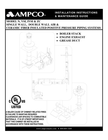
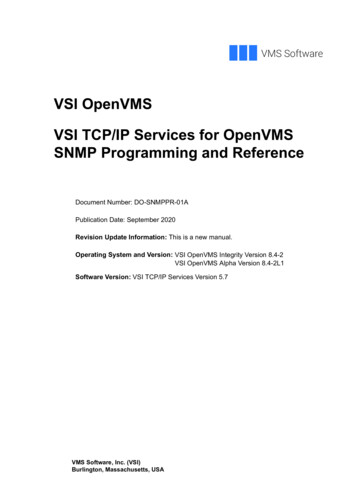
Com m erci a l a n d I n dust r i a l V en t i ngModels VSI/IVSIPositive Pressure Venting SystemsAvailable in 1" Airspace &1", 2", or 4"Ceramic InsulationIdeal for discharging exhaust gases and fumes from boilers, heaters,ovens, engines, turbines and kitchen appliances.
table of contentsUNDERWRITERS LABORATORIES LISTINGSModel VSI and IVSI in sizes 5” through 48” diameters havebeen tested and Listed (Safety Certified) by UnderwritersLaboratories, Inc. (ULI) and bears the UL and/or c-UL logosignifying compliance with U.S. and/or Canadian standards.UL Listing product categories e Duct (UL1978)Building Heating Appliance Chimney (UL103)(Industrial) 1400 F Chimney (UL2561)Type L Vent (Model IVSI only) (UL641)Type B Gas Vent (UL441)CanadaGrease Duct (UL1978)540 C (1000 F) Industrial Chimney (ULC-S604)760 C (1400 F) Industrial ChimneyCODE AND STANDARD COMPLIANCENFPA (NFPA 31, 37, 54, 96, 211)ICC (IMC, IFGC)IAMPO (UMC)Model VSI and IVSI have been approved by the Cityof New York Department of Buildings, Materials andEquipment Acceptance Division under the followingMEA numbers:Model VSIModel IVSIBuilding HeatingAppliance Chimney MEA 132-90M MEA 135-90M1400 F ChimneyMEA 133-90M MEA 181-90MGrease DuctMEA 134-90M MEA 134-90MSystem Concept . . . . . . . . . . . . . . . . . . . . . . 1table of contentsUL file numbers for VSI and IVSI includeMH6673 and MH11382Exceeding the Requirements. . . . . . . . . . . . . 1Guide to Component Parts. . . . . . . . . . . . . . 2Product Identification. . . . . . . . . . . . . . . . . . 4Product Listings . . . . . . . . . . . . . . . . . . . . . . 4Joint Assembly Parts. . . . . . . . . . . . . . . . . . . 5Sealants. . . . . . . . . . . . . . . . . . . . . . . . . . . . . 5Double Wall Pipe. . . . . . . . . . . . . . . . . . . . . 7Adjustable/Variable Pipe. . . . . . . . . . . . . . . . 7Double Wall Fittings . . . . . . . . . . . . . . . . . . 8Support/Guide Accessories. . . . . . . . . . . . . 15Connection Accessories. . . . . . . . . . . . . . . . 16Roof Penetrations. . . . . . . . . . . . . . . . . . . . 19Terminations . . . . . . . . . . . . . . . . . . . . . . . 22Miscellaneous. . . . . . . . . . . . . . . . . . . . . . . 25Special Parts . . . . . . . . . . . . . . . . . . . . . . . . 26Weight Information . . . . . . . . . . . . . . . . . . 27Technical Data. . . . . . . . . . . . . . . . . . . . . . 30Warranty Statements. . . . . . . . . . . . . . . . . . 33
System ConceptAMPCO Model VSI and IVSI are modular, prefabricatedpiping systems which embody flanged joints designed forboth quick assembly and pressure-sealing capabilities. Theyoffer a combination of insulated piping components as well asthe structural accessories needed for support and attachmentto building structures. Expansion joints are available both ingasket designs and in pressure tight, all-welded bellows designs.Standard gas-carrying piping parts are usable for a wide varietyof applications: Chimneys and stacks for all types of buildingheating equipment. Chimneys for industrial ovens, furnaces, andprocessing equipment. Exhaust piping for engines or turbine units. Ducting in restaurants for compliance withType 1 hood requirements. Ducting for heated air and combustion products. Ducting for light duty pollution control equipment. Venting for engine exhaust and other shipboard systems. Venting for offshore drilling rigs.Complete Line ofFittingsExceeding the RequirementsAMPCO’s, positive pressuresystem concept, far exceeds therequirements of codes and othermanufacturers. Results of ourtesting programs illustrate this fact.Leak TestsAMPCO conducted systempressure testing (to 60” w.c.)against leakage in the presence ofUL inspectors, and the results ofthese tests are impressive. Usingthe OSHA occupation standard-ofleakage rate of 50 parts per millionover an eight hour period ascriterion for acceptance, AMPCOwas tested to a leakage rate of only.144 parts per million, or threetenths of one percent (.3%) of themaximum allowable leakage rateper UL103 test standard.Seismic TestsModel VSI and IVSI areavailable in eighteen sizes, from5” I.D. to 48” I.D. Fittingsinclude various elbows, tees,supports and terminations, aswell as a variety of accessoryfittings designed to makeinstallation simple and quick.We further demonstrated the superiority of the Model VSIand IVSI concept by conducting seismic load tests. These testsproved the structural integrity of our products under severestress by showing that a guyed stack measuring 20 inches indiameter and exceeding 10 feet above the guying location(installed in strict accordance with the UL103 Listing) couldwithstand the rigors of all Seismic Zones.Each component is shippedcomplete and ready forinstallation. Each ordered part includes Inner Vee Bands,Outer Channel Bands and all the necessary hardware.AMPCO recently tested for greater freestanding limits(termination height above a guide point). These tests,simulating stack performance under 110 mph wind conditions,again demonstrated the superiority of AMPCO products.Structural TestsAll items included with each order are listed in this catalogunder the part description.Skin Temperature Rise TestsAmong other things, UL103 covers the temperature rise limitsof the surrounding combustible materials in an unenclosedchimney installation and it defines the test set-up to measurethe actual temperature rise of those materials at the OEMrecommended clearances. Our published Model IVSI skintemperatures were obtained during these tests.1
Guide to Component PartsProductJoint Assembly PartsOverlapping- Vee BandChannel BandHalf Channel BandLow Temperature SealantHigh Temperature SealantDouble Wall Pipe60” Pipe Length42” Pipe Length30” Pipe Length18” Pipe Length(P. able/Variable Pipe30” Adjustable PipeAG3018” Adjustable PipeAG18Bellows Joint BJ30” Variable PipeVL3018” Variable PipeVL18(P. 20)Double Wall Fittings90 Tee90 Tee - Grease45 Tee - Lateral90 Wye(P.15 )(P. 12)(P. 8)MTGMTJLJY(P. 7)(P. 15)(P. 8)(P. 15)(P. 9)(P. 13)(P. 7)(P. 7)(P. 15)(P. 13)(P. 12)(P. 16)(P. 10)(P. 8)27788889910
Guide to Component PartsProductCodeDouble Wall Fittings (cont)Drain Tee Cap TCClean Out Tee Cap TCNNo Tool Access Cap NTAC15 Elbow EL1530 Elbow EL3045 Elbow EL4590 Elbow EL90Tapered Increaser OTStep Increaser OSDrain SectionDSSuppot/Guide AccessoriesHalf Angle RingHRFull Angle Ring FRPlate Support AssemblyPAWall Support AssemblyWAWall Guide AssemblyWGFloor Guide Assembly FGSupport StrapSSConnection AccessoriesBoiler Adapter Kit BKSeal RingSRFlange Adapter FDClamp FlangeCFFlanged Hood Transition TSUnflanged Hood Transition TSUFan Adapter 1818ProductCodePageRoof PenetrationsStorm CollarSCTall Flashing TFPitched Tall FlashingPTFVentilated Thimble THBVentilated Tall FlashingVTFVentilated Storm CollarVSCVentilated Thimble AssemblyMVTVentilated Support AssemblyMRSPitched Ventilated ThimblePVT191919202020202121TerminationsClosure RingCRChimney TopCTStack CapSKExit Cone ECFlip Top FLMiter CutMC222223232424MiscellaneousExplosion Relief Valve ERGuy SectionGSGuy TensionerGT252525Note: For details on parts usage, refer to theAMPCO installation instructions.(P. 24)(P. 20)Copies are available from AMPCO field service representativesand regional offices.(P. 17)(P. 25)(P. 9)Generator3
Product IdentificationModel VSI vs. Model IVSIVSI1IVSI-C1IVSI-C22IVSI-C434Ceramic Fiber insulation increases the diameter of the outer wall on Model IVSI-C2 and IVSI-C4 pipe and fittings. Shown inthis sequence is the same 8-inch diameter inner pipe. (Photo 1) Without insulation the outside diameter of the pipe is 10-inches.(Photo 2) This is also true of the same pipe with a 1 -inch layer of insulation. (Photo 3) However, the same 8-inch pipe with 2-inchinsulation results in an outside diameter of 12 inches. (Photo 4) Adding 4 inches of fiber insulation makes the diameter of the outerwall 16 inches.Understanding Product Codes and Part NumbersAll parts manufactured by AMPCO are identified by a series of numbers and letters which describe their makeup and function.Here is how to interpret the Part Number designation for Model VSI and IVSI products.1. It begins with the pipe or fitting’s Internal Diameter(in inches) such as 8, 22, 36, etc.2. This is followed by the Model designation, VSIfor air-insulated, or IVSI for parts that are fiberinsulated.3. Next, is the product’s Material designation, such as316 or 304/304. The first item indicates the makeupof the inner liner, while the second half indicatesthe material content of the outer wall, if stainless. Ifaluminized outer, the Part Number indicates innermaterial only.4. Then, following a long dash, the product’s Codename is listed, such as AG30, JY, or MVT. If theproduct is air insulated, the product identificationends with this Code.(For Product Code listings, refer to page 2.)5. Finally, when a product is fiber insulated, adesignation is added at the end to indicateInsulation Thickness. -C1 means a thickness of 1-inch; -C2, 2-inches; and -C4, 4-inches.(For comparison, see photos above.)Thus, the Ordered Part Number for a 30-inch Adjustable Pipe, with a 6-inch I.D., made of 304 Stainless Steel inner and AluminizedSteel outer, packed with 2-inch fiber insulation, is listed:6IVSI304- AG30-C2* Note: For products with reduction or increaser parts, the Part Number changes as follows:MT and JL - Diameter of Body listed in front ofModel VSI or IVSI.Diameter of Snout listed in front ofCode designationExample - For a Manifold Tee with a 42” dia. Bodyand 30” dia. Snout:42VSI304-30MT4OT and OS - Smaller diameter listed first (beforeModel designation) Larger diameterlisted before Code designationExample - For a Tapered Increaser with an 8” to16”dia. Body:8VSI304-16OT
Joint Assembly PartsChannelBandOverlapping VeeBandCode: VBVee Band for connectingthe inner 1/2 inch rolledflanges. Capable of holding60” w.c. of pressure whenproperly installed.Code: CBUsed to seal theOuter Jackets of twoadjoining components.Half Channel BandCode: HCBUsed to seal the OuterJackets of two adjoiningcomponentswhen the VB must remainopen (such as PA’s).(HCB height is 2-1/16”)(CB height is 4-3/4”)Materials Available:Materials Available:All Stainless ConstructionMaterials Available:Aluminized Steel / 316Materials Available:Aluminized Steel / 316Notes: (VB)Notes: (CB, HCB)1. VB’s are one or two piece design. Includedwith pipe.2. Model VSI part used for all IVSI applications.1. Fiber insulation provided for IVSI models.Sealant CoverageLow Temperature SealantExpected Number of Joints SealedPer TubeHigh Temperature SealantInner Dia. (inches) P600 & P2000Code: P600Code: P20005/610Depending upon application, eitherAMPCO’s low or high-temperaturesealants are applied to the VB beforeconnecting two Inner Pipes at 336242/481As designated, P600 Sealant is for 600 F maximum flue gas temperatures, andalso for exterior weathering of pipe, whileP2000 is capable for flue gases up to2,000 F (Not to be used externally)5
Joint Assembly PartsThe Four Easy Steps to Joint AssemblyInner PipeFor all AMPCO pipe and fittings, theOuter Pipeflange-to-flange inner pipe joints areUse joint sealanthere on all outdoorvertical installationsidentical for each pipe inside diameter.SpacerVee Band (VB)Channel Band (CB)Temperature of gases carried in thesystem determines the proper sealantused.*this areaenlargedto showdetailsUse joint sealant 1/4" deepin Inner Vee Band grooveFlanged Inner JointAs shown in the adjoining illustrationand photos, assembly is accomplishedin four easy steps, using only standardInsulationtools.*See Grease Duct, BoilerStack, or Engine Exhaustinstructions for correctsealant usage. Step 16Step 2Fill Inner Vee Band (VB) withproper sealant.Position Inner VB below flangeof pipe or fitting.Step 3Step 4Mate flanges of two pipes.Position Inner VB over bothflanges and tighten.Position Outer Channel Bandaround outer casing. Align withpipe grooves and tighten.
Double Wall Adjustable PipeStraight Pipe LengthsAdjustable Pipe LengthsCodes: 60, 42, 30, 18Codes: AG30, AG18Standard pipe lengths for all AMPCOexhaust systems.*Materials Available :304/ALZ 316/ALZ304/304Fills odd dimensions and compensates for expansionbetween two fixed points on low pressure applications.316/316 60” lengths available in 8” dia to 14” dia, all models,ALZ outer only 42” lengths available in: 6” dia. through 32” I.D., VSI and lVSI- C1 6” dia. through 28” I.D., IVSI-C2 6” dia. through 24”I.D., IVSI-C4 18” & 30” lengths available in all Inner diameters(5”-48”) of all products (VSI, IVSI-C1, IVSI-C2, and*Materials Available:304/ALZ 316/ALZ304/304316/316IVSI-C4).Ordered Part Includes:Pipe, plus one VB and one CB.Notes:1. Special pipe lengths from 5” to 60” available upon request.2. K Factors (Where L pipe length in feet and D pipediameter in inches)a. For Boiler Stacks and Chimneys: LK 0.30Db. For Diesel and Turbine Exhausts and Grease Ducts: LK 0.25De.g. for 50 feet of 10 inch diameter pipe 50K 0.25 1.2510Ordered Part Includes:Pipe, plus one 30” or 18” inner Slip Section, one TSU, onePacking Seal, one two-piece Compression Band, one two-pieceContainment Ring, one two-piece Outer Jacket, and one VB.Fiber insulation provided for IVSI models.Notes:1. Minimum installed length is 4”.2. AG 18 not available for 28” diameter and above.3. Maximum installed space is when the inner slip sectionprotrudes at least 1/2 pipe diameter into the adjacent pipe.4. Flow Resistance Factor (K) is the same as insulated pipelengths.7
double wall fittingsLined Bellows JointCode: BJProvides a pressuretight expansion jointfor engine exhaust andother high pressureapplications.Variable Pipe LengthsCodes: VL30, VL18Fills odd dimensionsbetween standardlengths.(Not used tocompensatefor thermalexpansion.)90 Manifold TeeCode: MTJoins vertical and horizontal sectionsto affect a change of direction. Alsoprovides for connection of drain orinspection fittings. VL30 fills4”- 26” space. VL18 fills4”-14” space.Dimension AVSI/IVSI-C1 IVSI-C2 IVSI-C44”5”7”Materials Available:316/316316/ALZOrdered Part Includes:BJ, plus one Liner, one Outer Jacket(IVSI only), and one VB.Fiber insulation provided for IVSImodels.Notes:1. Optional to standard adjustable pipelengths on low pressure systems.2. Liner protects Bellows but limitsmovement to liner expansions only.3. Flow Resistance Factor (K) is the sameas insulated pipe.Materials Available:304/ALZ 316/ALZ 304/304 316/316Ordered Part Includes:VL30 or VL18, plus one 30” or 18”Inner Slip Section, one two-piece OuterJacket, one SR, and one VB.Fiber insulation provided for IVSImodels.Notes:1. The SR is sealed with supplied sealant,not allowing the VL to compensatefor expansion.2. Flow Resistance Factor (K) is the sameas insulated pipe.8Materials Available:304/ALZ 316/ALZ 304/304 316/316Ordered Part Includes:MT, plus one VB for the body diameter,one VB for the snout diameter, and oneCB for the body diameter.Notes:1. Use TCN/NTAC for clean out orinspection, or TC for drain at base ofvertical stack.2. Snout available in any standarddiameter equal to or smaller than thebody diameter.3. K 1.25 Flow Resistance Factor
double wall fittings90 Grease Duct Tee45 Lateral TeeCode: GMTCode: JLPart MT with dam added for protection against fluidsrunning out while cleaning. Used at 90 deg. turns only.Provides a low resistance entry into manifolds. Combinewith EL45 for low resistance 90 direction change.Materials Available:304/ALZ 304/ALZ 304/ALZ 304/ALZDimension AVSI/IVSI-C14”IVSI-C25”IVSI-C47”Materials Available:304/ALZ 316/ALZ 304/304 316/316Ordered Part Includes:GMT, plus one TCN, two VB’s and one CB.Notes:1. K 1.25 Flow Resistance FactorOrdered PartIncludes:JL, plus one VB forthe body diameter,one VB for the snoutdiameter, and one CBfor the body diameter.Notes:1. Snout availablein any standarddiameter equal toor smaller thanthe body diameter.2. K 0.4 FlowResistance FactorProductDimensionsO. D. Pipe I. D.InchesVSI IVSI IVSIIVSI-1 C2 C4A B75––191 2133 4C53 48/965–191 2133 453 41086–22 8516 861 412108–24 161951 16141210626 1621 1651 2161412829 423 857 81816141032 1626 465 162018161235 828 463 42220181438 1631 1671 8871153933771312422201643 835 826242218437 8357 8828262420499 16403 4813 1630282622499 16403 4813 1632302824553 16459 1695 83432302655 1645 1695 836–322860 1650 8107 163836–3060 1650 8107 1640–363269 1658 4113 44442–3669 1658 4113 413731313151579331146–42–79 1666 85048–42793 16661 81352–48–885 8741 4147 1656––48885 8741 4147 16319
double wall fittings90 WYEDrain Tee CapCode: JYCode: TC & TCNProvides low pressure drop for joining appliances in thehorizontal and vertical position.The Drain Tee Cap provides a drain at the base of a verticalchimeny when connected to the MT or JOrdered Part Includes: TC, plus one 1” N.P.T.Nipple (5”-20” sizes), or 2” N.P.T. Nipple(22”-48” sizes), one Inner Section, one Outer Jacket, andone VB.Fiber insulation provided for IVSI models.Materials Available:304/ALZ316/ALZOrdered PartIncludes:JY, plus two VB’s andone CB.Notes:1. All openings are thesame diameter.2. Can be used withTCN to providea single clean outtoward each 90 direction change.3. Use OT or OS asneeded for smallerbranch connections.4. K 0.6 FlowResistance Factor10304/304316/316ProductO. D. Pipe I. D.7VSIDimensionsinchesIVSI IVSIA BC2C45––45 88/965–45 891086–51 1610IVSI-C1912108–511141210651 212161412857 8131816141063 8142018161265 8152220181471 81724222016819262422188192826242083 4223028262283 4223230282495 8243432302695 82436–3228101 2273836–30101 22740–363211 4314442–36113 43146–42–133435048–42133452–48–141 43856––48141 438Materials Available (both TC and TCN): /ALZ304/304Ordered Part Includes:316/316TCN, plus one InnerSection (with handle), one Outer Jacket (with handle) andone VB. Fiber Insulation provided for IVSI Models.
double wall fittingsNo Tool Access Capdlkaldkakdkaldk Code: NTAC15 ElbowCode: EL 15Two-piece Elbow can establish many different degreeswhen combined with other standard Elbows.Provides for toolless Cleanout and/or dam whenconnected to MT or JL.C1 5-3/4”C2 6-3/4”Z3 7-3/4”Z4 8-3/4”Materials Available: k316/316304/ALZ316/ALZ304/304Ordered Parts Include:NATC, plus one dam, insulation, shield, outer cover andone VB. Fiber insulation provided for IVSI models.Materials Available:304/ALZ 304/ALZ 304/ALZ 304/ALZOrdered Part Includes:Two 7 1/2 Elbows, plus twoCB’s, and two VB’s.Notes:1. K 0.06 Flow ResistanceFactorProductDim.O. D. Pipe I. D.InchesVSI IVSI IVSI7C2C45––A43 168/965–43 16108641 412108–45 161412105/677 16161412841 21816141049 162018161245 822201814411 162422201643 426242218413 162826242047 830282622415 163230282453432302651 1636–322851 838363053 1640–363255 164442–3653 846–42–51 25048–4259 1652–48–59 1656––4859 16IVSI-111
double wall fittings30 Elbow45 ElbowCode: EL30Code: EL45Used for a vertical or horizontal direction change of 30 .Materials Available:304/ALZ316/ALZOrdered PartIncludes:EL30, plus oneCB and one VB.Notes:1. K 0.12 FlowResistanceFactor12Used for a vertical or horizontal direction change of 45 .Materials Available:304/304316/316ProductO. D. Pipe I. D.VSI IVSI IVSI7304/ALZ 304/ALZ 304/ALZ 304/ALZDimensionsInchesC2C45––A B61 861 8C223 88/965–61 861 8227 81086–63 863 8237 812108–611 16611 16247 81412105/675 1675 16271 4161412877 877 8295 81816141081 481 4305 82018161258 858 82220181419 89 83IVSI-C1Ordered PartIncludes:EL45, plus OneCB and one VB.Notes:1. K 0.15 FlowResistanceFactorProductO. D. Pipe I. D.VSI IVSI IVSI7DimensionsInchesC2C45––A B81 2128/965–81 212291086–815 16125 8307 812108–95 16133 16317 8IVSI-C1C291412105/610 414 23516141281011 16143 8355 818161410115 8167 16395 831 82018161212 1617 16411 8134 8222018141318 8441 431511113242220169 89 83524222016135 161813 16451 226242218101 16101 16371 226242218145 16201 4481 828262420105 16105 16381 228262420147 8211 16507 8302826221111407 8302826221511 16223 16531 232302824111 4111 4417 83230282416 422 16533 834323026117 8117 8443 83432302617245836–3228123 16123 16453 836–3228179 16243 4597 83836–30127 8123 4473 43836–30183 82515 16625 840–3632131 8131 8487 840–363218 826 16641 24442–36141452 24442–3619 1627 86746–42–141 4141 4531 846–42–201 8287 16685 85048–42143 16143 16567 165048–42217 16305 16747 852–48–15 1615 1657 852–48–21 1630 16747 856––4815 1615 1657 856––4821 1630 16747 855551111711771511755
double wall fittings90 ElbowTapered Increaser/ReducerCode: EL90Code: OTUsed for a vertical orhorizontal directionchange of 90 .Used when a pipe diameter change is required.Materials Available:304/ALZ 316/ALZ 304/304Ordered Part Includes:EL90, plus one CB and one VB.Notes:1. K 0.30 Flow ResistanceFactor316/316Materials Available :ProductO. D. Pipe I. D.VSI IVSI IVSIIVSI-1 C2 C4Dim.304/ALZ 316/ALZ 304/304Dimensions:Inches75––A111 28/965–111 2A Smaller Diameter1086–12 212108–131 2B Larger Diameter1412105/6141 2161412815 218161410161 22018161217 222201814181 224222016191 226242218201 228262420211 230282622221 232302824231 234323026241 236 322825 23836–30261 240–3632271 24442–36291 246–42–301 25048–4232 252–48–331 256––48351 211111316/316C Installed Length [(B-A) 2] 2 (see Note 1 below)Example:Installed Length for 12VSI304-18OT equals [(18-12)2] 2 14”.Ordered Part Includes:OT, plus one two-piece Outer Jacket, and one VB for smallerdiameter.Fiber insulation provided for IVSI models.Notes:1. Installed length shall not be greater than longest availablestraight pipe length (see page 7) for each diameter.2. K N [1 -(A/B)2]2where N 0.47 for one step OTN 0.53 for two step OT13
double wall fittingsStep Increaser/ReducerDrain SectionCode: 0SCode: DSUsed when pipe diameter change is required in a smallspace.Used with open stack terminations for draining off rainwater from inside vertical or horizontal flue.Materials Available:Materials Available:316/ALZ316/316Ordered Part Includes:OS (Inner Stepped Pipe), plus one two-piece Outer Jacket,and one VB for the smaller diameter.Fiber insulation provided for IVSI models.Notes:1. This is a non-structural part; use only if OT will not fitwithin the allowable space.2. K N [1 -(A/B)2]214304/ALZ316/ALZ304/304316/316Ordered Part Includes:DS, plus one Drain Dam within the pipe length, one 1”Nipple, one CB, and one VB.Notes:1. K 0.25 Flow Resistance Factor
support/guide accessoriesAngle RingsPlate Support AssemblyWall Support AssemblyCodes: HR & FRCode: PACode: WAUsed for guiding and/or supportinghorizontal installations.Used for supporting the load of thestack, and as a fixed point anchor nearfittings.“Limited” support assembly with factorysupplied bracing.Half Ring (HR)Full Ring (FR)Materials Available:Painted SteelNotes:1. Model VSI part used for IVSI-C1applications.ProductDimensions (inches) - HR(pipe I. D.)BoltHoleVSI IVSI-C2 IVSI-C4 Circle–I.D. No of Size Angleof HolesofofRing (HR) Angles Holes5–971 86(1)45651081 86(1)458612101 86(1)4510814121 86(1)451210616141 86(1)451412818161 86(1)4516141020181 86(1)4518161222201 86(1)452018142422 86(1)4522201626241 810(2)22.524221828261 810(2)22.526242030281 810(2)22.528262232301 810(2)22.530282434321 810(2)22.532302636341 810(2)22.51–322838361 810(2)22.536–3040381 810(2)22.5–363242401 810(2)22.542–364644 810(2)22.5–42–48461 810(2)22.548–4252501 810(2)22.5–48–54621 810(2)22.5––4858661 810(2)22.51(1) Size of Angles 11 2 x 11 2 x 3 16(2) Size of Angles 2 x 2 x 3 16Materials Available:Painted SteelOrdered Part Includes:Split (square) plate, one CF, two HCB’sand hardware.Plate Thickness:0.188” for sizes 6” through 20”diameters0.250” for sizes 22” through 36”diameters0.375” for sizes 42” through 48”diametersNotes:1. Two 316 Stainless Steel HCB’s shouldbe ordered separately for stainless steelouter wall projects.Materials Available:Painted SteelOrdered Part Includes:One FR, two CF’s, two HCB’s, fivebrackets, two struts, and all hardwareexcept connection at wall.Notes:1. Assembly will maintain a 4” clearancebetween pipe O.D. and supportingstructure.2. PA plates fabricated from StainlessSteel is available upon requestand is non-returnable. Allow extramanufacturing time.15
connection accessoriesWall Guide AssemblyFloor Guide AssemblyBoiler Kit AdapterCode: WGCode: FGCode: BKSame use as FIR, but with factorysupplied bracing.Same use as FR, but with factorysupplied bracing for use at floor level.Used to transition to a flanged appliance.Features 24 connection slots to mate 4,6, 8 or 12 bolt hole patternsMaterials Available:Painted SteelMaterials Available:Ordered Part Includes:One FR, two struts, and two straps.Painted SteelNotes:Ordered Part Includes:One FR, four struts, and six brackets.Notes:1. Assembly will maintain a 2” to 10”clearance between pipe O.D. andsupporting structure.2. Model VSI part used for IVSI-1applications.Support StrapCode: SSAvailable in 5 through 26” PS only.0.188” Thick Hot Rolled Steel0.44” ø2.5”O.D. .05”1.25”1.5”MIN1. Maximum hole through floor shouldnot exceed the pipe O.D. plus 8”.2. Model VSI part used for IVSI-1Pipe I.D. (inches)Material (inches)StrutVSIIVSI-C2 IVSI-C4 222426283032–3642––48171 218191 221221 2242729303233341 2363738391 241421 24446485052535458applications.16(1) Steel Angle, 11 2” x 11 2” x 3 16”(2) Steel Angle, 13 4” x 13 4” x 3 16”(3) Steel Angle, 2” x 2” x 3 (3)(3)(3)(3)(3)(3)(3)(3)(3)(3)(3)(3)(3)(3)24 holes .375 x 1.0 at 15 degreesConstructed of 1/4” hot-rolledsteel.Materials Available:Painted SteelOrdered Part Includes:Two Half Boiler Adapter Flange PlatesNotes:Order HCB’s separately if needed.
connection accessoriesSeal RingFlange AdapterClamp FlangeCode: SRCode: FDCode: CFUsed for non-welded attachment toappliances having an unflanged or collaroutlet.Provides a rigid connectionto a 125 lb. or 150 lbANSI flange.Can be used as an attachment to flangedequipment (also part of PA and WA).A Flange O.D.VSI/IVSI-1 I.D. 5”Materials Available:C2 I.D. 7”C4 I.D. 11”B Bolt Hole Circle316/ALZ 316/316VSI/IVSI-1 I.D. 4”C2 I.D. 6”Ordered Part Includes:Materials Available:304/ALZ 316/ALZ 304/304 316/316Notes:1. Model VSI part used for all IVSIapplications.C Flange I.D.VSI/IVSI-1 I.D. 1/2”C2, C4 Fiber insulation provided for IVSImodels.Materials Available:Ordered Part Includes:SR, plus one VB, one CB, and hardware.C4 I.D. 10”Flange welded to TS, one special CB, andone VB.ProductDimensions (inches)Pipe No. of Bolt Flange BoltI.D. Bolts Hole Dia. O.D.Circle758 81081 2687 81191 2887 8131 2113 41012116141 4121211917141211 821183 4161611 8231 2211 4181611 425223 4202011 427 225222013 8291 2271 4242013 832291 2282813 8361 234302813 8381 236322815 8413 4381 2363251 84642 4423615 853491 248441 859 256511Painted SteelOrdered Part Includes:Two half clamp flange plates.Notes:1. 0. 129” minimum thickness for sizes 5”to 8” diameters.2. 0.188” minimum thickness for sizes10” through 36” diameters.3. 0.275” minimum thickness for sizes38” through 48” diameters.4. Model VSI part used for IVSI-1applications.5. Order HCB’s separately if needed.317
connection accessoriesFlanged Hood TransitionUnflanged Hood TransitionFan AdapterCode: TSCode: TSUCode: FAUsed on standard appliances such askitchen hood exhausts. Flanged atboth ends.Used on standard appliances such askitchen hood exhausts.Flanged at one end.Used for connection to an “up-blast”kitchen exhaust fan.Materials Available :Materials Available:Materials Available:304/ALZ 316/ALZ 304/304 316/316304/ALZ 316/ALZ 304/304 316/316304/ALZ 316/ALZ 304/304 316/316Ordered Part Includes:Ordered Part Includes:Ordered Part Includes:TSU, plus one CB and one VB.FA, plus one VB and one CB.Fiber insulation provided with IVSImodels.Fiber insulation provided with IVSImodels.Notes:1. Can be used for welding to equipmentor transitions fabricated in the field.Notes:1. Can be used for welding to equipmentor transitions fabricated in the field.Notes:1. Dimension of square plate (whichis sandwiched between curb and fanhousing) must be specified whenordering.TS, plus one CB and one VB.18
roof penetrationsStorm CollarTall FlashingPitched Tall FlashingCode: SCCode: TFCode: PTFUsed above the TF and PTF forcomplete weatherization above the roof.Used in conjunction with SC forweatherization at the roof.Same function as TF, except for use on apitched roof.Materials Available:Materials Available:Materials Available:ALZ or Galv.304316ALZ or Galv.304316ALZ or Galv.304316Ordered Part Includes:Ordered Part Includes:Ordered Part Includes:SC, plus hardware.TF only.PTF only (specify pitch when ordering).Notes:1. Requires P600 sealant when installing.Notes:1. Use limited to installations wherecomplete roof penetration is noncombustible.Notes:1. Part is non-returnable and mayrequire extra manufacturing time.2. Model VSI part used for IVSI-1applications.2. Model VSI part used for IVSI-1applications.2. Use limited to installations wherecomplete roof penetration is noncombustible.3. Model VSI part used for IVSI-1applications.19
roof penetrationsVentilated ThimbleCode: THBBody part of MVT, MRS,and PVT. Also can be used byitself for a wall penetration.Ventilated Roof Thimble AssemblyCode: MVTFor use where pipe passes through a combustible roof orstructure. Also guides the chimney 6” above the roof line.Materials Available:Galvanized SteelModel VSI part used for IVSI-C1applications.Ventilated Tall FlashingCode: VTFEncloses the THB, offers protection from weather andmoisture penetration. Part of MVT, MRSMaterials Available :AL
AMPCo Model VSI and IVSI are modular, prefabricated . Chimneys and stacks for all types of building Uheating equipment. Chimneys for industrial ovens, furnaces, and . Chimney top Ct 22 Stack Cap SK 23 exit Cone eC 23 flip top fl 24 Miter Cut MC 24 Miscellaneous