Transcription
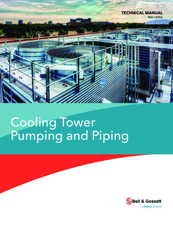
TECHNICAL MANUALTEH-1209ACooling TowerPumping and Piping
TABLE OF CONTENTSSubjectPage1.0 Legend. 12.0 Tower Pumping. 2A. Open Tower System Pump Head Requirements. 2B. Downcomer Siphon draw. 23.0 Pump Curve Maintenance. 5A. Tower Bypass into pump suction line. 5B. Pan drain-down startup. 6C. Tower Vortexing. 74.0 NPSH; Cavitation. 75.0 The Tower Pump and it’s Suction Line. 12A. Leave the Suction line alone. 12B. Place the pump below the pan water level. 12C. Avoid “ABOVE THE PUMP” air traps in the suction line!. 13D. Avoid Fine Mesh High Pressure Drop Strainers in Suction Line. 136.0 Predicting Pump Operating Points. 14A. The System Curve. 14B. Non Bypassed Tower Pump Operating Shift. 167.0 Tower ByPass. 17A. Tower Bypass General Methods. 17B. Bypass Valve Operational Characteristics; Valve Coefficient (Cv). 19C. Tower Bypass; Design for Flow Stability. 218.0 Cooling Tower Filtration. 24A. Side Stream Filtration. 24B. Full Stream Filtration. 25C. Basin Filtration. 25D. Filter Media. 26E. Backwash Considerations. 269.0 Cooling Tower Freeze Protection. 26A. Water Lines. 26B. Fill Media Protection. 26C. Heater Pump Selection. 2710.0 Free Cooling with Cooling Towers. 27A. Indirect Cooling. 27B. Direct Cooling. 2811.0 Wet-Well Sump(Vertical Turbine Pumps). 28A. Pump Selection. 2912.0 Multiple Loads. 29A. Independent Circuit Pumping. 29B. Header and Return System. 29C. Header and Return System with Flow control. 31D. Parallel Pumping. 31E. Staging Sequence. 3213.0 Head Pressure Control. 3214.0 Closed Circuit Cooling Towers. 33A. Pump Head. 34B. Freeze Control. 34C. Air Control. 3415.0 Pumping Practices. 34A. Discharge Piping Guidelines. 34B. Suction Piping Guidelines. 3416.0 Cooling Tower Makeup water. 3517.0 Cooling Tower Guidelines. 3518.0 Equalization Lines. 3619.0 Blowdown Arrangement. 37NOTE:Pump curves and other product data in this bulletin are for illustration only. See Bell & Gossett product literature for moredetailed, up to date information. Other training publications as well as the Bell & Gossett design tools described in thisbooklet including the System Syzer, analog and digital versions, and ESP Plus are all available from your local Bell & Gossettrepresentative. Visit www.bellgossett.com for more information or contact your Bell & Gossett representative.
1.0 LEGENDHEAT REJECTION EQUIPMENTTRIPLE-DUTY VALVEPUMPCONDEVAPPRESSURE REDUCING VALVECHILLERMIXING/DIVERTING VALVESTRAINERCOOLING TOWER–DRAINNODEPRESSURE GAUGESAUTOMATIC FILLNON-SLAM CHECK VALVEAIR SEPARATOR WITHEXPANSION TANKBALANCE VALVE (PLUG)CONDENSERHEAT REJECTION EQUIPMENTAUTOMATIC FLOWCONTROL VALVEVALVEAUTOMATIC VALVEBUTTERFLY VALVEAUTOMATIC BUTTERFLY VALVE1
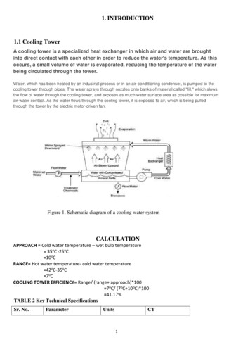
2.0 TOWER PUMPINGrequires pump work and open statics becomes an importantconsideration for pump selection.Tower pumping does not present great difficulty in termsof a good pump application. This is because of a normallyhigh order of application safety factor. Troubles do occuroccasionally, however, and these troubles can be classified ascaused by:1. Incorrect pump head estimation.2. Pump cavitation and loss of pumping ability, ascaused by inadequate pump suction pressure.3. Air in pump suction; as caused by tower pan vortex,pan drain down or faulty bypass.4. Unstable pump operational points as caused by:(a) Improper application of tower bypass controls.(b) High pressure drop tower spray nozzles incombination with tower bypass.5. Inadequate maintenance procedures causing:(a) Plugged suction strainer.(b) Lack of tower treatment with consequent foulingof the condenser.It is intended that each potential trouble source be evaluatedso that the necessary design safeguards can be erectedagainst operational problems.DWATER WILLREACH THIS LEVELw/o PUMP ENERGYHsWATER LEVELPUMP SUCTIONAHBSCPUMPFigure 2Open Piping CircuitIn Figure 2, the required pump head will be the pipe flowfriction loss from A to D plus the energy head (Hs) required toraise water from the lower to higher level.The cooling tower circuit differs slightly from the basic “open”circuit in that the discharge piping is connected directlyto a distribution basin. Some towers are furnished witha distribution manifold with nozzles which requireadditional pressure.DHrA. Open “Tower” System Pump HeadRequirementsEHsWater level pumpsuction sideDischargePipingHoThe pumping head determination procedure for the “open”tower piping loop differs from the conventional “closed” looppiping circuit used for most Hydronic (Heat-cool) applications.The difference concerns consideration of “open” loop staticheads.The closed loop circuit has no need for consideration of staticheads for pump selection because of a balance or cancellationof static heads between the supply and return risers. Statichead lost by water flow to any height in the supply pipingis cancelled by a static head “regain” as water flows downthe return piping. The only pump head requirement for the“closed” loop is that due to flow-friction pressure drop; staticheights are not considered.ACondenserWater will reachthis level withoutH pump work, “H”cancelsBCFigure 3Typical “Open” Tower PipingFor the tower piping circuit, the pump must overcome thepiping flow friction loss; piping, condenser, cooling towerlosses, and valves. It must also provide the energy headnecessary to raise water from a low to a higher statichead level.Most discussions concerning tower and/or open pipingcircuits would simply define the required pump static energyhead as Ho (in Figure 3); the “open” height of the pipingcircuit. This is, however, an ever-simplified assumption whichmay or may not be true depending on whether or not a“siphon draw” is established in the downcomer returnpiping DE.The nature of the downcomer siphon draw and its limitationsshould be evaluated.CLOSED LOOPPIPING CIRCUITFLOW-FRICTIONLOSS hB. Downcomer Siphon DrawPUMPIn Figure 3, water is being discharged at E. Pressure at D mustbe equal to exit loss plus flow-friction loss DE and minus thestatic pressure reduction caused by downcomer return staticheight Hr.Pressure reduction to D as caused by static height Hr willgenerally, but not always, permit cancellation of height Hr as apart of the required pump head. This is because of a resultantsiphon draw action in the downcomer.Figure 1Static Height (H) Not Considered for Pump Selectionin Closed LoopThe “open” or tower circuit is different from the “closed”loop circuit. The difference is that all static heads are notcancellable. In the open piping circuit, the pump mustraise fluid from a low reference level to a higher level; this2
High downcomer pressure drops can be caused by controlvalves or tower spray nozzles. When this pressure dropplus the downcomer pipe flow-friction loss exceedsfluid head Hr, the pump head must be increased bythe difference Dh(DE) minus Hr. Total pump head thenbecomes:Pump Head;Δh(DE) Hr Hs Δh(AD) [Δh(DE) – Hr]Given that the “siphon draw” does indeed occur, the requiredpump head will become:Pump Head (Figure 3) Ho Δh(AE)The pump head selection statement shown above iscommonly accepted as a truism. It has limitations, however,and will not apply under certain circumstances. Thesecircumstances should be understood if unnecessary cost andembarrassment are to be avoided by the consultant.Exit loss and flow-friction loss in the downcomer will generallybe less than the downcomer height Hr. For this circumstancethe downcomer must operate at sub-atmospheric pressurewhen the siphon draw is established. If the downcomervacuum is broken, the expected siphon draw will not occurand the estimated pump head may be inadequate.The expected downcomer return siphon draw vacuum can bebroken by any of three basic application circumstances: Top vented downcomer. Inadequate downcomer flow rates; bottom venteddowncomer. Fluid vapor pressure or flash considerations.(2) Bottom Vented Downcomer; Inadequate Flow RatesDowncomer flow rates can be so low, relative to pipesize, as to allow air to enter at the pipe discharge. Thiscircumstance will cause the downcomer to become ventedand will prevent formation of the necessary siphon drawvacuum.Tests conducted at Bell & Gossett indicate that the siphondraw will not be established when the actual flow-frictionloss rate is less than the order of 1'/100' based on cleanpipe pressure drop evaluation.Pump head requirements for the bottom venteddowncomer will be as previously noted for the topvented circumstance.An unfortunate operational sequence can occur duringpump start-up when the pump energy head is devotedtowards simply raising water from the low level pan to thehighest part of the system.During this start-up period, flow rates can be so low as tocause “bottom venting” and prevent (sometimes forever)formation of siphon draw circumstances and full designflow rates. A water legged discharge or discharge reducerwill provide automatic siphon draw establishment so longas minimal “start-up” flow velocity in the downcomer is tothe order of 1 ft./sec.(1) Top Vented DowncomerFigure 3A downcomer vent will break the siphon draw vacuum. Thevent may be a simple loose pipe connection - or it may bea mechanical vent purposefully applied at the downcomerreturn high point.Vents are sometimes applied to establish known referencepumping conditions when downcomer return siphondraw conditions propose stability problems; as with a veryhigh downcomer, when fluid boiling is a probability orwhen start-up downcomer flow rates are anticipated asinadequate for the siphon draw.Given a top vented downcomer, it will be seen that thepump must raise water from the pump suction pan waterlevel to the highest vented point in the downcomer.Considering this point to occur at D in Figure 3, therequired pump static head will become Ho Hr or Hs.The total pumping head to point D will become Hs plusthe flow-friction loss Δh(AD). Separate consideration mustnow be given to the downcomer return.Since the pump has raised water to level “D” it will haveprovided a fluid head equal to Hr to overcome flow-frictionloss in the downcomer. There are two different pumpingpossibilities; fluid head Hr greater than downcomer flowfriction loss Δh(DE) and the reverse: Hr less than Δh(DE).The usual pumping circumstance will be the conditionof Hr greater than Δh(DE). This is because the availablefluid head Hr is the equivalent of 100 ft./ 100 ft. pipefriction loss rate. Downcomer piping flow-friction losswill generally be to the order of 4 ft. /100 ft. Since thepump has already provided the necessary fluid head toflow the downcomer, Hr Δh(DE); friction flow loss in thedowncomer is not a part of the required pump head andtotal pump head becomes:Pump Head; Hr * Δh(DE) Hs Δh(AD)OVERSIZEDDOWNCOMERS(MIN. VELOCITY 1 FT./SEC.)WATERLEGREDUCERONE PIPE SIZEOR VALVESPLASHPANSPLASHPANFigure 4Water Leg or Reducer Help Establish Siphon Draw inDowncomer on Start-UpIn Figure 4, air entry into the pipe discharge is prevented.The minimum flow velocity pulls air bubbles down thepiping, finally evacuating the downcomer of air andestablishing the siphon draw condition; downcomer pipefull of water and operating at sub-atmospheric pressure.Unusual application circumstances will sometimesestablish such a low start-up flow rate (less than 1 ft/sec. velocity) that air bubbles are not carried down thepiping. The downcomer cannot then be emptied of air andexpected siphon draw will never occur.3
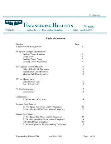
For this circumstance it is necessary to separately fill thedowncomer with water. This can be accomplished byvalve closure at the piping exit in combination with a topvent. During start-up, the exit valve is closed and the ventopened. After the piping is filled, the vent is closed arid theexit valve opened.Figure 6 illustrates an example tower schematic for aninstallation located at 6,000 ft. elevation. The tower is to beused to dissipate heat from 180º water; what is requiredpump head? Figures shown correspond to available fluid head over andabove vapor pressure for the water temperature shown.DVentHr 30'Hs 40'h(DE) 2'EEh(AE) 30'AB(4) Example ProblemReference to Table 1 shows that the cancelable siphondraw height for 6,000 ft. elevation and 180º water is only10', while downcomer return static height is 30 ft.If conventional pump selection practice were to befollowed, the pump selection would be:Wrong Pump Head Δh(AE) Ho 30' 10' 40 ft.(3 ) Siphon Draw Limitation Due to Vapor Pressure; FluidBoilingGiven sufficiently low sub-atmospheric pressure, anyfluid will flash or boil. Fluid pressure in the downcomerpiping cannot be less than the pressure at which the fluidboils. Fluid vapor pressure thus provides a siphon drawlimitation.Theoretical cancellable downcomer return static height(due to sub-atmospheric siphon draw) will vary dependenton fluid vapor or boiling pressure and on atmosphericpressure as this changes from sea level. The variation forwater as effected by water temperature and height abovesea level is shown in Table 1.It will be noted that this pump selection provides a perfectexample of low start-up flow rates; the pump head willjust be enough to raise water to the system top. Start-upflow rate will be insignificant.Even given the special application precautions previouslystated, however, the pump selection would not work Thisis because water flash in the downcomer will preventestablishment of the presumed 30’ siphon draw head. Inthis instance water would flash because the downcomerreturn static height exceeds the cancellable siphon drawhead (see Table 1; 6,000 ft. at 180º 10').When downcomer return height exceeds cancellablesiphon draw head, it is necessary to separately evaluatedowncomer needs. For these circumstances:The summation of cancellable siphon draw static heightplus downcomer return flow friction loss must exceeddowncomer return height; the excess providing anti-flashpressurization.The necessary downcomer flow-friction loss wouldgenerally be established by a balance valve positionedclose to the outlet (E). This valve will now provide thenecessary “back pressure” to maintain downcomer fluidpressure at above its boiling or vaporization point.For the particular example, a valve pressure drop equal tothe order of 23 ft. would establish an overall downcomerreturn flow-friction loss of 25 ft. (23 2 25 ft.).Table 1Water Temperature 5.814.613.512.211.110.08.87.66.45.2CFigure 6Example ProblemFigure 5Exit Valve & Vent Permit “Start-Up” Fill ofDowncomer 22.2h(AD) 23'Ho r ��–TABLE 1* MAXIMUM THEORETICAL DOWNCOMERRETURN CANCELLABLE STATIC HEIGHT BECAUSE OFSIPHON DRAW—WATER ONLY4
A. Tower Bypass into pump suction lineA 25' downcomer flow-friction loss added to thetheoretical cancellable height of 10 ft. will establish apressure over and above boiling of 5 ft. at “D”.25' 1 0' 35';5' over static height Hr 30'The correct pump head selection now becomes:Pump Head Δh(AD) Δh(DE) Δh(Valve) Ho 28' 2' 23' 10' 63 ft.For this particular example, a simpler solution could applyan open vent at “D”; eliminating need for the downcomerbalance valve and its setting*. Required pump head wouldthen become:Pump Head Δh(AD) Ho Hr 28' 10' 30' 68 ft.Either correct solution will provide required design flowrates. Design flow rates would not and could not beestablished by the “conventional” head selection of 40 ft.* In this case, the pump provides an “available” head at Dof 30'. This fluid head is available for downcomer flow andis greater than flow-friction loss in the downcomer (Δh DE)of 2 ft. Downcomer return flow friction loss can then beneglected since downcomer fluid will be in “free fall”.Improperly applied tower bypass lines connected directlyto the pump suction line can cause introduction of largeamounts of air into the pump. Air can be drawn into the pumpsuction when sub-atmospheric pressures exist at the bypassand discharge line connections.AirWater LegAir introduced because subatmospheric pressureWaterCCondenserHLLockouttower fansbeforebypassControl ValveH2AAir & WaterBalance ValveH1BSuctionFigure 7Tower Bypass Can Introduce Air Into Pump Suction onFull Bypass – Not RecommendedWhen the tower illustrated in Figure 7 is in full bypass,pressure at “B” will be above atmospheric pressure by anamount stated by static height H1. Pressure at “C” can becomesub-atmospheric, causing air suction unless static pressurereduction caused by height H2 is counter-balanced by anequal to or greater flow-friction loss in the bypass line.The bypass control valve and bypass piping should bedesigned for sufficient pressure drop to prevent subatmospheric pressure at “C” and to cause water to raise intothe water leg when the tower is in bypass.The desired result will generally be obtained by use of abypass balance valve with the valve so set that at full towerbypass (Figure 8), bypass “back pressure” causes water toraise into the water leg to some set point as established by apet cock design observation point.3.0 PUMP CURVE MAINTENANCEIn order for a pump to fulfill its fluid flow function, it must beprovided with a solid stream of fluid. The Centrifugal Pumpcannot pump fluid and vapor or fluid and air and still provideflow in accordance with its published curve.a. The pump suction must be under enough pressure sothat vapor flash pressure within the pump (cavitation) isprevented.b. The pump cannot be expected to provide design flowwhen large quantities of air are drawn into the pumpsuction; as by tower pan vortex, pan draw-down orbypass vacuum.In addition to flow capacity reduction, the pump will oftenbe mechanically damaged by “shock” loads applied to theimpeller or its shaft because of cavitation or air in the suctionline.Large quantities of air in the suction line will break pumpshafts in remarkably short order. This is because the pumpimpeller alternates between virtual no load when an air “gob”enters the impeller casing and an instantaneous shock loadof very high order when it slugs against suddenly introducedwater.There are three basic ways for air to be drawn into the suctionpiping:Tower bypass into pump suction line.Pan drain-down on start-up.Tower vortexing.Petcockobservation pointsNo air suction pressuregreater than atmosphericLockouttower fansbeforebypassAH1CondenserH2Control ValveBalance ValveFigure 8Properly Set Balance Valve Prevents Air Suction intoPump – Not RecommendedIt should be noted that Tower bypass directly into the towerpan eliminates any possibility of air suction into the pumpbecause of bypass operation and is generally preferred.Cooling tower minimum flows (turn-down) make this systemvery difficult to flow balance. If the system is out of balance, itwill draw air into pump or loss heat transfer in the condenser.5
In Figure 10, the pump must fill the condenser, and allreturn piping each time it starts. In addition to a non-floodedcondenser on start-up, the pipe and condenser waterfill requirement will almost assure pan drain-down andconsequent suction line air problems.Normally a system is balanced at full flow conditions. Atminimum flow the conditions and pressures are different thanbalance point. The control valve will modulate continuallyat partial loads trying to maintain the cooling water supplytemperature. It must be kept in mind that the cooling towerfill also has minimum flow requirements. As a rule of thumb,most manufacturers require a minimum flow of 25% ofdesign in the summer to prevent chemical contaminationof the fill and 50% of design flow in the winter to preventfreezeup. The designer should specify the cooling towerwith weirs or dams in the hot water basin. These devices willallow reducing flows to properly distribute through the fill,otherwise the minimum flows can damage the tower.Example:Tower gpm: 3000Flow allowed to bypass in the summer: (1-.25) * 3000 2250 gpmFlow allowed to bypass in the winter: (1-.50) * 3000 1500 gpmLockouttower fansbeforebypassControl ed onpump startCondenserPRV set at less thanstatic pressureFillSFigure 11Check, Water Leg & Fill Prevent Piping to TowerDrainage – RightIn Figure 11, the check valve prevents back drainage of thevertical tower piping, while the water leg prevents drainage ofthe inside horizontal return piping.As a general rule, tower piping systems should be fitted witha piping fill line located at the check valve discharge. The fillline will provide two functions.1. It permits filling of the condenser piping independentof the tower pan and pump. The hazards of pan draindown on initial pump start-up can be avoided.2. It is important on chiller start-up that the condenserbe flooded on the tower side. Many condensers arelocated above the tower pan water level and additionalinsurance as to a flooded condenser under theseconditions can be provided by use of an automatic fillor Pressure Reducing Valve. This valve would be set tomaintain fill to just below the topmost piping point.Use of the Pressure Reducing Valve also guards against backdrainage problems as caused by a leaking check valve.CondenserBalance ValveFigure 9Bypass to Tower Preferred Bypass SystemFigure 9 illustrates a way of by-passing into the tower pan.B. Pan Drain-Down on Start-UpMany tower pans do not contain sufficient water volume to fillthe condenser piping. On pump start-up, the pump can drainthe pan dry or lower pan water level to the point of startinga vortex. In either event, air will be drawn into the pumpsuction; usually with disastrous results.Right and wrong applications are shown concerning the pandrain-down problem.PRESSUREREDUCING VALVETRIPLE-DUTYVALVEFILLCondenserFigure 11ALocation of Fill Valve with a Multi-Purpose Valve –Reference Figure 11No Check ValveIn Figure 11, it will be noted that the bleed blow-down islocated in the top horizontal return piping run. Bleed will onlyoccur during pump operation. The top or “outside” horizontalreturn piping will always drain to the tower and location ofbleed blow-down in this line is to be recommended.Figure 10Tower Piping and Condenser Drains into andOverflows Pan on Pump Shut-Down – Wrong6
Design application points concerning stable pump operationwill be evaluated after consideration of the suction linepressure drop or cavitation problem.C. Tower Vortexing; Excessive Exit Velocities4.0 NPSH; CAVITATIONIt is well known that fluids boil at defined tempera
Cooling Tower Pumping and Piping - Xylem . Pump