Transcription
Note: This is a reference cited in AP 42, Compilation of Air Pollutant Emission Factors, Volume I StationaryPoint and Area Sources. AP42 is located on the EPA web site at www.epa.gov/ttn/chief/ap42/The file name refers to the reference number, the AP42 chapter and section. The file name"ref02 c01s02.pdf" would mean the reference is from AP42 chapter 1 section 2. The reference may befrom a previous version of the section and no longer cited. The primary source should always be checked.AP42 Section:113.4IBackground Chapter 14Reference:l8Title:Cooling Tower Drift Test Report forUnnamed Client of the CoolingTower Institute, Houston, Texas.Midwest Research Institute (1989).
II\\SUMMARV\The testing services of Midwest Research Institute (MRI) wereretained byito conduct a drift test on a\ 4-cell,I Themechanical-draft, cross-flow cooling tower located atwork was performed by MRI as an independent test contractor.Cooling tower drift is defined as the percent of water flow throughthe tower which exits through the fan in the form of water droplets andaerosols. The amount of drift from the tower was determined by isokineticallysampling a representative fraction o f the tower airflow and measuring theamount of droplets and aerosol leaving the stack. Inductively coupled argonplasma spectroscopy (ICP), an extremely sensitive detection technique, wasthen used to measure the concentration of three selected trace constituents(Na, Ca, Mg,) in the basin water and water collected from the airflow exitingthe fan stack. From the measurements of the selected trace constituents inthe isokinetic sampling train and the same trace constituents in the basinwater, the drift rate was calculated.The calculated drift rates were between 0.0522% and 0.0543% forstack No. 2, depending on which of the three tracers was used. Whenresults are averaged for all tracers, a drift rate of 0.0535% is obtainedfan stack No. 2.The average drift rate from fan stack No. 2representative of the drift rate of the tower.1fantheforwas
COOLING TOWER TEST REPORT',IDRIFT TESTON THE4-CELL, MECHANICAL-DRAFT, CROSS-FLOWCOOLING TOWERI.INTRODUCTIONThe testing services of Midwest Research Institute (MRI) wereretained byto conduct a drift test using modifiedmechanical-draft,EPA Method 5 isokinetic sampling techniques oncross-flow cooling tower. The cooling tower is located at\The work was performed by Mr. Nicholas M. Stich and Mr. George Cobb of MRI.The tower manufacturer was represented byI was represented by Mr.1The thermal and drift tests were oriqinally scheduled for the weekIOf11.TEST SITE DESCRIPTIONis located atin\cooling tower provides cooling water to steamcondensers. The cooling tower is located in an unobstructed area on the northside of the plant.I.The cooling tower consists of four mechanical-draft, cross-flowcells in a continuous straight line with a common cold water basin beneath the128-ft diameter fan driven by atower. Each cell is equipped with a100-hp motor. The hub seal is 96 in. in diameter. The fan stack is 324 in.in diameter at the sample plane location and constructed of fiberglass.An underground steel conduit returns hot water from the plant to thecooling tower. The main line then tees off to feed two individual 30-indiameter cell risers. Pitot taps for water flow measurement were locate inthe 30-in lines.2
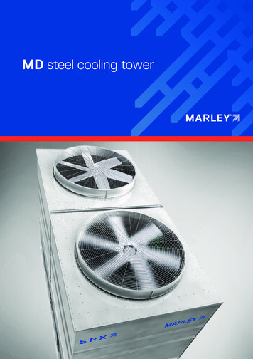
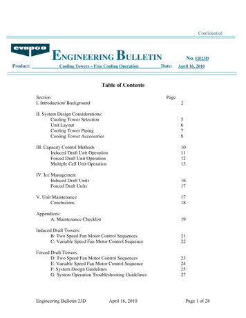
The cold water from the cooling tower basin is collected in the pumpforebay adjacent to the tower where two pumps are used to return cold water tothe plant. Taps with temporary standpipes were used for the collection ofbasin water samples.111.SAMPLING SEQUENCEThe test sequence for the drift test was as -follows:1.Water flow and fan horsepower measurement were conducted and the toweroperations were monitored.2.Drift sample and airflow measurement locations were calculated.3.A basin water sample was collected.4.Isokinetic drift sampling of the selected fan stack was conducted.5.Isokinetic drift sampling of the fan was completed.6.A second basin sample was collected at the conclusion of the test. Thetwo basin samples were composited into one basin water sample.7.The drift samples were recovered from the sample collection system.8.The basin composite, water blank, and drift impinger samples were acidstabilized and transported to the laboratory for analysis.IV.DRIFT TEST EQUIPMENTThe drift sampling system used for the test is shown schematicallyin Figure 1. The key components are described below.AIR PITOT/DRIFT PROBE:Since cyclonic flow can bias the drift results, adjustments in thesampling technique must be used to eliminate this bias. A special MRI airpitot/drift probe assembly was developed t o allow unbiased sampling. If thesample nozzle is not aligned with the flow, then the effective velocitythrough the nozzle opening is reduced by the cosine of the angle between theflow and and stack axis.This results in a sample which is not trulyisokinetic and thus the alignment approach1 must be used for the drift test to1Peeler, J.W., F.J. Phoenix, and D.J. Grove, "Characterization of CyclonicFlow and Analysis of Particulate Sampling Approaches at Asphalt Plant,"Entropy Environmentalists, Inc.3.
eliminate this bias. Since the sample proportionality could be compromisedwith the alignment approach, proportional sampling needs must be satisfied byadjusting the nominal base sample time by the cosine of the cyclonic flowangle.Airflow, fan discharge temperature, and the angle of cyclonic flowwere measured with this probe assembly. The air pitot/drift probe assemblywas equipped with:1.S-type primary pitot tips which are connected to a manometer tomeasure air velocity.2.Secondary pitot tips which are positioned at 90 degrees from theprimary pitot tips. The secondary set of pitot tips are connectedto a separate manometer to align the probe and compensate for anycyclonic flow effects.3.A temperature sensor connected to a digital readout to measure thestack temperature.4.A protractor attached to the probe assembly to determine the anglethat the probe was rotated during the cyclonic flow determination.5.A stainless steel drift sample nozzle and flexible Teflon sampleprobe which are connected to the drift collection train.SAMPLE LOCATIONS:Since drift is defined as the amount of droplets or aerosols exitingthe fan stack, the drift tests must be made at the top of the fan stack.Also, the proximity of the sample locations to the fan required that thestation locations be adjusted for the hub effect. Sample locations weredetermined using the equation for equal annular areas for fan discharge fromChapter 5 of the CTI Manual.DRIFT COLLECTION TRAIN:The drift collection train consisted of four high capacity impingersand a filter assembly. Impingers 1 and 2 contained distilled water and wereused to scrub out the aerosols and water droplets. The third impinger wasused to collect any water droplets that might be carried over from theprevious impingers. The filter was used as the final collection medium andwas placed between impinger 3 which was dry and impinger 4 which containedsilica gel. The sampling train was kept iced during testing t o help reducethe water vapor pressure and to further improve collection efficiency.4
CONTROL CONSOLE AND PUMP:The control console and pump used was a High Volume Sampling System(HVSS) consistent with EPA Method 5 requirements. The impinger train wasconnected to the console via a sample line through the leak free vacuum pumpcapable of up to 4 cfm. The modular vacuum pump has two control valves toadjust and maintain the desired sampling rate. The console contained acalibrated dry gas meter, digital temperature readout, manometers, andassociated controls.V.DRIFT TEST METHODSThe tower’s circulatingTesting was conducted onwater flow was 103.1% of design and the fan horsepower was 90.7% of design.The test data were acquired in accordance with applicable portions of the CTIATC-105 (1982) test code. The individual parameters were measured as follows:*Total circulating water flow was measured with two 20-point pitottraverses of the hot water return riser to the tower. A 42-inSimplex/Leopold-type pitot tube was used to measure the velocity ateach point. An air-over-water manometer was used for measuring thedifferential pressure between the impact and reference orifices ofthe pitot tube.*Fan motor power was measured with a clamp-on digital kilowatt meter,using the two watt meter method.*Air velocity was measured with four 10-point radial traverses of the .fan stack using the predetermined sampling locations. At each pointthe MRI air pitot/drift probe assembly was rotated until thepressure difference across the secondary pitot tips was zero. Whenthis zero differential had been obtained, the primary probe had beenaligned with the flow and the protractor was read to determine thecyclonic flow angle. The probe assembly was then used to measurethe velocity pressure and temperature at the sample point.The previously determined velocity pressure, stack temperature, andcyclonic flow angle were used by a Epson HX-20 computer to calculatethe required sample volume, isokinetic rate, and the adjusted basesample ti me.Sampling at each traverse location was commenced after the propersample rate was determined by turning on the sample pump andsimultaneously activating the variable timer function of the HX-20computer. When each sample time had ended, the pump was shut off,the air pitot/probe assembly was relocated to the next samplelocation, and the above procedure repeated until all 40 points hadbeen sampled.5
.: . .**The drift sample recovery was initiated by using distilled deionizedwater to rinse the stainless steel nozzle and flexible Teflon probeinto the contents of the first impinger. The impinger train wassealed and then removed from the cooling tower to the samplerecovery location where the remainder of the sample recovery wasperformed. The impinger volumes and rinse volumes were measuredand recorded. The impinger contents along with all rinses weretransferred to sample bottles. A distilled deionized water blankwas taken, Both the drift impinger samples and water blank werenitric acid stabilized and then returned to MRI for furtheranalysis.Basin water samples were taken at the beginning and at theconclusion of the drift test. The basin water sample was taken froma thermal well that was installed on the discharge side of thecirculating water flow pump. The samples were collected after thethermal well line was purged. The two samples were collected andthen combined into one composite basin water sample. The compositebasin sample was stabilized with nitric in the same manner as werethe impinger and water blank samples. The composite basin watersample was returned to MRI for further analysis.VI.SAMPLE ANALYSISThe samples were returned to MRI where they were logged into alaboratory notebook. Method 3050 was used to prepare the drift and basinwater samples for the analysis using Method 6010 as described below.METHOD 3050:Method 3050 i s an acid digestion procedure used to preparesediments, sludges, and soil samples for analysis by flame or furnace atomicabsorption spectroscopy (FLAA and GFAA, respectively) or by inductivelycoupled argon plasma spectroscopy (ICP).A representative sample is digested in nitric acid and hydrogenperoxide.The digestate is then refluxed with either nitric acid orhydrochloric acid. Dilute hydrochloric acid is used as the final reflux acidfor (1) the ICP analysis of As and Se, and (2) the flame AA or ICP analysis ofAl, Ba, Ca, Cd, Cr, Co, Cu, Fe, Mo, Pb, Ni, K, Na, T1, V, and Zn. Dilutenitric acid is employed as the final dilution acid for the furnace AA analysisof As, Be, Cd, Cr, Co, Pb, Mo, Se, T1, and V. A separate sample is dried fora total solids determination.METHOD 6010:Method 6010 describes the procedures for inductively coupled argonplasma spectroscopy (ICP) in determining elements including metals insolution. This method is applicable to a large number of metals and wastes.All matrices, including groundwater, aqueous samples, EP extracts, industrial6
wastes, soils, sludges, sediments, and other solid wastes, require digestionprior to analysis.The simultaneous, or sequential, multielemental determination ofelements by ICP is measured by element-emitted light by opticalspectrometry. Samples are nebulized and the resulting emission spectra areproduced by a radio-frequency inductively coupled plasma. The spectra aredispersed by a grating spectrometer, and the intensities of the lines aremonitored by photomultiplier tubes. Background correction is required fortrace element determination.VII.RESULTS AND CONCLUSIONSThe following equation is used by the MRI drift computer program tocalculate the drift results:% Drift NFA NWT NZAWFREQTBTC100 * ( NFA* NWT)/ ( NZA* WFR * EQT * BTC)Net Fan Area (square feet)Net Weight of Tracer (vg)Nozzle Area (square feet)Water flow Rate (grams per minute) Equivalent Sample Time (240 minutes) Basin Tracer Concentration (vg/g)The table below summarizes the results of the laboratory analysisand drift UBASINCONC.u% 522The results of the drift test conducted forindicate that fan stack No. 2 had an average drift rate of 0.0535%. The driftrate of the the fan tested should be representative of the average drift rateof the tower.7-
L-l-----------1IIIIIIIIIIIIIIJaWL2D.-U.
."APPENDIX ASUMMARY OF RESULTSDRIFT TESTON THE4-CELL,MECHANICAL-DRAFT, CROSS-FLOWCOOLING TOWERA- 1
.FILE NAMERUN #LOCATIONDATEPROJECT #: 22:43:14PROGRAM,,- v2.1:: FAN # 2::INITIAL METER VOLUME (CUBIC FEET) FINAL METER VOLUME (CUBIC FEET) METER FACTOR FINAL LEAK RATE (CU FT/MIN) 735.0001075.8200.98570.000335.946302.708NET METER VOLUME (CUBIC FEET) GAS VOLUME (DRY STANDARD CUBIC FEET) BAROMETRIC PRESSURE (IN. HG) STATIC PRESSURE (INCHES H20) 28.05-0.17PERCENT OXYGEN PERCENT CARBON DIOXIDE MOISTURE COLLECTED (ML) PERCENT WATER **SATURATED STACK**21.00.00.03.6DRY MOLECULAR WEIGHT WET! MOLECULAR WEIGHT 28.8428.45AVERAGE METER TEMPERATURE (F.) AVERAGE DELTA H (IN. H20) AVG.SUM O f SQR DELTA P (for 8 ISOKINETIC) 91.61.690.50348 ISOKINETIC 102.7AVERAGE STACK TEMPERATURE (F.) AVG. SUM of SQR DELTA P * COS of ANGLE (IN. H20) PITOT COEFFICIENT SAMPLING TIME (MINUTES) NOZZLE DIAMETER (INCHES) 79.50.38160.84176.10.4413STACK AXIS (INCHES) HUB AXIS (INCHES) NET FREE STACK AREA (SQUARE FEET) 324.096.0522.29STACK VELOCITY (ACTUAL, FEET/MIN) FLOW RATE (ACTUAL, CUBIC FT/MIN) FLOW RATE (STANDARD, WET, CUBIC FT/MIN) FLOW RATE (STANDARD, DRY, CUBIC FT/MIN) 1,352706,171647,664624,225- - - - - - - DRIFTANALYSIS ----TRACERANALYZEDSAMPLEWEIGHT( mcg )NAMGCA735010405040WATERBLANKBAS INCONC .(mcg/g )(mcg/g007401045240AVERAGE PERCENT DRIFT OF ALL TRACERS ANALYZED0.05400.05430.05220.0535A-2i
.FILE NAMERUN #LOCATIONDATEPROJECT #:: FAN # 2:1 lv2.1I:* *METRIC UNITS* *INITIAL METER VOLUME (CUBIC METERS) FINAL METER VOLUME (CUBIC METERS) METER FACTOR FINAL LEAK RATE (CU M/MIN) NET METER VOLUME (CUBIC METERS) GAS VOLUME (DRY STANDARD CUBIC METERS) 20.81230.4630.98570.00009.5138.571712-4BAROMETRIC PRESSURE (MM HG) STATIC PRESSURE (MM H20) 21.00.00.03.6PERCENT OXYGEN PERCENT CARBON DIOXIDE MOISTURE COLLECTED (ML) PERCENT WATER 28;8428.45DRY MOLECULAR WEIGHT WET MOLECULAR WEIGHT AVERAGE METER TEMPERATURE (C.) AVERAGE DELTA H (MM H20) AVG. SUM of SQR DELTA P (for % ISOKINETIC) %16:39:52PROGRAM33.142.92.54102.7ISOKINETIC AVERAGE STACK TEMPERATURE ( C . ) AVG. SUM of SQR DELTA P * COS of ANGLE (MM H 2 0 ) PITOT COEFFICIENT SAMPLING TIME (MINUTES) NOZZLE DIAMETER (MM) 26.41.920.84176.111.21STACK AXIS # 1 (METERS) STACK AXIS # 2 (METERS) CIRCULAR STACKSTACK AREA (SQUARE METERS) 8.2302.43848.522STACK VELOCITY (ACTUAL, M/MIN) FLOW RATE (ACTUAL, CUBIC M/MIN) FLOW RATE (STANDARD, WET, CUBIC M/MIN) FLOW RATE (STANDARD, DRY, CUBIC M/MIN) 41219,99718,34017,676A-3 .
FILE NAMERUN #LOCATIONDATEPROJECT #./.POINT #:: FAN # 2:I:DELTA PDELTA H(IN. H20) (IN. H20)STACK TMETER T.IIF.)IN(F.) 433431.000'A-4. .( 16:41:39PROGRAMv2.155
APPENDIX 8F I E L D DATA SHEETSD R I F T TESTON THE4-CELL,MECHANICAL-DRAFT, CROSS-FLOWCOOLING TOWERE-1.
Ip p8-2
. .:.'.-.I:i8-3- . . . . .
:. .-. . . .
i.-MIDWEST RESEARCH INSTITUTEDrift Sample Recovery.File- . -Date1st ImpingerProbe RinseFinal Volume(includes rinses)YO b2nd Impinger3rd Impinger2229860Rinse Volume/QOInitial Volume62Net Volume6-5I32
.r',FILE NO.:r!-.,MIDWEST RESEARCH INSTITU Ei- 1DATA SHEET "C"UNITM E I S OF'T I M E : ST*RTVOLTSTEST DATE:UNlTM E A S OFENDAMPSPFr wIi'ITEST AVERAGE:MEAS. OF:UNIT- - - ------- --INSTRUMENT IDENTIFICATION8-6.-. . . . . .-i. .
.i.*.- MIDWEST RESEARCH INSTITUTEFILE NO.:WATERDATA SHEET "E"FLOW MEASUREMENTTEST DATE.1. .4II' C A L C U L A T E D V A L U E D E C R E A S E D B Y D I S T A N C E FROIA E N 0 OF P l T O T T U B E T O C E N T E R L I N E O F IMP/LCT "OLE-I8-7
.APPENDIX CLABORATORY A N A L Y S I SDRIFT TESTON THE4-CELL,MECHANICAL-DRAFT, CROSS-FLOWCOOLING TOWER .
:.:.,. . . . . . . . .: . . . . . . . . . . . . . . . . . . . . . . :. . . . . . . . . . . . . . . . .: . . . . . . . . . . . . . . . . . . . . . . :. . . . . . . . . . . . . . . . . . . . . . . . . . . . .c-2I
i N T E R U F I C ECCII'ltllJi\l ICAITI O NMIDWEST RESEARCH INSTITUTETo:From:D.Cobi.E.untMrClefidonc-3.I
Tsr.Lp NQ.:.12.7.4Des5clei.LnnSummary o f S a m p l e i ; n . s l y s i s tiesu1i:sSample Weighing D a t aI C M S a m p l e R a w and Calculated Ds,ti?.I n s t r u m e n t a l C h e c k S t a n d a r d , Dupl ica.te a n d3 p i [.::eData.I-Table1 c o n t a i n s t h e analyticai r e s u i t s oftheanalysis.T a . b i e 2 c o n t a i n s t h e s a m p l e w e i g h i n g d;tagenei-a.teddcringt!iedigestionof t h e s a m p l e s .T a b l e I: c o n t a i n s t h e I C A F s a m p l e rawdata a l o n g w i t h t h e blan!.: c o r r e c t e d c a l c r l a t e d s a m p l e d a t a a n d'table .4 inz.fr-L!mental ch-.ci:: standa;.dda.ta,t h e resul t i n g p e r c e n ti n c t r u m e n t a l d r i f t ani? d u p l ics.te d e t e r m i n a t . i n n a n d sili ke r e c o v e r yda.ts." r k c e l l o r m u l a s !.!sed i n t h e s e tables are i n c l u d e d forc ?in 1e t en es E.c-4I.
D e-s c r ie t j . !ICP-AES D a t a R e o o r t i n o8SheetControl Table E i i t o r n u t p u tDEC Command F i l e s UsedI C A F Sample Ha.w Data.Sample W e i g h i n g S h e e t - I n i t i a l W e i g h t sSample W e i g h i n g S h e e t - F i n a l W e i g h t sFhotocopy of M R I La.horatory GeneratedSamp 1e I n v e n t o r yP h o t o c o p i e s of N o t e b o o k ! Z 5 7 : 98-1!:K!W i t h t h e e x c e p t i o n o f p a r t number8,t h e photocopiesoft h e notebunl:: 1357:9R-1(:!0,t h i s f i l e con",insthe o n l y r e c o r dofthea.n.3iysis.T h i s f i l e shcr:ld t h e r e f o r ebea.rchivedas: - e q u i r e d b y t h e p r o j e c t o r aE. r e q i i i r e d b y M R I p o l i c y .Thisdata. h a c cuidergnne o n e l e v e l of s e n i o r - r e v i e wwithin he A n a l y t i c a i C h e m i s t r y Section.The NiiI & t a l i y Assura,nce U n i thas n o t reviewer: t h i s data.John S t a n l e y , H e x ii ? n a l y t i c a l Chemistry Section
\cooling tower provides cooling water to steam condensers. The cooling tower is located in an unobstructed area on the north side of the plant. The cooling tower consists of four mechanical-draft, cross-flow cells in a continuous straight line with a common cold water basin beneath the tower. Each cell is equipped with . a . 128-ft diameter fan .