Transcription
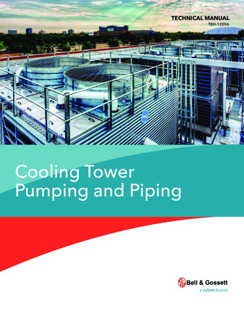
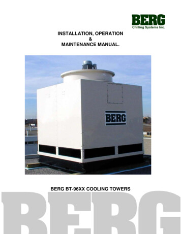
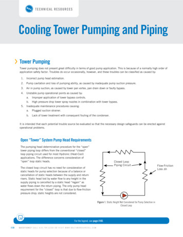
TECHNICAL RESOURCESCooling Tower Pumping and Piping››Tower PumpingTower pumping does not present great difficulty in terms of good pump application. This is because of a normally high order ofapplication safety factor. Troubles do occur occasionally, however, and these troubles can be classified as caused by:1.Incorrect pump head estimation.2.Pump cavitation and loss of pumping ability, as caused by inadequate pump suction pressure.3.Air in pump suction; as caused by tower pan vortex, pan drain down or faulty bypass.4.Unstable pump operational points as caused by:5.a.Improper application of tower bypass controls.b.High pressure drop tower spray nozzles in combination with tower bypass.Inadequate maintenance procedures causing:a.Plugged suction strainer.b.Lack of tower treatment with consequent fouling of the condenser.It is intended that each potential trouble source be evaluated so that the necessary design safeguards can be erected againstoperational problems.Open “Tower” System Pump Head RequirementsThe pumping head determination procedure for the “open”tower piping loop differs from the conventional “closed”loop piping circuit used for most Hydronic (Heat-Cool)applications. The difference concerns consideration of“open” loop static heads.Closed LoopPiping CircuitThe closed loop circuit has no need for consideration ofstatic heads for pump selection because of a balance orcancellation of static heads between the supply and returnrisers. Static head lost by water flow to any height in thesupply piping is cancelled by a static head “regain” aswater flows down the return piping. The only pump headrequirement for the “closed” loop is that due to flow-frictionpressure drop; static heights are not considered.Figure 1. Static Height Not Considered for Pump Selection inClosed LoopFor the legend, see page J165.J120Q U E S T I O N S ? C A L L 4 1 0 . 7 9 9 . 6 2 0 0 O R V I S I T W W W. B A LT I M O R E A I R C O I L . C O MFlow-FrictionLoss h
The “open” or tower circuit is different from the “closed” loop circuit. The difference is that all static heads are not cancelable. Inthe open piping circuit, the pump must raise fluid from a low reference level to a higher level; this requires pump work, and openstatics becomes an important consideration for pump selection.In Figure 2, the required pump head will be the pipe flow-friction loss from A to D plus the energy head (Hs) required to raise waterfrom the lower to higher level.DHsWater LevelPump SuctionWater WillReach This LevelWithout Pump EnergyAsHBCFigure 2. Open Piping CircuitThe cooling tower circuit differs slightly from the basic “open” circuit in that the discharge piping is connected directly to adistribution basin. Some towers are furnished with a distribution manifold with nozzles which require additional pressure.For the tower piping circuit, the pump must overcome the piping flow friction loss; piping, condenser, cooling tower losses, andvalves. It must also provide the energy head necessary to raise water from a low to a higher static head level.Reprinted with permission from Xylem, Inc. Copyright 2013.PRODUCT & APPLICATION HANDBOOK VOLUME VJ121
TECHNICAL RESOURCESCooling Tower Pumping and PipingMost discussions concerning tower and/or open piping circuits would simply define the required pump static energy head as Ho(in Figure 3); the “open” height of the piping circuit. This is, however, an ever-simplified assumption which may or may not betrue depending on whether or not a “siphon draw” is established in the downcomer return piping DE.The nature of the downcomer siphon draw and its limitations should be evaluated.DHrEHsWater LevelPump Suction SideHoCondenserDicharge PipingAHBWater WillReach This LevelWithout Pump Work,“H” CancelsCFigure 3. Typical “Open” Tower Piping CircuitDowncomer Siphon DrawIn Figure 3, water is being discharged at E. Pressure at D must be equal to exit loss plus flow-friction loss DE and minus thestatic pressure reduction caused by downcomer return static height Hr.Pressure reduction to D as caused by static height Hr will generally, but not always, permit cancellation of height Hr as a part ofthe required pump head. This is because of a resultant siphon draw action in the downcomer.Given that the “siphon draw” does indeed occur, the required pump head will become:PUMP HEAD in Figure 3 H0 h (AE)The pump head selection statement shown above is commonly accepted as a truism. It has limitations, however, and will notapply under certain circumstances. These circumstances should be understood if unnecessary cost and embarrassment are tobe avoided by the consultant.Exit loss and flow-friction loss in the downcomer will generally be less than the downcomer height Hr. For this circumstance thedowncomer must operate at subatmospheric pressure when the siphon draw is established. If the downcomer vacuum is broken,the expected siphon draw will not occur and the estimated pump head may be inadequate.J122Q U E S T I O N S ? C A L L 4 1 0 . 7 9 9 . 6 2 0 0 O R V I S I T W W W. B A LT I M O R E A I R C O I L . C O M
The expected downcomer return siphon draw vacuum can be broken by any of three basic application circumstances: Top vented downcomer. Inadequate downcomer flow rates; bottom vented downcomer. Fluid vapor pressure or flash considerations.Top Vented DowncomerA downcomer vent will break the siphon draw vacuum. The vent may be a simple loose pipe connection - or it may be amechanical vent purposefully applied at the downcomer return high point.Vents are sometimes applied to establish known reference pumping conditions when downcomer return siphon draw conditionspropose stability problems; as with a very high downcomer, when fluid boiling is a probability or when start-up downcomer flowrates are anticipated as inadequate for the siphon draw.Given a top vented downcomer, it will be seen that the pump must raise water from the pump suction pan water level to thehighest vented point in the downcomer.Considering this point to occur at D in Figure 3, the required pump static head will become:Ho Hr or HsThe total pumping head to point D will become Hs plus the flow-friction loss h (AD). Separate consideration must now be givento the downcomer return.Since the pump has raised water to level “D,” it will have provided a fluid head equal to Hr to overcome flow-friction loss in thedowncomer. There are two different pumping possibilities; fluid head Hr greater than downcomer flow-friction loss h (DE) andthe reverse: Hr less than h (DE).The usual pumping circumstance will be the condition of Hr greater than h (DE). This is because the available fluid head Hris the equivalent of 100 ft / 100 ft pipe friction loss rate. Downcomer piping flow-friction loss will generally be to the order of4 ft /100 ft. Since the pump has already provided the necessary fluid head to flow the downcomer, Hr h (DE); friction flowloss in the downcomer is not a part of the required pump head and total pump head becomes:If: Hr h (DE)Then: PUMP HEAD Hs h (AD)High downcomer pressure drops can be caused by control valves or tower spray nozzles. When this pressure drop plus thedowncomer pipe flow-friction loss exceeds fluid head Hr, the pump head must be increased by the difference h (DE) minus Hr.Total pump head then becomes:If: h (DE) HrThen: PUMP HEAD Hs h (AD) [ h (DE) – Hr ]Reprinted with permission from Xylem, Inc. Copyright 2013.PRODUCT & APPLICATION HANDBOOK VOLUME VJ123
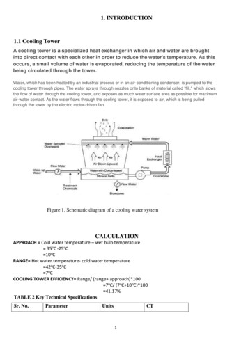
TECHNICAL RESOURCESCooling Tower Pumping and PipingBottom Vented Downcomer; Inadequate Flow RatesDowncomer flow rates can be so low, relative to pipe size, as to allow air to enter at the pipe discharge. This circumstance willcause the downcomer to become vented and will prevent formation of the necessary siphon draw vacuum.Tests conducted at Bell & Gossett indicate that the siphon draw will not be established when the actual flow-friction loss rate isless than the order of 1 ft /100 ft based on clean pipe pressure drop evaluation.Pump head requirements for the bottom vented downcomer will be as previously noted for the top vented circumstance.An unfortunate operational sequence can occur during pump start-up when the pump energy head is devoted towards simplyraising water from the low level pan to the highest part of the system.During this start-up period, flow rates can be so low as to cause “bottom venting” and prevent (sometimes forever) formationof siphon draw circumstances and full design flow rates. A water legged discharge or discharge reducer will provide automaticsiphon draw establishment so long as minimum “start-up” flow velocity in the downcomer is to the order of 1 ft/s.In Figure 4, air entry into the pipe discharge is prevented. The minimum flow velocity pulls air bubbles down the piping, finallyevacuating the downcomer of air and establishing the siphon draw condition; downcomer pipe full of water and operating atsubatmospheric pressure.Unusual application circumstances will sometimes establish such a low start-up flow rate (less than 1 ft/s velocity) that airbubbles are not carried down the piping. The downcomer cannot then be emptied of air and expected siphon draw will neveroccur.Oversized Downcomers(Minimum Velocity 1ft/s)Water LegSplash PanReducer One Pipe Sizeor ValveSplash PanFigure 4. Water Leg or Reducer Help Establish Siphon Draw in Downcomer on Start-UpJ124Q U E S T I O N S ? C A L L 4 1 0 . 7 9 9 . 6 2 0 0 O R V I S I T W W W. B A LT I M O R E A I R C O I L . C O M
VentDowncomerFor this circumstance it is necessary toseparately fill the downcomer with water.This can be accomplished by valve closureat the piping exit in combination with atop vent. During start-up, the exit valveis closed and the vent opened. After thepiping is filled, the vent is closed and theexit valve opened.CondenserFigure 5. Exit Valve and Vent Permit “Start-Up” Fill of Downcomer PipingSiphon Draw Limitation Due to Vapor Pressure; Fluid BoilingGiven sufficiently low subatmospheric pressure, any fluid will flash or boil. Fluid pressure in the downcomer piping cannot beless than the pressure at which the fluid boils. Fluid vapor pressure thus provides a siphon draw limitation.Theoretical cancelable downcomer return static height (due to subatmospheric siphon draw) will vary dependent on fluid vaporor boiling pressure and on atmospheric pressure as this changes from sea level. The variation for water as affected by watertemperature and height above sea level is shown in Table 1.Water Temperature (oF)Height Above Sea Level 2.219.918.615.911.75.2—Table 1: Maximum Theoretical Downcomer Return Cancelable StaticHeight (In Ft) Because of Siphon Draw - Water OnlyReprinted with permission from Xylem, Inc. Copyright 2013.PRODUCT & APPLICATION HANDBOOK VOLUME VJ125
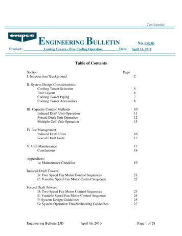
TECHNICAL RESOURCESCooling Tower Pumping and PipingDH r 30’ h(DE) 2’EHs 40’CondenserDowncomerReturnE h(AE) 30’ h(AD) 28’Ho 10’ABCFigure 6. Example ProblemExample ProblemFigure 6 illustrates an example tower schematic for an installation located at 6,000 ft elevation. The tower is to be used todissipate heat from 180 F water; what is required pump head? Figures shown correspond to available fluid head over and above vapor pressure for the water temperature shown.Reference to Table 1 shows that the cancelable siphon draw height for 6,000 ft elevation and 180 F water is only 10 ft, whiledowncomer return static height is 30 ft.If conventional pump selection practice were to be followed, the pump selection would be:WRONG PUMP HEAD h (AE) H0 30 ft 10 ft 40 ftIt will be noted that this pump selection provides a perfect example of low start-up flow rates; the pump head will just beenough to raise water to the system top. Start-up flow rate will be insignificant.Even given the special application precautions previously stated, however, the pump selection would not work. This is becausewater flash in the downcomer will prevent establishment of the presumed 30 ft siphon draw head. In this instance, water wouldflash because the downcomer return static height exceeds the cancelable siphon draw head (see Table 1; 6,000 ft at 180 F 10 ft).When downcomer return height exceeds cancelable siphon draw head, it is necessary to separately evaluate downcomer needs.For these circumstances:The summation of cancelable siphon draw static height plus downcomer return flow-friction loss must exceed downcomer returnheight; the excess providing anti-flash pressurization.The necessary downcomer flow-friction loss would generally be established by a balance valve positioned close to the outlet(E). This valve will now provide the necessary “back pressure” to maintain downcomer fluid pressure at above its boiling orvaporization point.J126Q U E S T I O N S ? C A L L 4 1 0 . 7 9 9 . 6 2 0 0 O R V I S I T W W W. B A LT I M O R E A I R C O I L . C O M
For the particular example, a valve pressure drop equal to the order of 23 ft would establish an overall downcomer return flowfriction loss of 25 ft (23 2 25ft).A 25 ft downcomer flow-friction loss added to the theoretical cancelable height of 10 ft (Table 1) will establish a pressure overand above boiling of 5 ft at “D.”25 ft 10 ft 35 ft; 5 ft over static height Hr 30 ftThe correct pump head selection now becomes:PUMP HEAD h (AD) h (DE) h (Valve) H0 28 ft 2 ft 23 ft 10 ft 63 ftFor this particular example, a simpler solution could apply an open vent at “D”, eliminating need for the downcomer balancevalve and its setting.* Required pump head would then become:PUMP HEAD h (AD) H0 Hr 28 ft 10 ft 30 ft 68 ftEither correct solution will provide required design flow rates. Design flow rates would not and could not be established by the“conventional” head selection of 40 ft.NOTE: In this case, the pump provides an “available” head at D of 30 ft. This fluid head is available for downcomer flow and is greater than flowfriction loss in the downcomer ( h DE) of 2 ft. Downcomer return flow-friction loss can then be neglected since downcomer fluid will be in “free fall.”››Pump Curve MaintenanceIn order for a pump to fulfill its fluid flow function, it must be provided with a solid stream of fluid. The centrifugal pump cannotpump fluid and vapor or fluid and air and still provide flow in accordance with its published curve.a.The pump suction must be under enough pressure so that vapor flash pressure within the pump (cavitation) isprevented.b.The pump cannot be expected to provide design flow when large quantities of air are drawn into the pump suction; asby tower pan vortex, pan draw-down, or bypass vacuum.Reprinted with permission from Xylem, Inc. Copyright 2013.PRODUCT & APPLICATION HANDBOOK VOLUME VJ127
TECHNICAL RESOURCESCooling Tower Pumping and PipingIn addition to flow capacity reduction, the pump will often be mechanically damaged by “shock” loads applied to the impeller orits shaft because of cavitation or air in the suction line.Large quantities of air in the suction line will break pump shafts in remarkably short order. This is because the pump impelleralternates between virtually no load when an air “gob” enters the impeller casing and an instantaneous shock load of very highorder when it slugs against suddenly introduced water.There are three basic ways for air to be drawn into the suction piping: Tower bypass into pump suction line. Pan drain-down on start-up. Tower vortex.Tower Bypass Into Suction LineImproperly applied tower bypass lines connected directly to the pump suction line can cause introduction of large amounts ofair into the pump. Air can be drawn into the pump suction when subatmospheric pressures exist at the bypass and dischargeline connections.When the tower illustrated in Figure 7 is in fullbypass, pressure at “B” will be above atmosphericpressure by an amount stated by static heightH1. Pressure at “C” can become subatmospheric,causing air suction unless static pressure reductioncaused by height H2 is counter-balanced by an equalto or greater flow-friction loss in the bypass line.The bypass control valve and bypass piping shouldbe designed for sufficient pressure drop to preventsubatmospheric pressure at “C” and to cause waterto rise into the water leg when the tower is in bypass.Water LegAirHLEAir Introduced BecauseSubatmospheric PressureWaterCCondenserH2Control ValveAir & WaterAH1Balance ValveLockout TowerFans Before BypassBSuctionFigure 7. Tower Bypass Can Introduce Air into Pump Suction onFull Bypass - NOT RECOMMENDEDJ128Q U E S T I O N S ? C A L L 4 1 0 . 7 9 9 . 6 2 0 0 O R V I S I T W W W. B A LT I M O R E A I R C O I L . C O M
PetcockOberservationPointsNo Air Suction Pressure GreaterThan AtmosphericH2AH1Lockout TowerFans Before BypassControl ValveBalance ValveCondenserCondenserControl ValveBalance ValveFigure 8. Properly Set Balance Valve Prevents Air Suction intoPump - NOT RECOMMENDEDLockout TowerFans Before BypassFigure 9. Bypass to Tower - Preferred Bypass SystemThe desired result will generally be obtained by use of a bypass balance valve with the valve so set that at full tower bypass(Figure 8), bypass “back pressure” causes water to rise into the water leg to some set point as established by a petcock designobservation point.It should be noted that tower bypass directly into the tower pan eliminates any possibility of air suction into the pump becauseof bypass operation and is generally preferred.Figure 9 illustrates a way of by-passing into the tower pan.Pan Drain-Down On Start-UpMany tower pans do not contain sufficient water volume tofill the condenser piping. On pump start-up, the pump candrain the pan dry or lower pan water level to the point ofstarting a vortex. In either event, air will be drawn into thepump suction; usually with disastrous results.CondenserRight and wrong applications are (Figures 10 and 11)shown concerning the pan drain-down problem.In Figure 10, the pump must fill the condenser, and allreturn piping each time it starts. In addition to a nonflooded condenser on start-up, the pipe and condenserwater fill requirement will almost assure pan drain-downand consequent suction line air problems.No Check ValveFigure 10. Tower Piping and Condenser Drains into and OverflowsPan on Pump Shut-Down - WRONGReprinted with permission from Xylem, Inc. Copyright 2013.PRODUCT & APPLICATION HANDBOOK VOLUME VJ129
TECHNICAL RESOURCESCooling Tower Pumping and PipingIn Figure 11, the check valve prevents back drainage of the vertical tower piping, while the water leg prevents drainage of theinside horizontal return piping.As a general rule, tower piping systems shouldbe fitted with a piping fill line located at thecheck valve discharge. The fill line will providetwo functions:1.2.OutsideIt permits filling of the condenser pipingindependent of the tower pan and pump.The hazards of pan drain-down on initialpump start-up can be avoided.WaterlegCondenser Flooded OnPump StartCondenserBleed DownPRV Set At Less ThanStatic PressureFillsIt is important on chiller start-up thatthe condenser be flooded on the towerside. Many condensers are located abovethe tower pan water level and additionalinsurance as to a flooded condenserunder these conditions can be providedby use of an automatic fill or PressureReducing Valve. This valve would be setto maintain fill to just below the topmostpiping point.InsideFigure 11. Check, Water Leg and Fill Prevent Piping to Tower Drainage - RIGHTUse of the Pressure Reducing Valve also guardsagainst back drainage problems as caused by aleaking check valve.PressureReducing ValveTriple DutyValveIn Figure 11, it will be noted that the bleed blowdown is located in the top horizontal return pipingrun. Bleed will only occur during pump operation.The top or “outside” horizontal return piping willalways drain to the tower and location of bleedblow-down in this line is to be recommended.FillFigure 11A. Location of Fill Valve with a Multi-Purpose Valve-Reference(Figure 11)J130Q U E S T I O N S ? C A L L 4 1 0 . 7 9 9 . 6 2 0 0 O R V I S I T W W W. B A LT I M O R E A I R C O I L . C O M
Tower Vortexing; Excessive Exit VelocitiesSolution of the back drainage problem does notnecessarily solve all pump suction line air problems.Tower vortexing may still occur when tower pan waterlevel over the pan outlet is insufficient for the flow rate(outlet or exit velocity) actually taking place.AirTower manufacturers often provide vortex breakersin the tower pans and would generally be able toguarantee non-vortex operation up to some stated flowrate for a particular tower, its pan and pan exit pipesize.To PumpsFigure 12. Tower VortexingIn some cases, pump suction line pipe size may be less than pan exit size. Given a bushed down pan exit, exit velocities maybecome so high as to cause vortex. Tower exit pipe size should conform to pan exit size for the order of 10 pipe diameters beforereducing to the smaller pump suction line size in order to insure that intended tower exit velocities are not exceeded.It would seem important that the engineer state, as a part of his tower specification, that the tower be able to operate withoutvortex to the design flow rate plus some reasonable increment. It would then be the engineer’s responsibility to provide a pumpand piping system combination that establishes some reasonable facsimile of design flow; at least not to exceed the towermanufacturer’s requirements.There are several problems:1.The initial pump selection head may be overestimated; the less than estimated head causing a flow increase. In this case,use of the throttle or balance valve illustrated in Figure 11 is to be highly recommended.2.Improper application of tower bypass controls can cause highly variable pumping points and flow increase possibilities.Uncontrollable flow increases cannot only cause tower vortex problems, but are also a trouble source concerning pumpcavitation.Design application points concerning stable pump operation will be evaluated after consideration of the suction line pressuredrop or cavitation problem.Reprinted with permission from Xylem, Inc. Copyright 2013.PRODUCT & APPLICATION HANDBOOK VOLUME VJ131
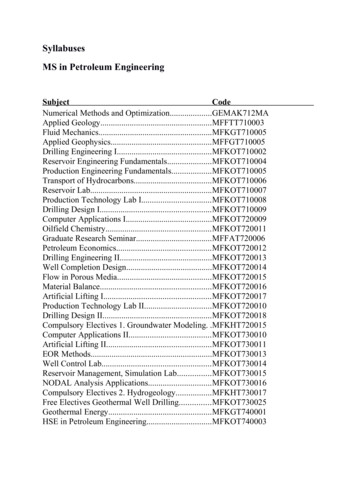
TECHNICAL RESOURCESCooling Tower Pumping and Piping››NPSH; CavitationIt is well known that fluids boil at defined temperature-pressure relationships. For any given fluid at a given temperature,pressure reduction to some stated value will cause boiling or vaporization.A pumped fluid can vaporize or flash within the pump itself because of inadequate pressurization. Fluid vaporization within thepump is generally defined as cavitation and can cause trouble as follows:1.Pump impeller damage will occur. This is because low pressures in the impeller “eye” will cause vapor bubble formation.The vapor bubbles then collapse or “implode” because of the pressure increase as the bubbles move into higher pressureareas inside the impeller. These hammer-like blows against the impeller can cause physical destruction within a shorttime.2.The pump curve will change drastically and in an unpredictable manner. Flow can virtually cease or “slug” because thepump cannot readily deliver both fluid and vapor.3.Pump shafts can be broken because of slugging of the impeller against alternate bodies of fluid, vapor, and air.4.Mechanical pump seal failure can occur because the mechanical seal is asked to work under intolerable conditions; vaporflash around the seal causes “dry” operation and rapid wear.It is most important to successful pump application that adequate (above vaporization) pressures be maintained within thepump.The engineering tool used to insure adequate anti-flash pressurization is a term defined as “Net Positive Suction Head” (NPSH).NPSH is a rather abstract term which has been subject to much misunderstanding. Before defining NPSH, it will be worthwhileto establish why the term is necessary.All pumps operate at a lower pressure in theimpeller eye and inlet to the impeller vanes thanthe pressure existing at the pump suction flange.Even though pressure at the pump suction flangeis measured and known to be above the flash orvaporization point, the pump can still cavitatebecause of the pressure reduction that exists fromthe suction flange to the pump interior.Internal pump pressure drop occurs because ofgreatly increased fluid velocities from the pumpsuction flange to and through the impeller eyeand because of turbulence, vane entrance frictionlosses, etc. In order to prevent cavitation, then, theapplication engineer must know how much internalpump pressure drop will occur for his designcircumstances and for any of a number of specificpump selection possibilities.Pressure At PumpSuction FlangePsImpellerFlowd alire EquuqRe PSHN -PVPSThe pump manufacturer’s measure of this pressurereduction is called “Required NPSH”.J132Q U E S T I O N S ? C A L L 4 1 0 . 7 9 9 . 6 2 0 0 O R V I S I T W W W. B A LT I M O R E A I R C O I L . C O MMinimum PressureInside Pump; AtImpeller Vane InletPVFigure 13. Required NPSH is Measure of Pump Pressure Drop
Test procedures for establishing Required NPSH havebeen standardized and are carefully followed by pumpmanufacturers so as to obtain as true an estimation ofinternal pump pressure drop as possible.Required NPSH is illustrated on pump curves by severaldifferent methods. Figure 14 shows a separate curve plot ofRequired NPSH. This type of illustration is used when only asingle pump capacity curve is shown.Regardless of the illustration method, Required NPSH isnot a constant value for any pump. Similar to valve pressuredrop, Required NPSH will increase with flow increase.Again, referencing to valves, it is well known that for a givenflow rate, a large valve will cause less pressure drop than asmaller valve. In a similar manner, pumps can be consideredas small or large by reference to impeller eye diameter forintended pumped flow rate. For the same pumped flow rate,a small pump (small impeller eye diameter) will have a muchhigher Required NPSH than a larger pump.Figure 14. Required NPSH Increases as Flow Increases Through PumpFigure 15 provides some important basic pump applicationpoints.1.Pumps selected to the end of the capacity curve (FtHd vs. GPM) are being driven to maximum capabilityand are the smallest pump that can provide designflow rate. The pump is “small” however, andestablishes a maximum Required NPSH (pumppressure drop).While generally lowest cost, because of minimumsize, the selection establishes maximum troublepotential.2.Pumps selected to the midpoint area of the capacitycurve are larger; impeller eye velocity is reduced andthe pump internal pressure drop must be lower.Figure 15. Difference in Required NPSH for Same Flow MostOften Determined b y Pump SizeThe pump so selected will cost more than the minimal “end of curve” selection but will reduce trouble potential when NPSH orcavitational problems are a consideration.It should be noted, in passing, that many potential pump application problems other than cavitation are reduced by midpointselection: flow balance, noise, etc.Reprinted with permission from Xylem, Inc. Copyright 2013.PRODUCT & APPLICATION HANDBOOK VOLUME VJ133
TECHNICAL RESOURCESCooling Tower Pumping and PipingWe have thus far established a basic point; that Required NPSH is a description of a specific pump’s internal pressure drop asflow rate through the pump changes. How is knowledge of Required NPSH used for specific pump application problems?The fundamental manner in which NPSH is used is simple and direct. An assessment is made by the application engineer as tothe pressure that will be available at the pump suction flange for the given fluid at design flow rate.The fluid temperature is also known, and vapor pressure tables define the pressure at which the fluid will boil.The difference between the available suction flange pressure and the fluid boiling point is then determined and defined as“Available NPSH”. Available NPSH is then the available suction flange pressure over and above the fluid boiling point pressure.What this means is that fluid will not flash or cavitate inside the pump so long as the internal pump pressure drop (RequiredNPSH) is less than Available NPSH.As an example, a system under design is intended to pump 212 F water. The application engineer states his conclusion, aftercalculation that the pump suction flange will be at 12 psig pressure during operation. What is the Available NPSH?Since 212 F water boils at 0 psig, the Available NPSH must be 12 psi; the pump suction flange pressure will be 12 psi abovethe fluid boiling point.Given that the pump internal pressure drop (Required NPSH) is only 8 psi, it will be known that the lowest possible internalpump pressure will still be 4 psi over the boiling point; the pump will not cavitate because Available NPSH is greater thanRequired NPSH.Supposing for this example that a pump is inadvertently selected which has a Required NPSH of 14 psi at design flow rate.This condition immediately establishes that the internal pump pressure will be below the boiling point; 12 - 14 - 2 psi. Theinternal pump pressure drop (Required NPSH) is greater than Available NPSH; pump cavitation will and must occur.The example illustrates the fundamental reasoning behind NPSH evaluation procedure. It will be noted, however, that theexample has stated NPSH as psi. This has been done only to clarify fundamental usage of the terms. NPSH, whether availableor required, is never expressed in psi terms. It is always stated in terms of ft fluid head.The reason NPSH is stated in terms of ft fluid head is because of the need for generalizatio
3. Air in pump suction; as caused by tower pan vortex, pan drain down or faulty bypass. 4. Unstable pump operational points as caused by: a. Improper application of tower bypass controls. b. High pressure drop tower spray nozzles in combination with tower bypass. 5. Inadequate maintenance procedures causing: a. Plugged suction strainer. b.