Transcription
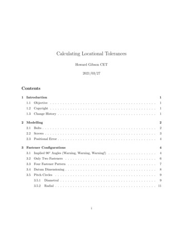
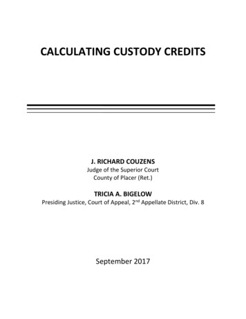
NEW LAYOUT:Layout 15/7/104:11 PMPage 61New CodeRequirements forCalculating Heat InputWelders, inspectors, and engineers should be aware of the changesto QW-409.1 of ASME IX regarding waveform-controlled weldingBY TERESA MELFIWelding waveforms are used to limitdistortion, weld open roots, and to control HAZ properties. Waveform controlis essential for common processes like uphill GMA pulse welding. Power sourcesthat support pulsing (GMAW-P, GTAWP, etc.) are the most common waveformcontrolled power sources. Those marketed as synergic, programmable, or microprocessor-controlled are also likely tosupport waveform-controlled welding.The correlation between heat inputand mechanical properties is blurredwhen heat input is calculated using current and voltage readings from conventional meters. This includes external meters and even those located on the welding power source. It’s not that the metersare incorrect — in fact, most are calibrated and tested to NIST standards.Rather, the inaccuracy involves the meansof capturing and displaying the data.Conventional DC meters display average voltage and average current. Conventional AC meters display RMS values. Toaccurately indicate the energy input to aweld, the voltage and current readingsmust be multiplied together at very rapidintervals that will capture brief changes inthe welding waveforms. This frequency isin the order of magnitude of 10,000 timesper second. Specialized meters are required to accomplish this.Revisions to ASME Section IX providea new method of calculating heat inputthat allows comparison of the heat inputfrom various welding power sources andvarious welding waveforms. This will allowproduction welding to take place with awelding procedure specification (WPS)that specifies either conventional or waveform-controlled welding, which is sup-ported by a procedure qualification record(PQR) using either conventional or waveform-controlled welding.Calculating Heat InputMany welding codes use the equationshown in Equation 1 to calculate heatinput. Because the welding process(GMAW, SAW, etc.) is an essential variable, a process or efficiency factor is notincluded in the heat input calculation.The new equations that will be in the 2010edition of ASME Section IX are shown inEquations 2 and 3, either of which givesequivalent results. Both equations areshown because some welding powersources and meters display energy values,and others display power values.Voltage Amperage 60Travel Speed (in./min or mm/min)Equation 1: Traditional heat input equation, ASME Section IX QW-409.1 (a).Energy (Joules)Weld Bead Length (in. or mm)Equation 2: New heat input equation formeters displaying energy measurement(Joules), ASME Section IX QW-409.1(c)(1).Power (Joules/s) Arc Time (s)Weld Bead Length (in. or mm)Equation 3: New heat input equation formeters displaying power measurement(Joules/s or W), ASME Section IXQW-409.1 (c)(2).Three examples from GMA weldingare shown in Fig. 1. The axial spray waveforms are essentially constant, and the difference between the measurement methods is minimal. For the two waveformcontrolled procedures, there is an errorbetween the measurement methods thatcan be in a positive or negative direction.It is clear from the significant differenceswhy a new measurement method isneeded.Changes in ASMESection IXASME codes and standards have along history, now in their 125th year. Therules for welding were removed from theconstruction codes when ASME SectionIX was published in 1941. ASME SectionIX has become a global standard, referenced by the ASME construction codes,owners, engineering firms, and other fabrication and construction codes.The ASME IX Standards Committeehas subcommittees that address procedureand performance qualifications, materials,general requirements, and brazing. Morethan three years ago, a task group wasformed to work on issues surrounding welding with complex waveforms from microprocessor-controlled power sources. Thefirst result of this group’s work will be achange to the measurement and calculation method for heat input.QW409.1 is the main Section IX variable that deals with heat input. Currently,there are two ways to calculate heat input.Method (a) is the traditional heat inputequation shown in Equation 1. Method(b) is a measurement of the volume ofTERESA MELFI is with The Lincoln Electric Co., Cleveland, Ohio. She is chair of the AWS A5B Committee on submerged arc welding,a member of the AWS A5 Committee on filler metal specifications, a member of ASME Section IX, including the materials subgroup and aworking group on advanced waveform welding, and is the U.S. delegate to the International Institute of Welding commission that covers pressure vessels, boilers, and pipelines.WELDING JOURNAL61
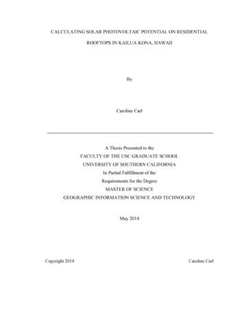
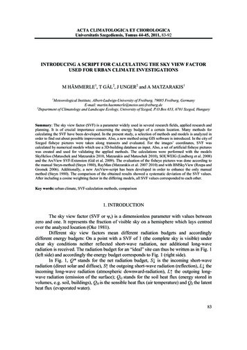
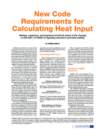
NEW LAYOUT:Layout 15/7/104:11 PMPage 62Fig. 2 — With the proper software installed,access to the energy reading entails pressingthe menu option “Display Energy.”Fig. 1 — Heat input differences calculated using Equation 1 vs. Equation 2.weld metal deposited. A new method (c)is added in the 2010 edition, which includes Equations 2 and 3.Any of the methods can be used whenwelding following procedures that are notwaveform controlled. When welding following waveform-controlled procedures,only methods (b) or (c) are permitted.With these methods, it is possible to determine the compliance of a productionweld made using a waveform-controlledwelding procedure to an existing qualifiedprocedure, even when the procedure qualification was performed using nonwaveform controlled welding. An appendix toASME Section IX has been provided to62JUNE 2010guide users through these code changes.The appendix provides guidance with newprocedure qualifications, existing qualified procedures, and comparing heat inputs between waveform-controlled andnonwaveform-controlled welding. ASMESection IX does not mandate separateperformance qualifications for waveformcontrolled welding.How to Comply withASME Code ChangesTo use method (c) of the code, a reading of energy (Joules) or power (Joules/s)Fig. 3 — The real-time energy is continuously incremented while welding, and thefinal energy is displayed until the next arcstart.must be obtained using a meter that captures the brief changes in a welding waveform and filters out extraneous noise. Thesimplest place to obtain this is from thewelding power source. Many powersources that output pulsing waveforms willdisplay these readings, although somemight require software upgrades to enable this. Details and software upgradesfor Lincoln Electric’s Powerwave “M” series and several other models are available free of charge at www.powerwave
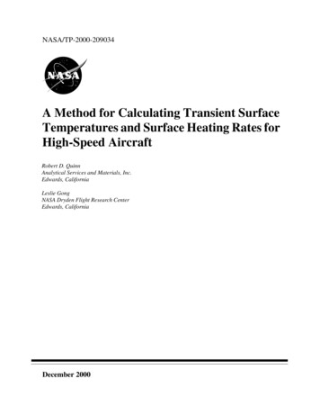
NEW LAYOUT:Layout 15/7/104:11 PMPage 63Assist Chart for ASME IX QW-409.PQRPQR qualifiedq u a lifie d wwith:ith :Non-waveformNon-waveformcontrolled weldingw e ld in gcontrolledusing conventionalc o n v e n tio n a lusingvvolto lt and ammetersa m m e te rsandand QW-409.1(a)Q W -4 0 9 .1 (a )andN o n -w a v e fo rmNon-waveformcontrolledweldingc o n tr o lle d we ld in gusingusing instantaneousin s ta n ta n e o u senergypowerenergy oror power andaQWQW4 0 9 .1 (c )QW-409.1(c)WaveformWaveform ccontrolledo n tr o lle dwe ld in g us in gweldingusingiinstantaneousn s ta n ta n e o u s en e rg yenergyor pow er and QWWorpowerandQW4 0 9 .1 (c )409.1(c)WaveformWaveform controlledc o n tr o lle dwelding usingu s in gweldingcconventionalonventional voltvolt andandam m e te rs and QWWammetersandQW409.1(a) ((qualifiedq u a lifie d409.1(a)prior ttoo2010 ccodeodeprior2010cchange)hange)QQualifiesualifies forfo r wweldselds producedproduced with:w ith : Non-waveform controlledcontrolled powerpower supplysupply usingusing conventionalconventional voltvolt metersmeters andand ammetersammeters andand QW-409.1(a).QW-409.1(a).Non-waveform Non-waveform controlledc o n tr o lle d power supplysupply displayingdisplaying instantaneousin s ta n ta n e o u s en e rg y oow er me a s u re m e n t and QW-409.1(c).Q W -4 0 9 .1 (c ) .Non-waveformpowerenergyorr ppowermeasurementand Waveform ccontrolledo n tr o lle d power supplysupply displayingdisplaying instantaneousinstantaneous energyenergy oror powerpower measurementmeasurement andand QW-409.1(c).Q W -4 0 9 .1 (c ).Waveformpower Waveform ccontrolledo n tr o lle d power ssupplyupply whichwhich doesdoes notnot displaydisplay iinstantaneousnstantaneous energyenergy oror powerpower measurementmeasurement usingu s in gWaveformpowerexternal metersmeters tthathat display iinstantaneousn s ta n ta n e o u s power oror energyenergy measurementsm e a s u re m e n ts and QW -4 0 9 .1 (c ).externaldisplaypowerandQW-409.1(c). Non-waveform controlledcontrolled powerpower supplysupply usingusing conventionalconventional voltvolt metersmeters andand ammetersammeters andand QW-409.1(a).QW-409.1(a).Non-waveform Non-waveformpowerenergypowerandNon-waveform controlledc o n tr o lle d power ssupplyupply displayingdisplaying instantaneousin s ta n ta n e o u s energy oror power measurementm e a s u re m e n t and QW-409.1(c).Q W -4 0 9 .1 (c ). WaveformpowerWaveform ccontrolledo n tr o lle d power supplysupply displayingdisplaying instantaneousinstantaneous energyenergy oror powerpower measurementmeasurement andand QW-409.1(c).Q W -4 0 9 .1 (c ). WaveformpowerpowerWaveform ccontrolledo n tr o lle d power ssupplyupply whichwhich doesdoes notnot displaydisplay iinstantaneousnstantaneous energyenergy oror power measurementmeasurement usingu s in gexternaldisplaypowerandQW-409.1(c).external metersmeters tthathat display iinstantaneousn s ta n ta n e o u s power oror energyenergy measurementsm e a s u re m e n ts and QW -4 0 9 .1 (c ). Non-waveform controlledcontrolled powerpower supplysupply usingusing conventionalconventional voltvolt metersmeters andand ammetersammeters andand QW-409.1(a).QW-409.1(a).Non-waveform Non-waveform controlledc o n tr o lle d power ssupplyu p p ly displaying instantaneousin s ta n ta n e o u s energy oror power measurementm e a s u re m e n t and QW-409.1(c).Q W -4 0 9 .1 (c ).Non-waveformpowerdisplayingenergypowerand Waveform ccontrolledo n tr o ll e d power supplysupply displayingdisplaying instantaneousinstantaneous energyenergy oror powerpower measurementmeasurement andand QW-409.1(c).Q W -4 0 9 .1 (c ).Waveformpower Waveform ccontrolledo n tr o lle d power ssupplyupply whichwhich doesdoes notnot displaydisplay instantaneousin s ta n ta n e o u s en e rg y oower measurementmeasurement usingu s in gWaveformpowerenergyorr ppowerexternal metersmeters tthathat display iinstantaneousn s ta n ta n e o u s power oror energyenergy measurementsm e a s u r e m e n ts and QW -4 0 9 .1 (c ).externaldisplaypowerandQW-409.1(c). Non-waveform controlledc o n tr o lle d power supplysupply usingusing conventionalconventional voltvolt metersmeters andand ammetersammeters andand QW-409.1(a).QW-409.1(a).Non-waveformpower Non-waveform ccontrolledo n tr o lle d power ssupplyu p p ly displaying instantaneousin s ta n ta n e o u s en e rg y oow er me a s u re m e n t and QW -4 0 9 .1 (c ).Non-waveformpowerdisplayingenergyorr ppowermeasurementandQW-409.1(c). Waveform ccontrolledo n tr o lle d power supplysupply displayingdisplaying instantaneousinstantaneous energyenergy oror powerpower measurementmeasurement andand QW-409.1(c).Q W -4 0 9 .1 (c ).Waveformpower Waveform ccontrolledo n tr o lle d power ssupplyu p p ly which doesdoes notnot displaydisplay iinstantaneousn s ta n ta n e o u s en e rg y oower measurementmeasurement usingu s in gWaveformpowerwhichenergyorr ppowerex te rn a l meters tthathat display iinstantaneousn s ta n ta n e o u s power oror energy measurementsm e a s u re m e n ts and QW -4 0 9 .1 (c ote: IInn ssomeome ccases,ases, itit mightmight benefitbenefit thethe useruser toto append a PQR toto showshow thethe heatheat inputinput ccalculateda lc u la te d using iinstantaneousn s ta n ta n e o u sNote:PQRusingpower on e rg y . This ccanan be donedone byby weldingwelding a simplesimple beadbead onpla te using thethe ssameam e parameters ((modem ode oro g ra m ,powerorr eenergy.Thisbeonplateusingparametersorr pprogram,vvoltage,oltage, ccurrent,u rre n t, etc)c) as werewere usedused inin tthehe procedure qualification.q u a lific a tio n . Utiliz in g eith e r a we ld in g power ssourceource oror externale x te rn a letc)asprocedureUtilizingeitherweldingpowermeter tthathat displays iinstantaneousn s ta n ta n e o u s energy oror power, thethe heatheat inputinput maymay bebe calculatedc a lc u la te d per QW--409.1(c) bWased on asedonrreadings.e a d in g s .welding may be used to support weldingwith waveform or nonwaveform-controlled procedures and QW-409.1(a) orQW-409.1(c). This can be downloadedfrom www.lincolnelectric.com.SummaryFig. 4 — The heat input is calculated by taking the final energy value and dividing it by thelength of the weld.software.com. For a power source thatdoesn’t support the display of energy orpower, external meters are available. Ameter with demonstrated accuracy in thisapplication is the Fluke 345 Power Quality Clamp Meter.With the proper software installed, itis simple to access the energy reading —Fig. 2. In the setup menu, enable the option to “Display Energy.” When an arc isstarted, the energy value will begin to increment. The value will continue to increase, showing the real-time energy putinto that weld — Fig. 3. When the welding stops, the final energy value will bedisplayed until welding resumes again.This value represents the amount of energy that went into that weld, from arcstart to arc stop.To calculate the heat input, the finalvalue is simply divided by the length of theweld — Fig. 4. In this case, the heat inputwould be 22.3 kJ/3.6 in., or 6.2 kJ/in.A detailed matrix has been developedshowing how a PQR qualified with eitherwaveform or nonwaveform-controlledThe ASME Section IX welding andbrazing standard is widely used by publicagencies and private companies conc
Calculating Heat Input Many welding codes use the equation shown in Equation 1 to calculate heat input. Because the welding process (GMAW, SAW, etc.) is an essential vari-able, a process or efficiency factor is not included in the heat input calculation. The new equations that will be in the 2010 edition of ASME Section IX are shown in