Transcription
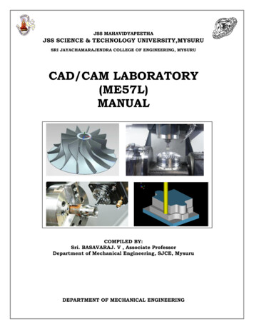
JSS MAHAVIDYAPEETHAJSS SCIENCE & TECHNOLOGY UNIVERSITY,MYSURUSRI JAYACHAMARAJENDRA COLLEGE OF ENGINEERING, MYSURUCAD/CAM LABORATORY(ME57L)MANUALCOMPILED BY:Sri. BASAVARAJ. V , Associate ProfessorDepartment of Mechanical Engineering, SJCE, MysuruDEPARTMENT OF MECHANICAL ENGINEERING
JSS MAHAVIDYAPEETHAJSS SCIENCE & TECHNOLOGY UNIVERSITY,MYSURUSRI JAYACHAMARAJENDRA COLLEGE OF ENGINEERING, MYSURUStudent NameRoll NumberUniversity SeatNumberSectionBatch NumberLab TimingsInternal Assessment Marks Awarded : out of 501.2.Signature of the Staff-in-chargeSignature of theHead of the Department
JSS MAHAVIDYAPEETHAJSS SCIENCE & TECHNOLOGY UNIVERSITY,MYSURUSRI JAYACHAMARAJENDRA COLLEGE OF ENGINEERING, 5.Title of theExperimentPage No. MarksAwardedInitials ofthe Teacher
Vision of the DepartmentDepartment of mechanical engineering is committed to prepare graduates, post graduates andresearch scholars by providing them the best outcome based teaching-learning experience andscholarship enriched with professional ethics.Mission of the DepartmentM-1: Prepare globally acceptable graduates, post graduates and research scholars for their lifelonglearning in Mechanical Engineering, Maintenance Engineering and Engineering Management.M-2: Develop futuristic perspective in Research towards Science, Mechanical Engineering MaintenanceEngineering and Engineering Management.M-3: Establish collaborations with Industrial and Research organizations to form strategic andmeaningful partnerships.
CAD/CAM LABORATORYSubject Code: ME57LNo. of Credits: 0- 0 – 1.5No. of Lecture Hours / Week: 04Exam Hours: 3Total No. of Lecture Hours: 48Exam Marks: 100COURSE OBJECTIVES: To impart the students with necessary computer aided modeling skills using standard CADpackages.To expose the students to the techniques of CNC programming and cutting tool path generationthrough CNC simulation software by using G-Codes and M-codes and writing part program forsimple machine parts.COURSE CONTENTPART – ACOMPUTER AIDED DESIGNStudy of Solid modeling Package (UG-NX). Solid Modeling of simple machine parts andassembly.10 Exercises20 HoursPART – BCOMPUTER AIDED MANUFACTURINGWriting of manual part programming using ISO codes for turning and milling operations. Use oftool radius compensation and canned cycles. Check the program for syntax errors, lists errorsand locations, show the tool path through graphical simulation using EXSL-WIN or other CAMPackages.Modelling of simple machine parts (Turning and Milling) and generating machine codes usingstandard NX CAM or other CAM Packages28 HoursCOURSE OUTCOMESUpon completion of the course, students shall be able to:CO1 : Modeling of simple machine parts and assemblies from the part drawings using standardCAD packages.CO2 : Generate CNC Turning and Milling codes for different operations using standard CAMpackages. Write manual part programming using ISO codes for turning and millingoperations
BRIEF HISTORY OF CAD/CAM DEVELOPMENTThe roots of current CAD/CAM technologies go back to the beginning of civilization whenengineers in ancient Egypt recognized graphics communication. Orthographic projectionpracticed today was invented around the 1800’s. The real development of CA D/CAM systemsstarted in the 1950s. CAD/CA M went through four major phases of development in the lastcentury. The 1950’s was known as the era of interactive computer graphics. MIT’s ServoMechanisms Laboratory demonstrated the concept of numerical control (NC ) on a three-axismilling machine. Development i n this era was slowed down by the shortcomings of computersat the time. During the late 1950’s the development of Automatically Programmed Tools (APT)began and General Motors explored the potential of interactive graphics.The 1960s was the most critical research period for interactive computer graphics. IvanSutherland developed a sketch pad system, which demonstrated the possibility of creatingdrawings and altercations of objects interactively on a cathode ray tube (CRT). The term CADstarted to appear with the word ‘design’ extending beyond basic drafting concepts. GeneralMotors announced their DAC-1 system and Bell Technologies introduced the GRAPHIC 1remote display system.During the 1970’s, the research efforts of the previous decade in computer graphics had begun tobe fruitful, and potential of interactive computer graphics in improving productivity was realizedby industry, government and academia. The 1970’s is characterized as the golden era forcomputer drafting and the beginning of ad hoc instrumental design applications. NationalComputer Graphics Association (NCGA) was formed and Initial Graphics ExchangeSpecification (IGES) was initiated.In the 1980’s, new theories and algorithms evolved and integration of various elements of designand manufacturing was developed. The major research and development focus was to expandCAD/CAM systems beyond three-dimensional geometric designs and provide more engineeringapplications.The present day CAD/CAM development focuses on efficient and fast integration andautomation of various elements of design and manufacturing along with the development of newalgorithms. There are many commercial CAD/CAM packages available for direct usages that areuser-friendly and very proficient.Below are some of the commercial packages in the present market.AutoCAD and Mechanical Desktop are some low-end CAD software systems, which aremainly used for 2D modeling and drawing. NX, Pro-E, CATIA and I-DEAS are high-end modeling and designing software systems thatare costlier but more powerful. These software systems also have computer aidedmanufacturing and engineering analysis capabilities. ANSYS, ABAQUS, NASTRAN, Fluent and CFX are packages mainly used for analysis ofstructures and fluids. Different software are used for different proposes. For example,Fluent is used for fluids and ANSYS is used for structures.
Alibre and CollabCAD are some of the latest CAD systems that focus on collaborative design,enabling multiple users of the software to collaborate on computer-aided design over theInternet. DEFINITION OF CAD/CAM/CAEComputer Aided Design – CADCAD is technology concerned with using computer systems to assist in the creation,modification, analysis, and optimization of a design. Any computer program that embodiescomputer graphics and an application program facilitating engineering functions in designprocess can be classified as CAD software.The most basic role of CAD is to define the geometry of design – a mechanical part, aproduct assembly, an architectural structure, an electronic circuit, a building layout, etc. Thegreatest benefits of CAD systems are that they can save considerable time and reduce errorscaused by otherwise having to redefine the geometry of the design from scratch every time it isneeded.Computer Aided Manufacturing – CAMCAM technology involves computer systems that plan, manage, and control themanufacturing operations through computer interface with the plant’s production resources.One of the most important areas of CAM is numerical control (NC). This is the technique ofusing programmed instructions to control a machine tool, which cuts, mills, grinds, punches orturns raw stock into a finished part. Another significant CAM function is in the programming ofrobots. Process planning is also a target of computer automation.Computer Aided Engineering – CAECAE technology uses a computer system to analyze the functions of a CAD-created product,allowing designers to simulate and study how the product will behave so that the design can berefined and optimized.CAE tools are available for a number of different types of analyses. For example, kinematicanalysis programs can be used to determine motion paths and linkage velocities in mechanisms.Dynamic analysis programs can be used to determine loads and displacements in complexassemblies such as automobiles. One of the most popular methods of analyses is using a FiniteElement Method (FEM). This approach can be used to determine stress, deformation, heattransfer, magnetic field distribution, fluid flow, and other continuous field problems that areoften too tough to solve with any other approach.
STARTING NX7 SESSION AND OPENING FILESOpen NX7 SessionFrom the Windows desktop screen, click on Start Programs UGS NX 7.5 NX 7.5The main NX7 Screen will open. This is the Gateway for the NX7 software. The NX7 blankscreen looks like the figure shown below. There will be different tips displayed on the screenabout the special features of the current version. The Gateway also has the Standard Toolbar thatwill allow you to create a new file or open an existing file. On the left side of the Gatewayscreen, there is a Toolbar called as Resource Bar that has menus related to different modulesand the ability to define and change the ‘Role’ of the software, view ‘History’ of the softwareuse and so on. This will be explained in detail later in this chapter. Let’s begin by learning howto open a part file in NX7.
To create a new file there are two options. You can click on the ‘New’ tab on top of the screenor go through the ‘File’ drop-down menu.Open a New FileOn the menu bar found at the top-left of the screen, click FILENEWThis will open a new session, asking for the name and location of the new file to be created asshown at the bottom left. You need to select the units (inches or millimeters) of the workingenvironment by clicking on the drop-down menu on the top right corner. The default ismillimeters. However, most of the material in the tutorials is modeled in inches. So always,be sure to select inches before creating a new .prt file unless otherwise specified. You can alsoselect the type of the file you want to create – either a part file or an assembly file or sheet-metalfile – by selecting the file type as shown in Templates dialogue box located at the center of the
window. The properties of the selected file are displayed below the Preview on the middle rightcorner.Enter the location of the file and then and click OKOpen a Part FileClick FILE OPENYou can also click the Open icon from the Standard toolbar at the top of the screen.The Open Part File dialog will appear. You can see the preview of the files on the right side of thewindow. You can disable the Preview by un-clicking the box in front of the Preview button.Click CANCEL to exit the window
How to use the constraints toolDraw the sketch shown below:Sketch you need to drawOnce the sketch is complete, we will constrain the sketch. It is better to applythegeometric constraints before giving the dimensional constraints. Choose INSERT CONSTRAINTS or click on the Constraints icon in the side toolbarYou will be able to see all the degrees of freedom on the screen represented by orange arrows.orange color arrows are the no of DOF to be constrained
We will start by constraining between an entity in the sketch and the datum or fixed reference.As an example, we will place the center of the arc at the origin. We can use the two defaultX and Y axes as a datum reference. Select the Y-axis and then the center of the arc, which is marked by the intersection ofthe yellow arrows. The center of the arc will be marked by a red asterisk once it hasbeen selected Click the Point on Curve icon Repeat the same procedure to place the center of the arc on the X-axis Select the two slanted lines and make them equal in length Similarly select the two long vertical lines and make them equal in length
Select the bottom two horizontal lines and make them collinear and then click on the same linesand make them equal in lengthIf you DO NOT find the two Blue circles (Tangent Constraints) near the semicircle as shownin the figure, follow the below steps. Otherwise, you can ignore this and skip down tothe dimensional constraints. Select the circular arc and one of the two vertical lines connected to its endpoints Select the Tangent iconIf the arc and line is already tangent to each other, the icon will be grayed out. If that is thecase click on EDIT SELECTION , DESELECT ALL. Repeat the same procedure for the
arc and the other vertical line. Select the two vertical lines and make them equal Similarly select the two small horizontal lines and make them collinear and equal Similarly select the two vertical lines and make them equal
So far, we have created all the geometric constraints. Now we have to create thedimensional constraints. You will find that as we add on dimensions, the degrees of freedomrepresented by the yellow arrows will disappear.It is always better to apply the geometry constraints first. If there is any conflict between thedimensional and geometric constraints, thoseentities will be highlighted in yellow. Choose the Inferred Dimensions icon in the Constraints toolbar Add on all the dimensions as shown in the following figureFor example, to create a dimension for the top two corners, you may have to click on thearrow next to the Inferred Dimensions icon and click on the Horizontal icon. Then clicksomewhere near the top of the two diagonal lines to select them. While dimensioning, if you findthe dimensions illegible, but do not worry about editing the dimensions now. Make sure thesmall arrows are disappearing as constraints are placed.
All dimensions are given after Geometrical ConstraintsNow we will edit all the dimension values one by one. It is highly recommended to startediting from the biggest dimension first and move to the smaller dimensions. Edit the values as shown in the figure below. Double click on each dimension to changethe values to the values as shown in figure below:Fully Constrained Sketch Click on the Finish flag on the top left corner of the screen when you are finished
PrimitivesThey let you create solid bodies in theform of generic building shapes.Primitives include, Block Cylinder Cone Sphere Primitives are the primary entities. Hence we will begin with a short description of primitivesand then proceed to modeling various objects.PRIMITIVESPrimitive features are base features from which many other features can be created. The basicprimitives are blocks, cylinders, cones and spheres. Primitives are non-associative which meansthey are not associated to the geometry used to create them. The parameters of these primitiveobjects can be changed.Now let us start modeling of some basic objects.Model a BlockCreate a new file and name it asArborpress plate.prtNow let us model a plate.Choose INSERT DESIGN FEATURE BLOCK or click on the Block icon in theForm Feature ToolbarThe Block window appears. There are three mainthings to define a block. They include the Type,Origin and the Dimensions of the block. To accessthe Types scroll the drop-down menu under Type.There are three ways to create a block primitive.
Origin, Edge Lengths Height, Two Points Two Diagonal Points Make sure the Origin, Edge Lengths methodis selectedNow, we will choose the origin using the PointConstructor.Click on the POINT CONSTRUCTOR iconunder the OriginorClick on the POINT CONSTRUCTOR icon in the Utility Toolbar as shown in thefollowing figure.The Point Constructor box will open. The XC, YC, ZC points should have a default value of 0.Click OKThe Block window will reappear.Type the following dimensions in thewindow.Length (XC) 65 inchesWidth (YC) 85 inchesHeight (ZC) 20 inchesClick OKIf you do not see anything on the screen, right-click and select FIT. You can also press Ctrl F
Right-click on the screen and click on ORIENT VIEW TRIMETRICYou should be able to see the complete plate solid model. Save and close the part file.
Model a ShaftAfter modeling a basic block, we will now model ashaft having two cylinders and one cone joined together.Create a new file and save it as Impeller shaft.prtChoose INSERT DESIGN FEATURE CYLINDERSimilar to the Block there are three things that need tobe defined to create a cylinder, Type, Axis & Origin,Dimensions.A Cylinder can be defined by two types which can beobtained by scrolling the drop-down menu under TypeAxis, Diameter, Height Arc, Height Select AXIS, DIAMETER, HEIGHT Click on the Vector Constructor icon next to SpecifyVector as shown on the second figure on right. Click on the ZC Axis icon. Leave the other options as default and click OK Click on the Point Constructor icon next toSpecify Point to set the origin of the cylinder Set all the XC, YC, and ZC coordinates to be 0You can see that the selected point is the origin of WCSIn the next dialog box of the window, type in thefollowing values as shown in figureDiameter 4 inchesHeight 18 inchesClick OK
Click CANCEL on any other windows that appearRight-click on the screen, choose ORIENT VIEW ISOMETRICYou can change the color of the solid body and the background as mentioned in the Chapter2.3.4. The cylinder will look as shown below.Now we will create a cone at one end of the cylinder.Choose INSERT DESIGN FEATURE CONESimilar to Block and Cylinder there are various waysto create a cone which can be seen by scrolling thedrop-down menu in the Type box. Diameters, Height Diameters, Half Angle Base Diameter, Height, Half Angle Top Diameter, Height, Half Angle Two Coaxial Arcs Select DIAMETERS, HEIGHT Click on the Vector Constructor icon next to SpecifyVector. Choose the ZC-Axis icon so the vector is pointing inthe positive Z direction Click OK Click on the Point Constructor icon next to Specify Point to set the origin of the cylinder.The Point Constructor window will appear next.
Choose the Arc/Ellipse/Sphere Center icon onthe dialog box and click on the top circular edge ofthe cylinderORFor the Base Point coordinates, type in thefollowing values: XC 0 YC 0 ZC 18Click OKIn the cone window, type in the following values:Base diameter 4 inchesTop Diameter 6 inchesHeight 10 inchesClick OKOn the Boolean Operation window, chooseUNITENow the cone will appear on top of the cylinder.Click CANCEL on any other windowsPress Ctrl F OR right-click and select FITThe shaft is as shown on right.Now we will create one more cylinder on top of the cone.Repeat the same procedure as before to create another Cylinder.The vector should be pointing in the positive ZC-direction. On thePoint Constructor window, again click on the Center icon andconstruct it at the center point of the base of the cone. Thecylinder should have a diameter of 6 inches and a height of 20inches.The complete shaft will look as shown below. Remember to save the model.
Creating a solid model using EXTRUDE commandExtrude is defined as the process of creating a feature from a sketch by adding the materialalong the direction normal to the sketch or any other specified direction.Above Figure shows the isometric view of a closed sketchand above Figure shows the extruded feature created using this sketch.When you invoke the Extrude tool, the Extrude dialog box will be displayed, as shownin Figure
You will be prompted to select the planar face to sketch or the section geometry to beextruded. If you select the sketch at this stage, the preview of the extruded featurecreated using the default values will be displayed on the screen. If you select the sketchplane, the Sketcher environment will be invoked. Draw the sketch and exit the Sketcherenvironment; thepreview of the extruded feature will be displayed in the Modeling environment.Extrude Dialog Box OptionsThe options in this dialog box are discussed next.Section RolloutThe options in this rollout are used to sketch the section or select the section. By default,boththe Sketch Section and Curve buttons will be chosen in this rollout and you will be promptedto select the planar face to sketch or the section geometry to be extruded. These options arediscussed next.Sketch SectionThis button is used to draw the sketch for extrusion. When you choose this button, the CreateSketch dialog box will be displayed and you will be prompted to select the object for thesketch plane. You can select a datum plane or the face of a solid body as the sketching plane.CurveBy default, this button is also chosen from the Section rollout and it is used to selectthe already drawn section sketch.Direction RolloutBy default, the direction of extrusion will be normal to the selected section. The buttonsin this rollout are used to define the direction of extrusion. These options are discussed next.Vector ConstructorIf you choose this button, the Vector dialog box will be displayed. You can specifythe extrude direction using this dialog box.Inferred Vector Drop-down ListThis drop-down list is used to specify the direction of extrusion. The default directionis normal to the selected section.Reverse DirectionThis button is chosen to flip the current extrusion direction.
Limits RolloutThe options in this rollout are used to specify the start and termination of the extrusion.These options are discussed next.Start Drop-down ListThis drop-down list allows you to specify the start point of the extrusion. You can selectthe Value and Symmetric Value options from this drop-down list. The Value option allowsyou to specify the distance from the sketching plane at which the extruded feature will start.You need to enter this value in the Distance edit box. If you enter a positive value, it will betaken as the offset value between the sketch and the start of the extrusion feature. If you enter0,the extruded feature will start from the sketch plane. If you enter a negative value,the extruded feature will start from below the sketch plane. The Symmetric Value optionallows you to extrude the sketch symmetrically in both the directions of the currentsketching plane. When you select this option, the edit boxes on the right of the Start and theEnd edit boxes will show identical values and the preview will also be modified dynamically.Figure shows the preview of a sketch being extruded symmetrically in both the directions.Preview of the symmetric extrusionEnd Drop-down ListThis drop-down list allows you to specify the extrusion termination in thedirection of extrusion. For the base feature, only the Value and Symmetric Value options willbe available in this drop-down list. By default, the Value option will be selected, and thevalue entered last will be displayed in the Distance edit box. As a result, the sketch will beextruded only in the specified direction. Note that you need to enter a positive value in theDistance edit box.Figure shows the preview of the extrusion in only one direction
Figure shows the preview of the extrusion with different values in both directions. In thisfigure,the extrusion value in the upward direction is 10 and in the downward direction is -5.Boolean RolloutOptions in this rollout allow you to select the boolean operation that you need toperform. These options in this rollout are discussed in the next chapter.Draft RolloutThe options in this rollout are used to specify a draft angle to the extrusion feature.The options in this area will be available only when you select the section to extrude. Variousdraft options in this rollout are discussed next.AngleThis edit box allows you to specify the draft angle.DraftThis drop-down list allows you to specify the type of draft to be applied to the feature.The options in this area are discussed next.From Start LimitThis option adds the draft from the start section to the end section of the extruded feature. Asa result, the dimension of the feature at the start section is the same as that of the originalsketch and it tapers toward the end section.Figure shows thepreview of the extruded feature drafted using this option.
It is evident from this figure that the bottom section of the extruded feature is the same as thatof the original sketch and the feature tapers as it goes toward the top section.From SectionThis option is used to taper the extruded surface in such a way that the cross-section of theextruded feature remains the same at the sketching plane, as shown in FigureFrom Section - Symmetric AngleThis option is available only when you select the Symmetric Value option from the Limitsrollout or specify the values in both the start and the end directions. This option adds asymmetric taper in both directions of the sketch, as shown in Figure.
In this draft type, if the distance value in one of the directions is more than the other, thesection in that direction will also be smaller in size.From Section - Matched EndsThis option is also available only when you select the Symmetric Value option fromtheLimits rollout or specify the values in both the start and the end directions. Thisoptiontapers the modelsuch that the end sections in both the directions are of similar size,irrespective of the distance values in both directions, as shown in FigureFrom Section - Asymmetric AngleThis option is also available only when you select the Symmetric Value option fromtheLimits rollout or specify the values in both the start and the end directions. This option addsdifferent tapers in both directions of the sketch, as shown in Figure
When you select this option, the Front Angle and Back Angle edit boxes will beavailable in the Draft rollout. The front and back angle values will be applied at the front andback sides of the sketching planes used to create the extruded feature.Offset RolloutNX also allows you to create thin base features by extruding open or closed sketches.For example, refer to the closed sketch shown in FigureA thin feature created using this sketch is shown in Figure
Similarly, Figure shows an open sketchand Figure shows the resulting thin feature.
Two-SidedThis option is used to create a thin feature by offsetting the sketch in two directions.Selectthis option; the Start and End edit boxes will be displayed. If you enter the positive value inthe End edit box, the sketch will offset outward and vice-versa.Figure shows the preview of a thin feature with an offset only in the end directionand Figure shows the preview of the same feature with an offset in both the directionsSingle-SidedThis option will be enabled only when you create a thin feature using a closed sketchwith nonested closed sketch in it. If you select this option, the inner portion of the sketchwill be filled automatically. As a result of this, there will be no cavity inside the model. Itwill be similar to the solid extrusion from inside. However, you can also add some offsetto the outer side of the sketch.SymmetricThis option is used to offset the material symmetrically on both sides of the sketch to createthe thin feature.Settings RolloutThe options in this rollout are used to specify whether you need the extruded feature to be
a sheet body or a solid body. To get a solid body, the section must be a closed profile or anopen profile with an offset. If you use a Single-Sided offset, you will not be able to get asheet body.You can select the required option from the Body Type drop-down list.Preview Rollout This rollout is used to preview the model dynamically while modifying thevalues in the Extrude dialog box. If you select the Preview check box, it will allow you todynamically preview the changes in the model as you modify the values of the extrusion. TheShow Result button is used to view the final model. The Undo Result button is used to goback to the preview mode.After setting the values in the Extrude dialog box, choose OK to create the extrudedfeature and exit the dialog box. If you need to extrude more than one sketches, choose theApply button; the selected sketch will be extruded and the dialog box will be retained. Also,you will be prompted to select the section geometry. Select the other sketch to extrude andchoose the OK button.You can also set and modify the values of extrusion using the drag handles that willbe displayed in the preview of the extrusion feature, refer to Figure.The start drag handlewill be a filled circle and the end drag handle will be an arrow. Tomodify the start limit, end limit, or draft angle values, click on their respective drag handles,and then press and hold the left mouse button and drag the mouse. You can also enter the newvalues in the edit boxes that will be displayed after clicking on the respective handles. Tomodify the type of limits or taper, right-click on their respective drag handles and select thetype from the shortcut menu.
Creating a solid model using REVOLVE commandThe Revolve tool allows you to create a solid body by revolving a sketch around therevolution axis, which could be a sketched line or an edge of an existing feature. Figurebelow shows a sketch for the revolved feature andFigure shows the Isometric view of the resulting feature revolved through an angle of 270degree.To convert a sketch into a revolved body, you need to invoke the Revolve tool. This toolworks in the following three steps:Step 1: Select the sketch to be revolvedStep 2: Select the revolution axisStep 3: Specify the revolution parametersTo invoke the Revolve tool, choose the revolve button in the Feature dialog box; theRevolve dialog box will be displayed, as shown in Figure
click on the picture to enlargeThe options in this dialog box are same as the options in the Extrude dialog box, except theones that are explained next.Axis RolloutThe options in this rollout are used to specify the revolution axis. These options are discussednext.Specify VectorThe options in this area are used to specify the revolution axis using the VectorConstructor button or the Inferred Vector drop-down list.Vector ConstructorWhen you choose this button, the Vector dialog box will be displayed. You can specifythe revolution axis by using this dialog box.Inferred VectorThis drop-down list is a shortcut to specify the revolution axis.Reverse DirectionYou can choose this button to flip the direction of revolution.Specify PointThe options in this area ar
Computer Aided Design – CAD CAD is technology concerned with using computer systems to assist in the creation, modification, analysis, and optimization of a design. Any computer program that embodies computer graphics and an application program faci

