Transcription
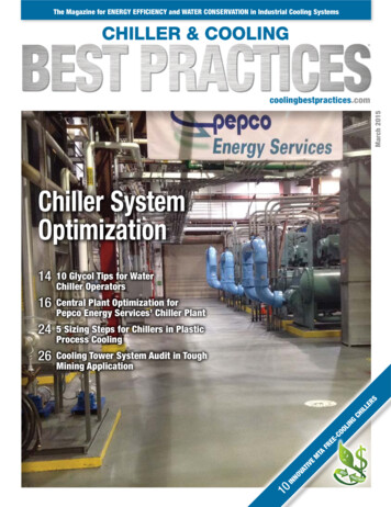
AquaSnap 30RAP010-150Liquid Chillerswith Puron Refrigerant (R-410A)50/60 HzInstallation InstructionsCONTENTSSAFETY CONSIDERATIONSPageSAFETY CONSIDERATIONS. . . . . . . . . . . . . . . . . . . . .1,2INSTALLATION. . . . . . . . . . . . . . . . . . . . . . . . . . . . . . . . 2-59Storage . . . . . . . . . . . . . . . . . . . . . . . . . . . . . . . . . . . . . . . . . . 2Step 1 — Place and Rig the Unit. . . . . . . . . . . . . . . . . . 2 PLACING UNIT RIGGING MOUNTING UNITStep 2 — Check Compressor Mounting . . . . . . . . . 11Step 3 — Connect Cooler Fluid andDrain Piping. . . . . . . . . . . . . . . . . . . . . . . . . . . . . . . . . . 11 ALL UNITS VICTAULIC COUPLING INSTALLATION UNITS WITH FACTORY-INSTALLEDHYDRONIC PACKAGES AIR SEPARATIONStep 4 — Fill the Chilled Water Loop . . . . . . . . . . . . 25 WATER SYSTEM CLEANING FILLING THE SYSTEM PUMP VFD SENSORLESS CONTROL (CLOSED LOOP) —ACTIVE SETUP 1 REMOTE SENSOR (CLOSED LOOP) —ACTIVE SETUP 2 REMOTE CONTROLLER (OPEN LOOP) —ACTIVE SETUP 3 PREPARATION FOR YEAR-ROUND OPERATION FREEZE PROTECTION PREPARATION FOR WINTER SHUTDOWNStep 5 — Make Electrical Connections . . . . . . . . . . 36 POWER SUPPLY POWER WIRING FIELD CONNECTIONSStep 6 — Install Accessories . . . . . . . . . . . . . . . . . . . . 55 ELECTRICALStep 7 — Check Refrigerant Circuit . . . . . . . . . . . . . 55 LEAK TESTING DEHYDRATION REFRIGERANT CHARGEBACnet Communication Option Wiring . . . . . . . . . 57APPENDIX A (PRESSURE DROP CURVES). . . 60-72Installing, starting up, and servicing air-conditioning equipment can be hazardous due to system pressures, electricalcomponents, and equipment location (roofs, elevated structures, etc.).Only trained, qualified installers and service mechanicsshould install, start up, and service this equipment (Fig. 1).Untrained personnel can perform basic maintenance functions such as cleaning coils. All other operations should beperformed by trained service personnel.When working on the equipment, observe precautions in theliterature and on tags, stickers, and labels attached to theequipment. Follow all safety codes. Wear safety glasses and work gloves. Keep quenching cloth and fire extinguisher nearby whenbrazing. Use care in handling, rigging, and setting bulkyequipment.Fig. 1 — Typical 30RAP Unit (018-030 Shown).WARNINGElectrical shock can cause personal injury and death. Shutoff all power to this equipment during installation. Theremay be more than one disconnect switch. Tag all disconnect locations to alert others not to restore power until workis completed.Manufacturer reserves the right to discontinue, or change at any time, specifications or designs without notice and without incurring obligations.Catalog No. 04-53300137-01Printed in U.S.A.Form 30RAP-13SIPg 12-15Replaces: 30RAP-12SI
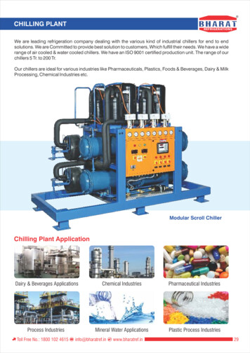
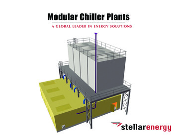
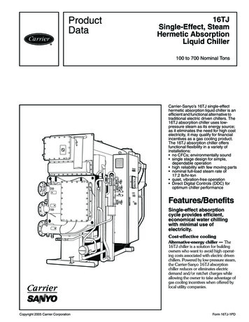
a30-4873WARNINGDO NOT USE TORCH to remove any component. Systemcontains oil and refrigerant under pressure.To remove a component, wear protective gloves and goggles and proceed as follows:a. Shut off electrical power to unit.b. Recover refrigerant to relieve all pressure from system using both high-pressure and low pressure ports.c. Traces of vapor should be displaced with nitrogenand the work area should be well ventilated. Refrigerant in contact with an open flame produces toxicgases.d. Cut component connection tubing with tubing cutterand remove component from unit. Use a pan to catchany oil that may come out of the lines and as a gagefor how much oil to add to the system.e. Carefully unsweat remaining tubing stubs when necessary. Oil can ignite when exposed to torch flame.Failure to follow these procedures may result in personalinjury or death.3.5 ft (1.1 m)MINIMUM†6 ft(1.8 m)MINIMUM** Minimum for when coils face each other. Less clearance isrequired in other configurations.† Clearance of 3.5 ft is required when a coil faces the wall. Whenthere is no coil facing the wall, see the certified drawing for therequired service clearance.Fig. 2 — 30RAP010-060 Multiple Unit SeparationFor 30RAP070-150 units, see Fig. 3. When chillers are arranged in parallel, a minimum of 10 ft (3048 mm) betweenchillers is recommended. Acceptable clearance on the coolerconnection side or end opposite the control box of the unit canbe reduced to 3 ft (1 m) without sacrificing performance aslong as the remaining three sides are unrestricted. Acceptableclearance on the side with a control box can be reduced to 4 ft(1.3 m) due to NEC (National Electric Code) regulations, without sacrificing performance as long as the remaining threesides are unrestricted. Clearances between chillers in dualchiller applications may be reduced to 6 ft (1.8 m) without sacrificing performance provided the remaining sides are unrestricted. For acceptable clearance with layout involving morethan 2 chillers, please contact application engineering.CAUTIONDO NOT re-use compressor oil or any oil that has beenexposed to the atmosphere. Dispose of oil per local codesand regulations. DO NOT leave refrigerant system open toair any longer than the actual time required to service theequipment. Seal circuits being serviced and charge withdry nitrogen to prevent oil contamination when timelyrepairs cannot be completed. Failure to follow these procedures may result in damage to equipment.6 ft (1.8 m)MINIMUMa30-490410 ft(3 m)MINIMUMINSTALLATIONStorage — If the unit is to be stored for a period of timebefore installation or start-up, be sure to protect the machinefrom construction dirt. Keep protective shipping covers inplace until the machine is ready for installation.Fig. 3 — 30RAP070-150 Multiple Unit SeparationThese instructions cover installation of 30RAP010-150 aircooled liquid chillers. Refer to Fig. 4 for model number to determine factory-installed options.RIGGING — Preferred method for rigging is with spreaderbars from above the unit. Use shackles in lifting holes. Rig at asingle point with 4 cables for size 010-115 units, 6 cables forsize 130 and 150 units, or use spread bars. All panels must bein place when rigging. See rigging label on unit for details concerning shipping weights, distance between lifting holes, centerof gravity, and lifting ring dimensions. See Tables 1-3 andFig. 5 for unit weights. See Tables 4 and 5 for physical data. See Fig. 6 and 7 for rigging label.If overhead rigging is not possible, place chiller on skid orpad for rolling or dragging. When rolling, use a minimum of3 rollers. When dragging, pull the pad. Do not apply force tothe unit. When in final position, raise from above to lift unitoff pad.Step 1 — Place and Rig the UnitPLACING UNIT — Units are suitable for outdoor use only.For 30RAP010-060 units, see Fig. 2. When parallel chillers arealigned such that coils face each other, a minimum of 6 ft(1829 mm) separation is recommended. When the parallel arrangement has only one coil drawing air from the space between chillers, a minimum of 3.5 ft (1067 mm) is recommended. When parallel chillers have no coils facing each other (aback-to-back arrangement), be sure to maintain the larger ofthe recommended service clearances associated with eachchiller (see the certified drawings). Due to NEC (NationalElectric Code, U.S.A.) regulations, a minimum clearance of4 ft (1219 mm) must be maintained on the side of the chillerthat has an electrical box. Chiller fan discharge must be at leastas high as adjacent solid walls. Installation in pits is not recommended.CAUTIONAll panels must be in place when rigging. If they are not,damage to unit could result.2
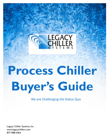
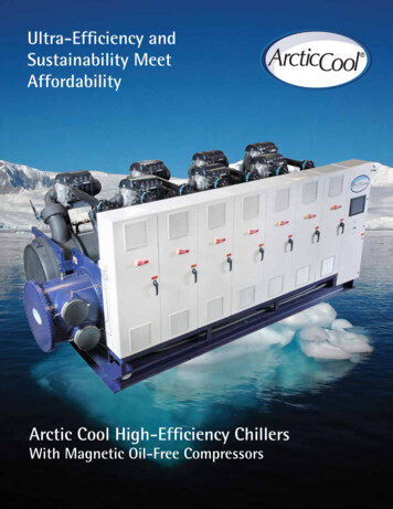
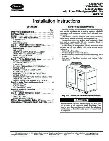
30RAP0106DB06Refrigerant TypeP – Puron 0Controls/Communications Options0 – Std1 – Std, BACnet Communication5 – EMM6 – EMM, BACnet CommunicationB – EMM, GFIC – EMM, GFI, BACnet CommunicationH – GFIJ – GFI, BACnet Communication070 115080 130090 150100Voltage1 – 575-3-602 – 380-3-605 – 208/230-3-606 – 460-3-609 – 380/415-3-50Electrical Options30RAP010-0600 – No Disconnect, No Cooler Heater1 – No Disconnect, Cooler HeaterD – Non-Fused Disconnect, No Cooler HeaterF – Non-Fused Disconnect, Cooler HeaterCondenser Coil and Low Sound Options0 – Aluminum/Copper, Value Sound Fan1 – Copper/Copper, Value Sound Fan2 – Aluminum/Copper, Pre-Coat, Value Sound Fan3 – Aluminum/Copper, E-Coat, Value Sound Fan4 – Copper/Copper, E-Coat, Value Sound Fan5 – MCHX, Value Sound Fan6 – MCHX, E-Coat, Value Sound Fan7 – Aluminum/Copper, AeroAcoustic Fan8 – Copper/Copper, AeroAcoustic Fan9 – Copper/Aluminum, Pre-Coat, AeroAcoustic FanB – Copper/Aluminum, E-Coat, AeroAcoustic FanC – Copper/Copper, E-Coat, AeroAcoustic FanD – MCHX, AeroAcoustic FanF – MCHX, E-Coat, AeroAcoustic FanJ – MCHX, AeroAcoustic Fan, Compressor Blanket(s)K – MCHX, E-Coat, AeroAcoustic Fan, Compressor Blanket(s)L – Aluminum/Copper, AeroAcoustic Fan, Compressor Blanket(s)M – Copper/Copper, AeroAcoustic Fan, Compressor Blanket(s)N – Aluminum/Copper, Pre-Coat, AeroAcoustic Fan, Compressor Blanket(s)P – Aluminum/Copper, E-Coat, AeroAcoustic Fan, Compressor Blanket(s)Q – Copper/Copper, E-Coat, AeroAcoustic Fan, Compressor Blanket(s)30RAP070-1500 – Single Point, No Disconnect, No Cooler Heater1 – Single Point, No Disconnect, Cooler Heater2 – Single Point, Non-Fused Disconnect, No Cooler Heater3 – Single Point, Non-Fused Disconnect, Cooler Heater4 – Dual Point, No Disconnect, No Cooler Heater5 – Dual Point, No Disconnect, Cooler HeaterAmbient/Capacity Control/High SCCR Options0 – Std Comp1 – Hot Gas Bypass2 – Digital Comp3 – Std Comp, High SCCR4 – Hot Gas Bypass, High SCCR5 – Digital Comp, High SCCR6 – Low Ambient, Std Comp7 – Low Ambient, Hot Gas Bypass8 – Low Ambient, Digital Comp9 – Low Ambient, Std Comp, High SCCRB – Low Ambient, Hot Gas Bypass, High SCCRC – Low Ambient, Digital Comp, High SCCRD – Std Comp, Suction Service ValveF – Hot Gas Bypass, Suction Service ValveG – Digital Comp, Suction Service ValveH – Std Comp, High SCCR, Suction Service ValveJ – Hot Gas Bypass, High SCCR, Suction Service ValveK – Digital Comp, High SCCR, Suction Service ValveL – Low Ambient, Std Comp, Suction Service ValvesM – Low Ambient, Hot Gas Bypass, Suction Service ValvesN – Low Ambient, Digital Comp, Suction Service ValvesP – Low Ambient, Std Comp, High SCCR, Suction Service ValvesQ – Low Ambient, Hot Gas Bypass, High SCCR, Suction Service ValvesR – Low Ambient, Digital Comp, High SCCR, Suction Service ValvesRevision LevelB – Current Revision LevelHydronic System30RAP010-0600 – No Pump2 – Single Pump, 1.5 Hp3 – Single Pump, 3 Hp4 – Single Pump, 3 Hp High Head5 – Single Pump, 5 Hp6 – Single Pump, 5 Hp High Head7 – Single Pump, 7.5 HpZ – Single Pump, 10 Hp9 – Dual Pump, 1.5 HpB – Dual Pump, 3 HpC – Dual Pump, 3 Hp High HeadD – Dual Pump, 5 HpF – Dual Pump, 5 Hp High HeadG – Dual Pump, 7.5 HpH – Dual Pump, 10 Hp0Packaging/Security Options0 – Std Packaging4 – Security Grilles/Hail Guards Only8 – Skid OnlyD – Skid, Security Grilles/Hail GuardsJ – Skid, Top Crate, BagN – Skid, Top Crate, Bag, Security Grilles/Hail Guards30RA – Air-Cooled AquaSnap ChillerUnit Sizes010 025 045015 030 050018 035 055020 040 060030RAP070-1500 – No Pump1 – Single Pump, 3 Hp2 – Single Pump, 5 Hp3 – Single Pump, 7.5 Hp4 – Single Pump, 10 Hp5 – Single Pump, 15 Hp6 – Dual Pump, 3 Hp7 – Dual Pump, 5 Hp8 – Dual Pump, 7.5 Hp9 – Dual Pump, 10 HpB – Dual Pump, 15 HpC – Single Pump, 3 Hp with VFDD – Single Pump, 5 Hp with VFDF – Single Pump, 7.5 Hp with VFDG – Single Pump, 10 Hp with VFDH – Single Pump, 15 Hp with VFDJ – Dual Pump, 3 Hp with VFDK – Dual Pump, 5 Hp with VFDL – Dual Pump, 7.5 Hp with VFDM – Dual Pump, 10 Hp with VFDN – Dual Pump, 15 Hp with VFDa30-5718LEGENDEMM —GFI—MCHX —VFD —Energy Management ModuleGround Fault InterruptingMicrochannel Heat ExchangerVariable Frequency DriveFig. 4 — AquaSnap Chiller Model Number Designation3
Table 1 — MCHX Unit Operating WeightsMCHX STANDARD UNITSWEIGHT AT MOUNTING POINTS 90500864516938WEIGHT AT MOUNTING POINTS 6107510771547165216772127227229263147MCHX SINGLE PUMP UNITSWEIGHT AT MOUNTING POINTS 0615089540768507337WEIGHT AT MOUNTING POINTS 11711182123112331729183018422308245331073328MCHX DUAL PUMP UNITSWEIGHT AT MOUNTING POINTS 630624092439044115374569271357622NOTE: See Fig. 5 for unit mounting points.4WEIGHT AT MOUNTING POINTS 30313271338138613891856199120012438258232363457
Table 2 — RTPF Unit Operating Weights (Al/Cu Coil)AL/CU COIL NO PUMP UNITSWEIGHT AT MOUNTING POINTS 406441195548593971137673WEIGHT AT MOUNTING POINTS 63480AL/CU COIL SINGLE PUMP UNITSWEIGHT AT MOUNTING POINTS ght4161445744835947633875128072WEIGHT AT MOUNTING POINTS 73661AL/CU COIL DUAL PUMP UNITS30RAPSIZE070080090100115130150AL/CUWEIGHT AT MOUNTING POINTS (lb)ABCD1201 1216 1018 10051237 1282 1128 10891197 1333 1177 10571459 1023 10341091483 1055 1113 11801744 1383 1565 10051771 1421 1706 1112LEGEND— Aluminum Fin/Copper 070080090100115130150WEIGHT AT MOUNTING POINTS (kg)ABCDE545552 462456——561581 512494—543605 534479282662464 469495321673478 505535291791627 710456340803645 774504NOTE: See Fig. 5 for unit mounting 1602827300435363790
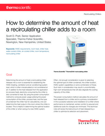
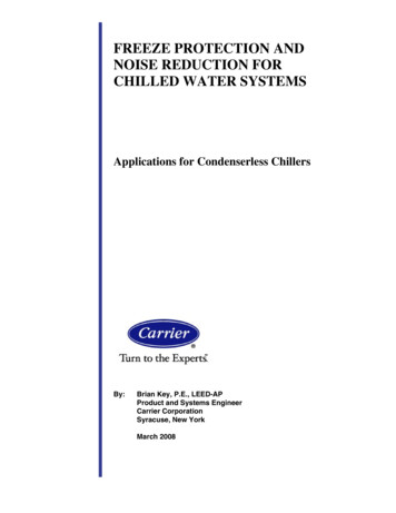
Table 3 — RTPF Unit Operating Weights (Cu/Cu Coil)CU/CU COIL NO PUMP UNITSWEIGHT AT MOUNTING POINTS ight4359478448396388689981938873WEIGHT AT MOUNTING POINTS 64025CU/CU COIL SINGLE PUMP UNITSWEIGHT AT MOUNTING POINTS 80090100115130150WEIGHT AT MOUNTING POINTS 0234823603078331038974206CU/CU COIL DUAL PUMP UNITS30RAPSIZE070080090100115130150CU/CUWEIGHT AT MOUNTING POINTS (lb)ABCD1364 1381 1156 11411425 1476 1300 12551378 1534 1355 12161558 1134 1246 11871597 1181 1356 12911875 1523 1834 11371917 1575 2004 1260LEGEND— Copper Fin/Copper 99a30-4861WEIGHT AT MOUNTING POINTS 0RAP100-150UNITSE618626 524518——647670 590569—625696 614552333707514 565539379724536 615586353851691 832516150870715 909571406NOTE: See Fig. 5 for unit mounting 545754837072758388779557CONTROLBOXSIDEAFFig. 5 — Unit Mounting Points6E
Table 4 — Physical Data, 30RAP — EnglishUNIT 30RAPOPERATING WEIGHT (lb)MCHX Condenser Coil, No PumpMCHX Condenser Coil, Single Pump(60 Hz only)MCHX Condenser Coil, Dual Pump(60 Hz only)REFRIGERANT TYPETotal Refrigerant Charge (lb)Refrigerant Charge (lb) Ckt A/Ckt BCOMPRESSORSQuantitySpeed (Rpm)(Qty) Tons, Ckt A(Qty) Tons, Ckt BOil Charge (Pt) Ckt A/Ckt BNo. Capacity StepsStandardWith Hot Gas BypassDigital Compressor OptionMinimum Capacity Step (%)StandardWith Hot Gas BypassDigital Compressor OptionCapacity (%)Circuit ACircuit BCOOLERWeight (lb) (empty)Net Fluid Volume (gal)Maximum Refrigerant Pressure (psig)Maximum Water-Side PressureWithout Pump(s) (psig)Maximum Water-Side PressureWith Pump(s) (psig)CHILLER WATER CONNECTIONS (in.)Inlet and Outlet, Victaulic(IPS Carbon Steel)*Drain (NPT)CONDENSER FANSStandard Low-Sound AeroAcoustic TypeFan Speed (Rpm)No. Blades.Diameter (in.)No. FansTotal Airflow 60 Hz (Cfm)Total Airflow 50 Hz (Cfm)Optional Value Sound TypeFan Speed (Rpm)No. Blades.Diameter (in.)No. FansTotal Airflow 60 Hz (Cfm)Total Airflow 50 Hz (Cfm)CONDENSER COILSQuantity (Ckt A/Ckt B)Total Face Area (sq ft)Maximum Refrigerant Pressure (psig)HYDRONIC MODULE (Optional)†PumpExpansion Tank Volume (gal)Total/AcceptanceCHASSIS DIMENSIONS (ft - 7/17.0444(2) 10(2) 1113.8/13.8(2) 11(2) 1313.8/13.8(2) 13(2) 1313.8/13.8R-410A, EXV Controlled /14.9Scroll, Hermetic22243500 (60 Hz)/2900 (50 Hz)(2) 10(2) 13(2) 15(2) 10———(2) /—14.614.6/—112(1) 11—6.9/—(1) 15—6.9/—(2) 15015015015015015010010010054———46Brazed, Direct-Expansion Plate Heat Plastic Type, Axial, Vertical Discharge850 (60 Hz)/710 (50 ,71624,71625,46825,468Propeller Type, Axial, Vertical Discharge1140 (60 Hz)/950 (50 026,72027,80527,805Novation MCHX Aluminum Tube, Aluminum s), Strainer with Blowdown Valve, Expansion Tank, Pressure Taps, Drain and Vent Plugs, Flow Switch, and BalanceValveSingle or Dual, Centrifugal Monocell Pump(s), 3500 Rpm. Dual pumps with check valves and isolation -6LEGENDEXV—MCHX -57-96-6*Unit connection is IPS Carbon Steel piping.†Flow switch and strainer are standard on all units, with or without hydronicpackage.Electronic Expansion ValveMicrochannel Heat Exchanger7
Table 4 — Physical Data, 30RAP — English (cont)UNIT 30RAPOPERATING WEIGHT (lb)MCHX Condenser Coil, No PumpMCHX Condenser Coil, Single Pump (60 Hz only)MCHX Condenser Coil, Dual Pump (60 Hz only)Al-Cu Condenser Coil, No PumpAl-Cu Condenser Coil, Single Pump (60 Hz only)Al-Cu Condenser Coil, Dual Pump (60 Hz only)Cu-Cu Condenser Coil, No PumpCu-Cu Condenser Coil, Single Pump (60 Hz only)Cu-Cu Condenser Coil, Dual Pump (60 Hz only)REFRIGERANT TYPETotal Refrigerant Charge MCHX (lb)Refrigerant Charge MCHX (lb) Ckt A/Ckt BTotal Refrigerant Charge RTPF (lb)Refrigerant Charge RTPF (lb) Ckt A/Ckt BCOMPRESSORSQuantitySpeed (Rpm)(Qty, Tons) Ckt A(Qty, Tons) Ckt BOil Charge (Pt) Ckt A/Ckt BNo. Capacity StepsStandardWith Hot Gas BypassDigital Compressor OptionMinimum Capacity Step (%)StandardWith Hot Gas BypassDigital Compressor OptionCapacity (%)Circuit ACircuit BCOOLERWeight (lb) (empty)Net Fluid Volume (gal)Maximum Refrigerant Pressure (psig)Maximum Water-Side PressureWithout Pump(s) (psig)Maximum Water-Side PressureWith Pump(s) (psig)CHILLER WATER CONNECTIONS (in.)Inlet and Outlet, Victaulic(IPS Carbon Steel)*Drain (NPT)CONDENSER FANSStandard Low-Sound AeroAcoustic TypeFan Speed (Rpm)No. Blades.Diameter (in.)No. FansTotal Airflow (Cfm), 60 HzTotal Airflow (Cfm), 50 HzOptional Value Sound TypeFan Speed (Rpm)No. Blades.Diameter (in.)No. FansTotal Airflow (Cfm), 60 HzTotal Airflow (Cfm), 50 HzCONDENSER COILSQuantity (Ckt A/Ckt B)Total Face Area (sq ft)Maximum Refrigerant Pressure (psig)HYDRONIC MODULE (Optional, 60 Hz Only)†PumpExpansion Tank Volume (gal)Total/AcceptanceCHASSIS DIMENSIONS (ft - .0132.0/132.0445666(2) 13(2) 1513.8/13.8(2) 15(2) 1513.8/13.8(2) 15(3) 1513.8/20.6(3) 20(3) 2042.6/42.6(3) 20(3) 2542.6/42.6(3) 25(3) croll, Hermetic653500 (60 Hz)/ 2900 (50Hz)(3) 13(3) 15(1) 20 (1) 25(3) 15(3) 15(3) 2020.6/20.620.6/20.628.4/42.66Brazed, Direct-Expansion Plate Heat Exchanger2282452675.06.87.4450450450222Plastic Type, Axial, Vertical ,80032,3984.30441,80034,903Novation MCHX Aluminum Tube, Aluminum 614850 (60 Hz)/710 (50 42,809Propeller Type, Axial, Vertical Discharge1140 (60 Hz)/950 (50 6Novation MCHX Aluminum Tube, Aluminum Fin or RTPF3/3149.66563/4174.56564/4199.4656Pump(s), Strainer with Blowdown Valve, Expansion Tank, Pressure Taps, Drain and Vent Plugs, Flow Switch, and Balance ValveSingle or Dual, Centrifugal Monocell Pump(s), 3500 Rpm. Dual pumps with check valves and isolation , EXV Controlled 170.0192.084.6/84.685.0/85.087.0/105.0Electronic Expansion ValveMicrochannel Heat ExchangerRound Tube, Plate Fin (Condenser Coil)*Unit connection is IPS Carbon Steel piping.†Flow switch and strainer are standard on all units, with or without hydronic package.8
Table 5 — Physical Data, 30RAP — SIUNIT 30RAPOPERATING WEIGHT (kg)MCHX Condenser Coil, No PumpMCHX Condenser Coil, Single Pump(60 Hz only)MCHX Condenser Coil, Dual Pump(60 Hz only)REFRIGERANT TYPETotal Refrigerant Charge (kg)Refrigerant Charge (kg) Ckt A/Ckt BCOMPRESSORSQuantitySpeed (R/s)(Qty) kW, Ckt A(Qty) kW, Ckt BOil Charge (L) Ckt A/Ckt BNo. Capacity StepsStandardWith Hot Gas BypassDigital Compressor OptionMinimum Capacity Step (%)StandardWith Hot Gas BypassDigital Compressor OptionCapacity (%)Circuit ACircuit BCOOLERWeight (kg) (empty)Net Fluid Volume (L)Maximum Refrigerant Pressure (kPa)Maximum Water-Side PressureWithout Pump(s) (kPa)Maximum Water-Side PressureWith Pump(s) (kPa)CHILLER WATER CONNECTIONS (in.)Inlet and Outlet, Victaulic(IPS Carbon Steel)*Drain (NPT)CONDENSER FANSStandard Low-Sound AeroAcoustic TypeFan Speed (R/s)No. Blades.Diameter (mm)No. FansTotal Airflow 60 Hz (L/s)Total Airflow 50 Hz (L/s)Optional Value Sound TypeFan Speed (R/s)No. Blades.Diameter (mm)No. FansTotal Airflow 60 Hz (L/s)Total Airflow 50 Hz (L/s)CONDENSER COILSQuantity (Ckt A/Ckt B)Total Face Area (sq m)Maximum Refrigerant Pressure (kPa)HYDRONIC MODULE (Optional)†PumpExpansion Tank Volume (L)Total/AcceptanceCHASSIS DIMENSIONS 44(2) 35(2) 326.5/6.5(2) 35(2) 386.5/6.5(2) 38(2) 466.5/6.5(2) 46(2) 122(1) 38—3.3/—(1) 53—3.3/—(2) 32—6.5/—(2) Brazed, Direct-Expansion Plate Heat 0341034103410341034Scroll, Hermetic2258.3 (60 Hz)/48.3 (50 Hz)(2) 46(2) 1/1/1/1/1/1/1/4444444444Plastic Type, Axial, Vertical 74.7621476739814.7621476739814.76228732729114.2 (60 Hz)/11.8 (50 Hz)9.7629.7629.7629.762222382609157915713 97168977646764611 666Propeller Type, Axial, Vertical Discharge19.0 (60 Hz)/15.8 (50 Hz)4.7624.7624.7624.762222387329865986515 10472918237823712 6121/—1.645231/—1.645231/—2.44523Novation MCHX Aluminum Tube, Aluminum .762313 97111 6669.762314 39612 0219.762314 39612 0214.762315 10412 6124.762315 71813 1244.762315 71813 1241/14.945231/16.145231/16.14523Pump(s), Strainer with Blowdown Valve, Expansion Tank, Pressure Taps, Drain and Vent Plugs, Flow Switch, and Balance ValveSingle or Dual, Centrifugal Monocell Pump(s), 3500 Rpm. Dual pumps with check valves and isolation 8939.0/39.0224210251689LEGENDEXVMCHXR-410A, EXV Controlled 4*Unit connection is IPS Carbon Steel piping.†Flow switch and strainer are standard on all units, with or without hydronic package.Electronic Expansion ValveMicrochannel Heat Exchanger9
Table 5 — Physical Data, 30RAP — SI (cont)UNIT 30RAPOPERATING WEIGHT (kg)MCHX Condenser Coil, No PumpMCHX Condenser Coil, Single Pump (60 Hz only)MCHX Condenser Coil, Dual Pump (60 Hz only)Al-Cu Condenser Coil, No PumpAl-Cu Condenser Coil, Single Pump (60 Hz only)Al-Cu Condenser Coil, Dual Pump (60 Hz only)Cu-Cu Condenser Coil, No PumpCu-Cu Condenser Coil, Single Pump (60 Hz only)Cu-Cu Condenser Coil, Dual Pump (60 Hz only)REFRIGERANT TYPETotal Refrigerant Charge MCHX (kg)Refrigerant Charge MCHX (kg) Ckt A/Ckt BTotal Refrigerant Charge RTPF (kg)Refrigerant Charge RTPF (kg) Ckt A/Ckt BCOMPRESSORSQuantitySpeed (R/s)(Qty, kW) Ckt A(Qty, kW) Ckt BOil Charge (L) Ckt A/Ckt BNo. Capacity StepsStandardWith Hot Gas BypassDigital Compressor OptionMinimum Capacity Step (%)StandardWith Hot Gas BypassDigital Compressor OptionCapacity (%)Circuit ACircuit BCOOLERWeight (kg) (empty)Net Fluid Volume (L)Maximum Refrigerant Pressure (kPa)Maximum Water-Side PressureWithout Pump(s) (kPa)Maximum Water-Side PressureWith Pump(s) (kPa)CHILLER WATER CONNECTIONS (in.)Inlet and Outlet, Victaulic(IPS Carbon Steel)*Drain (NPT)CONDENSER FANSStandard Low-Sound AeroAcoustic TypeFan
clearance on the side with a control box can be reduced to 4 ft (1.3 m) due to NEC (National Electric Code) regulations, with-out sacrificing performance as long as the remaining three . 5 - EMM 6 - EMM, BACnet Communication B - EMM, GFI C - EMM, GFI, BACnet Communication H - GFI J - GFI, BACnet Communication Packaging/Security .