Transcription
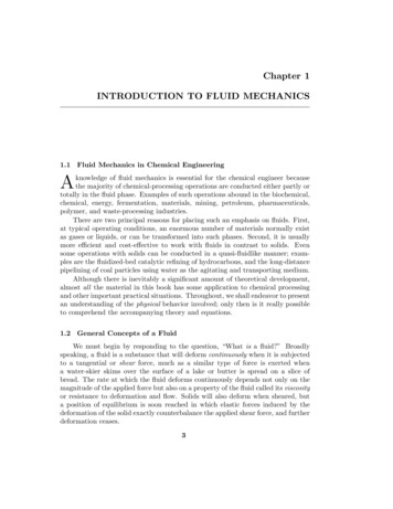
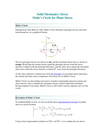
Solid Mechanics: StressMohr's Circle for Plane StressMohr's CircleIntroduced by Otto Mohr in 1882, Mohr's Circle illustrates principal stresses and stresstransformations via a graphical format,The two principal stresses are shown in red, and the maximum shear stress is shown inorange. Recall that the normal stesses equal the principal stresses when the stresselement is aligned with the principal directions, and the shear stress equals the maximumshear stress when the stress element is rotated 45 away from the principal directions.As the stress element is rotated away from the principal (or maximum shear) directions,the normal and shear stress components will always lie on Mohr's Circle.Mohr's Circle was the leading tool used to visualize relationships between normal andshear stresses, and to estimate the maximum stresses, before hand-held calculatorsbecame popular. Even today, Mohr's Circle is still widely used by engineers all over theworld.Derivation of Mohr's CircleTo establish Mohr's Circle, we first recall the stress transformation formulas for planestress at a given location,Using a basic trigonometric relation (cos22θ sin22θ 1) to combine the two above
equations we have,This is the equation of a circle, plotted on a graph where the abscissa is the normal stressand the ordinate is the shear stress. This is easier to see if we interpret σx and σy as beingthe two principal stresses, and τxy as being the maximum shear stress. Then we can definethe average stress, σavg, and a "radius" R (which is just equal to the maximum shearstress),The circle equation above now takes on a more familiar form,The circle is centered at the average stress value, and has a radius R equal to themaximum shear stress, as shown in the figure below,Related TopicsThe procedure of drawing a Mohr's Circle from a given stress state is discussed in theMohr's Circle usage page.The Mohr's Circle for plane strain can also be obtained from similar procedures.
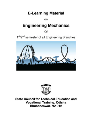
Solid Mechanics: StressPlane Stress and Coordinate TransformationsPlane State of StressA class of common engineering problemsinvolving stresses in a thin plate or on the freesurface of a structural element, such as thesurfaces of thin-walled pressure vessels underexternal or internal pressure, the free surfacesof shafts in torsion and beams under transverseload, have one principal stress that is muchsmaller than the other two. By assuming thatthis small principal stress is zero, the threedimensional stress state can be reduced to twodimensions. Since the remaining two principalstresses lie in a plane, these simplified 2Dproblems are called plane stress problems.Assume that the negligible principal stress isoriented in the z-direction. To reduce the 3Dstress matrix to the 2D plane stress matrix, remove all components with z subscripts toget,where τxy τyx for static equilibrium. The sign convention for positive stress componentsin plane stress is illustrated in the above figure on the 2D element.Coordinate TransformationsThe coordinate directions chosen to analyze a structure are usually based on the shape ofthe structure. As a result, the direct and shear stress components are associated with thesedirections. For example, to analyze a bar one almost always directs one of the coordinatedirections along the bar's axis.Nonetheless, stresses in directions that do not line up with the original coordinate set arealso important. For example, the failure plane of a brittle shaft under torsion is often at a45 angle with respect to the shaft's axis. Stress transformation formulas are required to
analyze these stresses.The transformation of stresses with respect to the {x,y,z} coordinates to the stresses withrespect to {x',y',z'} is performed via the equations,where θ is the rotation angle between the two coordinate sets (positive in thecounterclockwise direction). This angle along with the stresses for the {x',y',z'}coordinates are shown in the figure below,
Solid Mechanics: StressPrincipal Stress for the Case of Plane StressPrincipal Directions, Principal StressThe normal stresses (σx' and σy') and the shear stress (τx'y') vary smoothly with respect tothe rotation angle θ, in accordance with the coordinate transformation equations. Thereexist a couple of particular angles where the stresses take on special values.First, there exists an angle θp where the shear stress τx'y' becomes zero. That angle isfound by setting τx'y' to zero in the above shear transformation equation and solving for θ(set equal to θp). The result is,The angle θp defines the principal directions where the only stresses are normal stresses.These stresses are called principal stresses and are found from the original stresses(expressed in the x,y,z directions) via,The transformation to the principal directions can be illustrated as:
Maximum Shear Stress DirectionAnother important angle, θs, is where the maximum shear stress occurs. This is found byfinding the maximum of the shear stress transformation equation, and solving for θ. Theresult is,The maximum shear stress is equal to one-half the difference between the two principalstresses,The transformation to the maximum shear stress direction can be illustrated as:
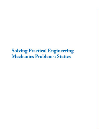
Solid Mechanics: StressMohr's Circle Usage in Plane StressPrincipal Stresses from Mohr's CircleA chief benefit of Mohr's circle is that the principalstresses σ1 and σ2 and the maximum shear stress τmax areobtained immediately after drawing the circle,where,Principal Directions from Mohr's CircleMohr's Circle can be used to find the directions of the principal axes. To show this, firstsuppose that the normal and shear stresses, σx, σy, and τxy, are obtained at a given point Oin the body. They are expressed relative to the coordinates XY, as shown in the stresselement at right below.The Mohr's Circle for this general stress state is shown at left above. Note that it'scentered at σavg and has a radius R, and that the two points {σx, τxy} and {σy, -τxy} lie onopposites sides of the circle. The line connecting σx and σy will be defined as Lxy.The angle between the current axes (X and Y) and the principal axes is defined as θp, and
is equal to one half the angle between the line Lxy and the σ-axis as shown in theschematic below,A set of six Mohr's Circles representing most stress state possibilities are presented on theexamples page.Rotation Angle on Mohr's CircleNote that the coordinate rotation angle θp is defined positive when starting at the XYcoordinates and proceeding to the XpYp coordinates. In contrast, on the Mohr's Circle θp isdefined positive starting on the principal stress line (i.e. the σ-axis) and proceeding to theXY stress line (i.e. line Lxy). The angle θp has the opposite sense between the two figures,because on one it starts on the XY coordinates, and on the other it starts on the principalcoordinates.Some books avoid this dichotomy between θp on Mohr's Circle and θp on the stresselement by locating (σx, -τxy) instead of (σx, τxy) on Mohr's Circle. This will switch thepolarity of θp on the circle. Whatever method you choose, the bottom line is that anopposite sign is needed either in the interpretation or in the plotting to make Mohr'sCircle physically meaningful.Stress Transform by Mohr's CircleMohr's Circle can be used to transform stresses from one coordinate set to another,similar that that described on the plane stress page.Suppose that the normal and shear stresses, σx, σy, and τxy, are obtained at a point O in the
body, expressed with respect to the coordinates XY. We wish to find the stressesexpressed in the new coordinate set X'Y', rotated an angle θ from XY, as shown below:To do this we proceed as follows: Draw Mohr's circle for the given stress state (σx, σy, and τxy; shown below). Draw the line Lxy across the circle from (σx, τxy) to (σy, -τxy). Rotate the line Lxy by 2*θ (twice as much as the angle between XY and X'Y') and in theopposite direction of θ. The stresses in the new coordinates (σx', σy', and τx'y') are then read off the circle.
Solid Mechanics: StrainMohr's Circle for Plane StrainMohr's CircleStrains at a point in the body can be illustrated by Mohr's Circle. The idea and proceduresare exactly the same as for Mohr's Circle for plane stress.The two principal strains are shown in red, and the maximum shear strain is shown inorange. Recall that the normal strains are equal to the principal strains when the elementis aligned with the principal directions, and the shear strain is equal to the maximumshear strain when the element is rotated 45 away from the principal directions.As the element is rotated away from the principal (or maximum strain) directions, thenormal and shear strain components will always lie on Mohr's Circle.Derivation of Mohr's CircleTo establish the Mohr's circle, we first recall the strain transformation formulas for planestrain,Using a basic trigonometric relation (cos22θ sin22θ 1) to combine the above twoformulas we have,
This equation is an equation for a circle. To make this more apparent, we can rewrite itas,where,The circle is centered at the average strain value εAvg, and has a radius R equal to themaximum shear strain, as shown in the figure below,Related TopicsThe procedure of drawing Mohr's Circle from a given strain state is discussed in theMohr's Circle usage and examples pages.The Mohr's Circle for plane stress can also be obtained from similar procedures.
Solid Mechanics: StrainMohr's Circle Usage in Plane StrainPrincipal Strains from Mohr's CircleA chief benefit of Mohr's circle is that the principalstrains ε1 and ε2 and the maximum shear strain εxyMax areobtained immediately after drawing the circle,where,Principal Directions from Mohr's CircleMohr's Circle can be used to find the directions of the principal axes. To show this, firstsuppose that the normal and shear strains, εx, εy, and εxy, are obtained at a given point O inthe body. They are expressed relative to the coordinates XY, as shown in the strainelement at right below.The Mohr's Circle for this general strain state is shown at left above. Note that it'scentered at εAvg and has a radius R, and that the two points (εx, εxy) and (εy, -εxy) lie onopposites sides of the circle. The line connecting εx and εy will be defined as Lxy.The angle between the current axes (X and Y) and the principal axes is defined as θp, and
is equal to one half the angle between the line Lxy and the ε-axis as shown in theschematic below,A set of six Mohr's Circles representing most strain state possibilities are presented on theexamples page.Rotation Angle on Mohr's CircleNote that the coordinate rotation angle θp is defined positive when starting at the XYcoordinates and proceeding to the XpYp coordinates. In contrast, on the Mohr's Circle θp isdefined positive starting on the principal strain line (i.e. the ε-axis) and proceeding to theXY strain line (i.e. line Lxy). The angle θp has the opposite sense between the two figures,because on one it starts on the XY coordinates, and on the other it starts on the principalcoordinates.Some books avoid the sign difference between θp on Mohr's Circle and θp on the stresselement by locating (εx, -εxy) instead of (εx, εxy) on Mohr's Circle. This will switch thepolarity of θp on the circle. Whatever method you choose, the bottom line is that anopposite sign is needed either in the interpretation or in the plotting to make Mohr'sCircle physically meaningful.Strain Transform by Mohr's CircleMohr's Circle can be used to transform strains from one coordinate set to another, similarthat that described on the plane strain page.
Suppose that the normal and shear strains, εx, εy, and εxy, are obtained at a point O in thebody, expressed with respect to the coordinates XY. We wish to find the strains expressedin the new coordinate set X'Y', rotated an angle θ from XY, as shown below:To do this we proceed as follows: Draw Mohr's circle for the given strain state (εx, εy, and εxy; shown below). Draw the line Lxy across the circle from (εx, εxy) to (εy, -εxy). Rotate the line Lxy by 2*θ (twice as much as the angle between XY and X'Y') and in theopposite direction of θ. The strains in the new coordinates (εx', εy', and εx'y') are then read off the circle.
Solid Mechanics: StrainPlane Strain and Coordinate TransformationsPlane State of StrainSome common engineering problems such as adam subjected to water loading, a tunnel underexternal pressure, a pipe under internalpressure, and a cylindrical roller bearingcompressed by force in a diametral plane, havesignificant strain only in a plane; that is, thestrain in one direction is much less than thestrain in the two other orthogonal directions. Ifsmall enough, the smallest strain can beignored and the part is said to experienceplane strain.Assume that the negligible strain is oriented inthe z-direction. To reduce the 3D strain matrixto the 2D plane stress matrix, remove allcomponents with z subscripts to get,where εxy εyx by definition.The sign convention here is consistent with the sign convention used in plane stressanalysis.Coordinate TransformationThe transformation of strains with respect to the {x,y,z} coordinates to the strains withrespect to {x',y',z'} is performed via the equations,
The rotation between the two coordinate sets is shown here,where θ is defined positive in the counterclockwise direction.
Solid Mechanics: StrainPrincipal Strain for the Case of Plane StrainPrincipal Directions, Principal StrainThe normal strains (εx' and εy') and the shear strain (εx'y') vary smoothly with respect to therotation angle θ, in accordance with the transformation equations given above. Thereexist a couple of particular angles where the strains take on special values.First, there exists an angle θp where the shear strain εx'y' vanishes. That angle is given by,This angle defines the principal directions. The associated principal strains are given by,The transformation to the principal directions with their principal strains can beillustrated as:
Maximum Shear Strain DirectionAnother important angle, θs, is where the maximum shear strain occurs and is given by,The maximum shear strain is found to be one-half the difference between the twoprincipal strains,The transformation to the maximum shear strain direction can be illustrated as:
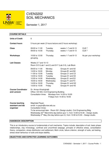
Solid Mechanics: StrainExamples of Mohr's Circles in Plane StrainCase 1: εxy 0 and εx εyThe principal axes are counterclockwise to the current axes (because εxy 0) and no morethan 45º away (because εx εy).Case 2: εxy 0 and εx εyThe principal axes are clockwise to the current axes (because εxy 0) and no more than45º away (because εx εy).Case 3: εxy 0 and εx εy
The principal axes are counterclockwise to the current axes (because εxy 0) and between45º and 90º away (because εx εy).Case 4: εxy 0 and εx εyThe principal axes are clockwise to the current axes (because εxy 0) and between 45ºand 90º away (because εx εy).Case 5: εxy 0 and εx εyThe principal axes are aligned with the current axes (because εx εy and εxy 0).
Case 6: εxy 0 and εx εyThe principal axes are exactly 90 from the current axes (because εx εy and εxy id Mechanics tress.htm
became popular. Even today, Mohr's Circle is still widely used by engineers all over the world. Derivation of Mohr's Circle To establish Mohr's Circle, we first recall the stress transformation formulas for plane stress at a given location, Using a basic trigonometric relation (cos22θ sin22θ 1) to combine the two above