Transcription
FRIEDRICH-ALEXANDER-UNIVERSITÄT ERLANGEN-NÜRNBERGINSTITUT FÜR INFORMATIK (MATHEMATISCHE MASCHINEN UND DATENVERARBEITUNG)Lehrstuhl für Informatik 10 (Systemsimulation)Numerical Simulation of Quenching Process in Coal GasificationRishi PatilMaster’s Thesis
Numerical Simulation of Quenching Process in Coal GasificationRishi PatilMaster’s ThesisAufgabensteller:Betreuer:Prof. Dr. U. RüdeA. HauserK. IglbergerDr. S. KosseBearbeitungszeitraum: 16.3.2009 – 16.9.2009
Erklärung:Ich versichere, dass ich die Arbeit ohne fremde Hilfe und ohne Benutzung anderer als derangegebenen Quellen angefertigt habe und dass die Arbeit in gleicher oder ähnlicher Formnoch keiner anderen Prüfungsbehörde vorgelegen hat und von dieser als Teil einer Prüfungsleistung angenommen wurde. Alle Ausführungen, die wörtlich oder sinngemäß übernommenwurden, sind als solche gekennzeichnet.Erlangen, den 16.09.2009.
AbstractThis Master’s Thesis compares two computational fluid dynamics solvers: the commercialsolver ANSYS CFX and the open source code OpenFOAM. Simple benchmark cases withcompressible and incompressible flows are tested and compared. Thereafter the more complexprocess of quenching in coal gasification is simulated.This thesis work describes the simulation of a part of the coal gasification process, namelythe water gas shift reaction or the quenching process. The quenching process involves simulation of a multicomponent, multiphase reactive flow system. This thesis uses the EulerianLagrangian approach to simulate the quenching process.It turns out that ANSYS CFX convinces in the first place with its robustness, especiallywhen dealing with steady state problem configurations. However OpenFOAM shows a muchbetter performance when dealing with strongly transient processes.ZusammenfassungDie vorliegende Masterarbeit vergleicht die Leistungsfähigkeit des kommerziellen CFDsolvers CFX und des open-source CFD-solvers OpenFOAM. Es wurden einerseits einfacheProblemstellungen kompressibler und inkompressibler Strömungen berechnet und evaluiert.Andererseits wurde der Quenching-Prozess, der einen wichtigen Teilprozess bei der Kohlevergasung darstellt, mit beiden Softwarepaketen simuliert und die Ergebnisse miteinanderverglichen. Das Modell zur Beschreibung des Quenching-Prozesses beinhaltet sowohl eineMehrkomponenten- als auch Mehrphasenströmung. Die Untersuchungen haben gezeigt, dassCFX vor allem durch die robusten Lösungseigenschaften überzeugt. Bei transienten Phänomenen allerdings, bei denen kleine Zeitschrittweiten verwendet werden mssen, ist OpenFOAMnicht zuletzt durch den semi-impliziten Ansatz deutlich schneller.
AcknowledgmentI would like to thank Prof. Dr. Ulrich Rüde for supporting the external thesis work atSiemens AG and for his guidance during the Master of Science Computational EngineeringProgram. I would also like to thank Klaus Iglberger for his assistance.I am thankful to Andreas Hauser and Dr. Sylvio Kosse for offering me the opportunityto pursue the thesis work at Siemens AG (Corporate Technology). The help of Dr. N. Huberand Dr. T. Hammer from Siemens Corporate Technology is greatfully acknowledged for thevaluable help related to the geometry and chemical kinetics.The developers of OpenFOAM are greatfully acknowledged for sharing their high qualitytool with the CFD community. I am thankful to the open source community (OpenFOAMforum on www.cfd-online.com) for answering my queries and giving me clues.Many friends made my studies and stay at Erlangen memorable. Amongst them I wouldlike to especially acknowledge Cherif, Ruchika and Sunil. I would not have been able to studyat Erlangen without the care, support and motivation from my parents and sister.
Contents1 Introduction22 Fundamentals of Coal Gasification2.1 Introduction to Coal Gasification . . . . . . . . . . . . . . . . . . . . . . . . . .2.2 Quenching Process . . . . . . . . . . . . . . . . . . . . . . . . . . . . . . . . . .4483 Modeling of Quenching Process in Coal Gasification103.1 Physical Processes . . . . . . . . . . . . . . . . . . . . . . . . . . . . . . . . . . 103.2 Mathematical Formulation : Eulerian Phase . . . . . . . . . . . . . . . . . . . . 113.3 Mathematical Formulation : Lagrangian Phase . . . . . . . . . . . . . . . . . . 134 Numerics and Comparison of Solvers4.1 Physical Models: Turbulence, Multiphase and4.2 Discretization Methods . . . . . . . . . . . . .4.3 Solution Algorithms . . . . . . . . . . . . . .4.4 Parallelization . . . . . . . . . . . . . . . . . .4.5 Mesh Import and Conversion . . . . . . . . .4.6 Materials Library and Chemistry . . . . . . .Radiation. . . . . . . . . . . . . . . . . . . . . . . . . .161617182021235 Numerical Results245.1 Benchmark Reactor . . . . . . . . . . . . . . . . . . . . . . . . . . . . . . . . . 245.2 Benchmark T-Junction . . . . . . . . . . . . . . . . . . . . . . . . . . . . . . . . 255.3 Quencher . . . . . . . . . . . . . . . . . . . . . . . . . . . . . . . . . . . . . . . 286 Summary and Outlook31A Codes for incompressible mixing fluid solvers33A.1 createFields.H . . . . . . . . . . . . . . . . . . . . . . . . . . . . . . . . . . . . . 33A.2 myInkIcoFoam.C . . . . . . . . . . . . . . . . . . . . . . . . . . . . . . . . . . . 35A.3 myInkSimpleFoam.C . . . . . . . . . . . . . . . . . . . . . . . . . . . . . . . . . 37B dieselFoam solver39B.1 sprayProperties . . . . . . . . . . . . . . . . . . . . . . . . . . . . . . . . . . . . 39B.2 injectorProperties . . . . . . . . . . . . . . . . . . . . . . . . . . . . . . . . . . . 42C CHEMKIN file format44
List of Figures2.12.22.32.42.52.6Simple Steam Cycle [24] . . . . . . . . . . .Gas turbine with open cycle [24] . . . . . .Gas turbine with combined cycle [24] . . . .Block flow diagram of an IGCC power plantSiemens Coal Gasification [21] . . . . . . . .Siemens Quencher [24] . . . . . . . . . . . .6677894.1General field solution process used in the CFX-Solver [7] . . . . . . . . . . . . Cross section of the reactor . . . . . . . . . . . . . . .Temperature vs flow rate . . . . . . . . . . . . . . . .Temperature profile of cross-section with OpenFOAMTemperature profile of cross-section with ANSYS CFXSpeedup of OpenFOAM vs CFX . . . . . . . . . . . .CFX Re 100 . . . . . . . . . . . . . . . . . . . . . . .OpenFOAM Re 100 . . . . . . . . . . . . . . . . . . .CFX Re 1000 . . . . . . . . . . . . . . . . . . . . . .OpenFOAM Re 1000 . . . . . . . . . . . . . . . . . .CFX Re 10,000 . . . . . . . . . . . . . . . . . . . . .OpenFOAM Re 10,000 . . . . . . . . . . . . . . . . .Mixing of the tracer along the length of pipes . . . . .Temperature profile at central plane (CFX) . . . . . .Temperature profile at central plane (OpenFOAM) . .2525262627272728282828283030iii. . . . . . .[24]. . . . .
TrademarksANSYS is a registered trademark of ANSYS Inc.CFX is a registered trademark of ANSYS Inc.CHEMKIN is a registered trademark of Reaction Design Corporation.Fluent is a registered trademark of ANSYS Inc.Icem-CFD is a registered trademark of ANSYS Inc.Linux is a registered trademark of Linus Torvalds.OpenFOAM is a registered trademark of OpenCFD Ltd.ParaView is a registered trademark of Kitware.Star-CCM is a registered trademark of CD-Adapco.
Chapter 1IntroductionIn recent years, numerical simulations have become an indispensable tool for research and development activities. The classical approach of experimentally determining the performanceof a system has several disadvantages especially with respect to cost, time and parameter variations. In addition, the decreasing cost of computers has made it possible to assemble a highperformance computing cluster from off the shelf computer components. Computational FluidDynamics (CFD) has become an essential part of research involving fluids. CFD can be usedas a tool in wide range of applications, from simple hydrodynamic flow to multicomponent,multiphase reacting flows.There are various CFD tools available in the market. ANSYS Inc. is one of the largestcompanies involved in numerical simulation. Two main ANSYS fluid dynamics solvers areANSYS CFX and ANSYS Fluent. The other major CFD softwares are Star-CCM, Numeca,CFD-Ace and PowerFLOW. OpenFOAM is powerful, popular and object oriented (C )open-source initiative in CFD. This has led to a considerable amount of academic and industrial interest in exploring the capabilities of OpenFOAM. Since it is an open-source code, theuser can verify the equations used in simulation and can create solvers based on new models. This extendability is one of the prime reasons for enthusiasm in the CFD community toinvestigate OpenFOAM.The topic of coal gasification has gained prominence in the current decade, due to theincreasing cost and dwindling supplies of petroleum products. Efforts to use renewable sourcesof energy as a replacement for fossil fuel are under progress. However, it might take a fewdecades until renewable sources become a major source of energy. On the other hand, thecoal reserves might last at least a century or two. Hence there has been a revival of interest inthe field of coal gasification as it is more efficient and environment friendly compared to theclassical method of solid coal combustion.The aim of this thesis work is to compare the two solvers ANSYS CFX and OpenFOAMand test their capabilities, with respect to simulation of the quenching process as one importantpart of coal gasification.This thesis is divided into the following chapters. After this introduction, the process ofcoal gasification and the thermodynamic processes involved in coal gasification are describedin chapter two.Chapter three describes modeling process and the equations involved in Eulerian-Lagrangianapproach of simulating multiphase systems.The numerics involved in CFD solvers are described in chapter four. Various features areavailable in the two solvers are compared.Chapter four deals with the modeling of physical and chemical processes in a multiphasereactive flow. The implementation details of a multi phase reactive flow, along with codeexamples are also explained.2
The results of simulations are discussed in chapter five. This includes the results for simpletest cases and the quenching process.The last chapter summarizes the thesis work and further possibilities for simulation of thequenching process or a multiphase reactive flow in general are mentioned.Most of the work of this thesis was done with OpenFOAM-1.5 and OpenFOAM-1.5.xversions. OpenFOAM-1.5.x is a SVN versions of OpenFOAM-1.5 with patches and regularupdates. Unless otherwise mentioned, OpenFOAM-1.5.x was the default version used forsimulation. ANSYS CFX version 11.0 with Service Pack 1 was used for simulation of thefirst part of thesis work involving simple cases. ANSYS CFX Version 12.0 was used in thesimulation of coal gasification.3
Chapter 2Fundamentals of Coal Gasification2.1Introduction to Coal GasificationGasification can be defined as the process of conversion of any carbonaceous fuel to a gaseousproduct, that has an useable heating value. The technologies that form a part of the definitionof gasification are pyrolysis, partial oxidation and hydrogenation. Pyrolysis is application ofheat to the feedstock in the absence of oxygen. Pyrolysis is of lesser significance today. Partialoxidation is a as the name suggests, the process of partially oxidizing the feedstock (solid, liquidor gaseous) by pure oxygen, air and/or steam. This is used for production of synthesis gas(syngas). Syngas is a mixture of hydrogen and carbon monoxide. Partial oxidation is the mostprominent process used in gasification technologies and hydrogenation is of less significance.Combustion is not included in this definition since the product gases do not have a residualheating value [24].Coal Gasification is an old technology, used in the town gas industry. However due to theintroduction of natural gas it had become a niche technology. In the past few years, therehas been a growing interest in coal gasification technology due to various reasons. Petroleumand natural gas resources are dwindling and might last only a few decades. On the otherhand there are coal deposits to last for at least two centuries. This has lead to rethinkingregarding the way coal is used a source of energy. Combustion of solid coal is not efficient andenvironment friendly process[24].Gasification of coal has several applications: power, chemicals, substitute natural gas(SNG) and transport fuels. Syngas can be used for Fischer-Tropsch synthesis [41] and forthe synthesis of ammonia, mehanolacetic acid anhydride. Fischer-Tropsch technology can bedefined as the means to convert syngas into hydrocarbons products.Syngas is an intermediate product. Syngas can be produced from various feedstock andcan be converted into a wide range of products. Theoretically there are numerous possibilitiesof feedstock and products. However not all of them are technically desirable or economicallyfeasible. Many operators of gasification plants take advantage of this fact and produce morethan one product from the same source. This is called polygeneration. These operators areable to take advantage of the market prices to vary the production of a certain product. Thereverse is also done. Some operators vary the feedstock according to the prices of feedstock,to be more economical. Feedstocks that can be used in a gasifier are anthracite, bituminouscoal, sub-bituminous coal, lignite, petcoke, tar oils, biomass, etc.Due to environmental concerns carbon-dioxide CO2 capture has become an importantissue. Coal gasification can deal with this issue through the use of Integrated GasificationCombined Cycle 2.1 in power industry. Gasification is a good means of desulphurizing thefuel before combustion in the combined cycle plant. The removal of contaminants like sulphurfrom coal makes coal gasification more environment friendly means of energy conversion as4
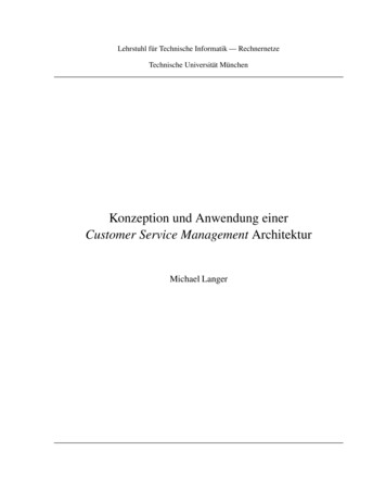
compared to the normal combustion of solid coal. Gasification of coal is a way of increasingthe environmental acceptability of coal as a source of energy.Another advantage of gasification process is that gases are easier to transport than solidfuel. There is a chemical reason that also justifies the conversion of solid to gas. By adding28% of the heating value of pure carbon in the conversion of the solid carbon into the gasphase CO, 72% of heating value of carbon is conserved in the gas. This can be seen by thefollowing reactions: 111KJ/molC 1/2O2 CO 283KJ/molCO 1/2O2 CO2 394KJ/molC O2 CO2(2.1)(2.2)(2.3)The gasification process takes place between 800 and 1800 . The temperature variesaccording to the feedstock used in the process.The process of converting solid carbon to syngas is an endothermic process, called watergas reaction:C H2 O CO H2 131KJ/mol(2.4)By injection of water, a part of the carbon monoxide can be converted into carbon dioxide,thereby producing more hydrogen. This reaction is called water gas shift reaction (WGSR).This is an exothermic reaction: 41KJ/molCO H2 O CO2 H2(2.5)The kinetics of the water gas shift reaction can be modeled using Arrhenius equations. Seeequation 3.14 for details.Integrated Gasification Combined CycleThe Integrated Gasification Combined Cycle (IGCC) is a combination of gasification and acombined cycle plant. Before describing the concept of IGCC, the basic principles of the steamand gas turbine cycles are described.Steam CycleOne of the simplest cycles for energy conversion is the open steam cycle. The thermal energyfor steam generation can be derived from various sources like coal combustion or nuclearenergy. Figure2.1 illustrates the flow scheme and Temperature-Entropy of simple steam cycle.A pump (A) is used to increase the pressure of water to the working pressure of the boiler atpoint B. Boiler supplies heat to the incoming water and raises its temperature to the boilingtemperature (C). The water is evaporated at contact temperature D. The line D-E in T-sdiagram represents superheating of steam. This superheated steam is expanded to atmosphericpressure (line E-F) in a steam turbine. The upper shaded area of the Temperature-Entropydiagram represents the output work. The input heat is represented by the shaded area andthe rectangular area below the line A-F.If a condenser in introduced to form a closed cycle: Rankine Cycle, more work can beextracted. This additional work is represented by the lower shaded area.5
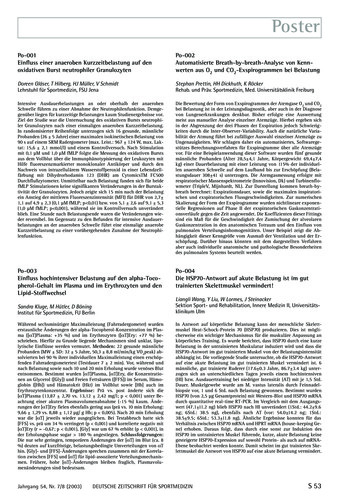
Figure 2.1: Simple Steam Cycle [24]Gas Turbine CyclesFigure 2.2: Gas turbine with open cycle [24]Gas turbines work according to the Brayton cycle[24]. Figure2.2 illustrates the flow schemeand Temperature-Entropy of the Brayton cycle. Compressor compresses the air (A). Thispressurized air(B) is used as oxidant for combustion of fuel. The product gases (C) enter andexpand in the turbine. Due to expansion the temperature of the flue gases decreases. Shaftwork is obtained from the turbine. However the gases leaving turbine have a high energycontent. This simple open gas turbine cycle is used in peaking power stations and aircrafts.The hot gases leaving gas turbine can be used a heat source for steam cycle, in a heatrecovery steam generator (HRSG). This capture of heat increases the overall efficiency to about60%. Figure2.3 illustrates the flow scheme and Temperature-Entropy diagram of a combinedcycle plant. Combined cycle power plants are generally used a base load power station, dueto higher efficiency. Gas turbines used in combined cycle plants can be used with a fewselective fuels like gas and light petroleum distillates. Hence they have limited application.On the other hand gasification can be used to produce the gas required for the gas turbinein a combined cycle plant. Gasification is more robust with respect to the feedstocks such ascoal or heavy oils.6
Figure 2.3: Gas turbine with combined cycle [24]Figure 2.4: Block flow diagram of an IGCC power plant [24]Integrated Gasification Combined CycleThe Integrated Gasification Combined Cycle (IGCC) is a combination of gasification and acombined cycle plant. As explained in the previous section, gasification is used to convertsolid or liquid fuels into gaseous form to be used by gas turbines. Gasification also helps indesulfurizing the fuel. Thus with a gasifier and appropriate gas treatment, it is possible toobtain a fuel that can be combusted in an environment friendly manner comparable to thenatural gas. IGCC plants with coal as feedstock are generally built for a power station. IGCCplants with heavy residual fractions as feedstock are generally built in oil refineries. The flowscheme(Figure2.4) illustrates the concept.The most important integration strategy for most IGCC plants is the integration of thesteam system. The standard steam cycle has an efficiency of 38%. The steam that derivesits heat only from a syngas cooler of a gasifier also has a low efficiency (about 38%). Thisis attributed to the difficulty of superheating the steam in a syngas cooler. Combining bothsteam sources increases the efficiency to about 40%. HRSG is releaved of a large evaporatingload and more saturated steam is superheated in the HRSG.There are other possibilities of integration in IGCC, namely, air integration and nitrogen7
Figure 2.5: Siemens Coal Gasification [21]integration. These involve the use of an air separation unit (ASU).These are described in [24].Due to the increased environment consciousness IGCC also have to take into considerationthe possibilities of carbon capture. The current carbon dioxide sequestration technology isundeveloped for large scale deployment. However IGCC plants have to take this eventualcarbon capture possibility into account.2.2Quenching ProcessThe synthesis gas is produced at high temperatures, depending upon the process and thegasifier used for the gasification process. This high temperature of syngas also makes it difficultto transport the gas for further use in chemical or power application. With the exception ofnatural gas feeds, syngas from gasifier contains various contaminants like particulates, tar,sulphur or chlorine compounds etc. The synthesis gas has to be cleaned of these contaminantsbefore it is usable for chemical industry or as a fuel. Due to the different feedstocks that canused for gasification process, there is also a considerable variation in the contaminants presentin the gas. As an effect of cooling of syngas several heavy contaminants are removed in theform of slag.Due to cooling of the synthesis gas, entrained ash particles will pass through the criticaltemperature range, where the ash becomes sticky. Gas cooling concept has to take this intoconsideration and quench the gas as fast as possible to a temperature at which the ash becomesdry. This is typically about 900 . There are many options for this cooling: quenching,synthesis gas coolers, syngas cooling in oil service. The important aspect of cooling is thetransition stage between slagging and non-slagging conditions. This transition stage has to be8
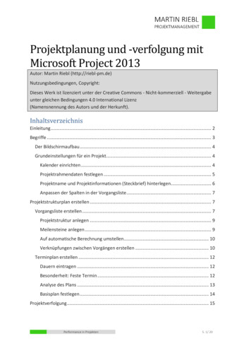
Figure 2.6: Siemens Quencher [24]crossed directly in a way that gas does not contact the wall before it is sufficiently cooled.There are several options for quenching: Radiant gas cooler Water quench Gas quench Chemical quenchThis thesis work is based on water quenching process. This syngas coming out of gasifier iscooled by injecting cold water. Gasification scheme is illustrated in Figure2.5 and a quencherby Siemens is illustrated in Figure 2.6. Water changes from liquid to vapor state. This latentheat of evaporation is extracted from the synthesis gas. There are two type of water quench:partial quenching and total quench.In partial quench, only just enough water is evaporated to decrease the gas temperatureto 900 . The advantage of partial quench is that it allows the sensible heat below 900 inthe syngas to be used for high pressure steam raising in a downstream syngas cooler.In total quench sufficient water is evaporated to saturate the gas with water vapor. It is alow cost and effective solution. However a disadvantage is that heat energy is lost in generatingwater vapor instead of using it productively for some other process or heat exchange. Thiswater vapor is available as contaminated steam and requires extensive cleaning. However ifthe final product is ammonia or hydrogen gas, the water vapor due to total quench is anadvantage, as it avoids the necessity of steam generation for carbon monoxide shift process.The solids present in syngas have to be removed and this can be done by a hot water wash orcandle filters.An important point about water quench (partial or total quench) is that due to water gasshift reaction, carbon dioxide and hydrogen content are increased to some extent.9
Chapter 3Modeling of Quenching Process inCoal GasificationThis chapter describes the procedure of numerical simulation of the quenching process in coalgasification. The process involves spraying of water from injectors into a chamber containingthe feedgas. The water droplets evaporate and react with the syngas (water gas shift reaction2.5). This process can be described in a sentence as: a turbulent multiphase flow with phasechange and reacting species.3.1Physical ProcessesThe simulation of quenching process in coal gasification is a complex process. This involvesproblems of chemistry and the corresponding thermodynamics, turbulence and multiphaseflows. These problems are tightly coupled and non-linear with very small time scales. Sincewater is injected as a high pressure spray in the high temperature gas domain, water evaporatesto form water vapor. This evaporation process takes the energy from the gas phase. Thisinterphase heat transfer requires suitable modeling of energy equations and exchange of energybetween different phases. In addition there is interphase mass transfer. Syngas is generatedat a high temperature.Ideally, thermal radiation should be taken into account to describe the physics as accuratelyas possible. These flows are turbulent in nature. Turbulence can be accounted by variousmeans from direct numerical simulation (which is currently not feasible due to high computingrequirements) to modeling using Reynolds average Navier Stokes equations [13].The Navier-Stokes equations form the basis of the flow. Other conservation equationsare required to describe the reacting flow. A reacting gas is a non-isothermal mixture ofmultiple species which must be tracked individually. The thermodynamic data required forsuch varying temperature is complex and quantities like heat capacity change significantly withtemperature and composition. Different species react and the chemical reaction rates have tobe modeled accordingly. The reacting species also means that the composition of the mixtureis also continuously varying. The problem of chemical reactions tend to be numerically stiff.Different species are characterized by their mass fractions Yk for k 1toN , where N is thenumber of species in the reacting mixture. The mass fractions Yk are defined as: Yk mk /mwhere mk is the mass of species k present in a given volume V and m is the total mass ofgas in this volume.10
Mathematical FormulationThe governing equations for multiphase flow using Eulerian-Lagrangian approach are explainedin this section. The continuous phase and the dispersed phase are governed by differentequations. The Eulerian phase equations are modified form of the Navier-Stokes equationwith additional source terms to account for the multiphase nature of the flow.In fluid mechanics, there are two approaches of dealing with fluids- Eulerian approachand Lagrangian approach. According to Eulerian approach various fields like temperatureor pressure field, can be described as a function of position and time. The field values arephysical properties of position, i.e. every point in the domain has properties as a functionof time. This approach is practically very useful. The Lagrangian approach describes themovement of individual particles by the coordinates dependent on time. The Lagrangianapproach is computationally more expensive.3.2Mathematical Formulation : Eulerian PhaseThe governing equations of multi component mixtures(gas phase) are as follows:Continuity EquationA modified form of continuity equation is used for species transport. The continuity equationis solved for each of the components of the multi component mixture. ρmρm · (ρm u) · ρD fm ρ sm δm1(3.1) tρwhere ρm is the mass density of the species m, ρ is the total gaseous mass density, u is the gasvelocity, fm the source or the sink term term due to chemistry and ρ sm the source term dueto evaporation of the liquid. D is the mass diffusion coefficient and it includes the turbulentdiffusion.P The global continuity equation is obtained by summing up the component densities ρ m ρm ρ · (up) ρ s t(3.2)Momentum EquationThe averaged momentum equation for the gas is given by: (ρu)2 .(ρuu) p .σ F s ρg (ρk)(3.3) t3where p is the gas pressure, σ is the viscous stress tensor, fs is the rate of momentum changeper unit volume due to the spray and g is the specific body force, which is assumed to beconstant.σ 2µS λ · uI(3.4)where1S [ u ( u)T ]2where µ and λ are the first and second coefficients of viscosity.11(3.5)
Energy EquationThe internal energy equation is as follows: (ρe) .(ρue) p · u · J ρe Q̇c Q̇s t(3.6)where e is the specific internal energy (without chemical energy). The source terms Q̇c andQ̇s are due to the chemical heat release and the spray interaction respectively.J is th heat flux vector, which includes head conduction and enthalpy diffusion. Xρmhm (3.7)J κ T ρDρmwhere T is the gas temperature and hm is the specific enthalpy of species m.Turbulence EquationThe Reynolds number is a characteristic number used to define the turbulent nature of theflow. It is defined as follows:ρU DRe (3.8)µwhere ρ is the density of the fluid, U is the velocity of the fluid, D is the characteristic diameterof the flow channel and µ is the dynamic viscosity of the fluid.There are various approaches to account for turbulence in a flow: Reynolds Averages NavierStokes equations (RANS), Large Eddy Simulation(LES) and Direct Numerical Simulation(DNS). The computational complexity and demands of LES and DNS are quite high, therebymaking them not appropriate for industrial simulations. These approaches are typically usedin academic environment for simplified geometries. RANS is the preferred method in industryto deal with turbulent flows. Within RANS approach there are several models to solve theturbulence closure models. [13]Amongst the various models in RANS approach, k is the most popular model[13]. Thismodel involves two transport equations: one for turbulent kinetic energy k and the secondfor dissipation . A modified version of the standard k equations which incorporates thecompressibility effects is used. It is given by the following equations: (ρk)2µ · (ρuk) ρk · u σ u · k ρ Ẇ s(3.9) t3P rk (ρ ) · (ρu ) t i2µ hC 1 C 3 ρ u̇ · C 1 σ u C 2 ρ Cs Ẇ s3P r k(3.10)Chemistry EquationA multicomponent mixture involving chemical reactions may be written asNsXj 10vjkcjNsX00vjkcj , k 1, Nr(3.11)j 1where v 0 is the matrix of the stoichiometric coefficients for the forward reactons, v 00 is thematrix of the stoichiometric coefficients for the backward reacto
ANSYS CFX and ANSYS Fluent. The other major CFD softwares are Star-CCM, Numeca, CFD-Ace and PowerFLOW. OpenFOAM is powerful, popular and object oriented (C ) open-source initiative in CFD. This has led to a considerable amount of academic and indus-trial interest in exploring the capabilities of OpenFOAM. Since it is an open-source code, the