Transcription
snappyHexMesh Basic Trainingsingle Region meshingsimulation of heat transfer withscalarTransportFoam1st edition, Aug. 2015Editor: Philipp Schretter (TU Wien)
OpenFOAM Basic TrainingsnappyHexMeshTutorial One: Single Region MeshingMesh creationThe procedure described in this tutorial is structured in the following order: Creation of the geometry data Meshing a geometry with one single region Run an OpenFOAM simulation with the generated mesh usingscalarTransportFOAMThe reference for this tutorial is a tutorial for meshing in OpenFoam. It is located Mesh/flangeObjectives The aim of the tutorial is to give a basic introduction to single region meshingwith the meshing tool snappyHexMesh.Understanding the advantages of snappyHexMesh No commercial software package is ultimately necessary. For the meshing,the OpenFoam environment is sufficient and no further software isnecessary. The geometry can be created with any CAD program like CATIA,FreeCAD, etc. As the geometry is to be only surface data, the files need tobe in .stl, .nas or .obj. format. The meshing process can be run in parallel mode. If high computationalcapabilities are available, high quality meshes can be generated in littletime.Understanding the three basic steps of snappyHexMesh Castellation: The cells which are beyond a region set by a predefined pointare deleted Snapping: Reconstructs the cells to move the edges from inside the regionto the required boundary Layering: Creates additional layers in the boundary region.Post processingImport your simulation to ParaView. Analyze the heat distribution in the flange1
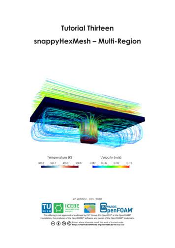
OpenFOAM Basic TrainingsnappyHexMeshStep by step meshingCreation of the .stl filesFor the geometry data, the CAD software CATIA was used, to create the solidgeometry. The creation of the .stl files for single region and multi-region is slightlydifferent. Either way, it is necessary, to create the .stl files as ASCII .stl and not asbinary .stl.For the single region case, only one .stl file for the whole geometry is necessary. Incase the software CATIA is used, the file can easily be created by exporting the fileas .stl. CATIA automatically exports the file as ASCII .stl. Nevertheless, with CATIA,it is not possible to export different surface areas of the flange, for example only theoutside part or the inside part. Therefore, the geometry data is exported from CATIAin .stp format. This .stp file is then read into FreeCAD. With FreeCAD, the .stl filescan be extracted from the .stp solid geometry: Open the .stp geometry file in the draftworkbench and select the object in the tree view view-section. Then click onDowngrade in the combo view view-section. This gives a list of all faces of thegeometry, which can be selected and exported as .ast format. In FreeCAD, it'snecessary to distinguish between .stl, which is binary .stl, and .ast, which is ASCII .stl.In FreeCAD, the surface file is exported in .ast format and afterwards renamed to .stl.2
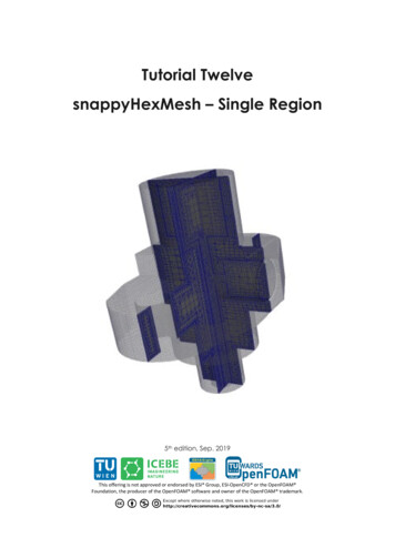
OpenFOAM Basic TrainingsnappyHexMeshFigure 1 Select the surfaces from a solid geometryIn case which was prepared for this tutorial, the dimensions from from the .stl filesexported from the CAD software are in meters. To convert the dimensinos, the opensource software Blender can be used. Therefore, import the .stl files and use the scaletool with a factor 0.001 to convert from m to mm. To export the file, it is necessary totick the box for Ascii to save the .stl file in ascii format. Otherwise, OpenFoam won'tbe able to deal with the file.In the single region case, the header line and the base line of the .stl files, exportedfrom blender need to be updated. For example the headers and baselines in the twoavailable .stl files are renamed to flange outside surface and flange inside surface.This is necessary to have appropriate entries in the boundary file later on for theOpenFoam simulation.In order to create a .stl from a geometry which is already available in gambit, thegeometry data can be exported in .stp or alternatively in .igs format. Afterwards,the .stp or .igs (msbo) file can be imported to FreeCAD and converted via exportas .stl.The technical drawing with the dimensions of the geometry for this tutorial isdepicted below.3
OpenFOAM Basic TrainingsnappyHexMesh4
OpenFOAM Basic TrainingsnappyHexMeshThe folder constant is necessary for the mesh files. The folder system is necessary forthe system settings.constant directoryThe constant directory must initially have the following folders-polyMesh:Which contains the base mesh as blockMeshDict. Here we define a base blockmesh inside. The blockmesh will contain the flange geometry. The dimensionsof the blockmesh are as follows.// * * * * * * * * * * * * * * * * * * * * * * * * * * * * * * * * * * * * * //convertToMeters 1;Eight coordinates of a rectangular blockvertices((-0.03 -0.03 -0.02)(0.03 -0.03 -0.02)(0.03 0.03 -0.02)(-0.03 0.03 -0.02)(-0.03 -0.03 0.02)(0.03 -0.03 0.02)(0.03 0.03 0.02)(-0.03 0.03 0.02));blocks labels the vertices, define number of cells along the axes and expansionratio of cellsblocks(hex (0 1 2 3 4 5 6 7) (30 30 20) simpleGrading (1 1 1));edges();boundary defines different faces if any, based on vertices label. In this case wedo not define different boundaries like 'inlet' 'outlet' etcboundary5
OpenFOAM Basic TrainingsnappyHexMesh(allBoundary{type patch;faces((3 7 6 2)(0 4 7 3)(2 6 5 1)(1 5 4 0)(0 3 2 1)(4 5 6 7));});// ********************** //triSurface:The folder triSurface should contain a file with the geometry data to bemeshed (stl, nas, obj). The file name is to be used as a reference pointer inlater stages.-system directoryThe system directory may have the following files,- controlDict-decomposeParDictIf the mesh is to be run in parallel using the decomposePar utility, this filedefines the parameters for distributed processors- fvSchemes-fvSolution-meshQualityDictminFaceWeight- can be kept at the default value of 0.02.-snappyHexMeshDict:// * * * * * * * * * * * * * * * * * * * * * * * * * * * * * * * * * * //set castellatedMesh, snap, addLayers to true or false depending on thestages ;geometry lists all surfaces except the blockMesh geometry, in theconstant/triSurface directory , and define a name for each of them to beused as referencea refinementBox() can be defined. This is a a region in the blockMeshgeometry which has a refined mesh. The level of refinement of this box isdefined in the section refinementRegions below.geometry{flange single region.stl{type triSurfaceMesh;name flange single region;6
OpenFOAM Basic TrainingsnappyHexMesh}The refinement box has to be larger than one cell of the blockmesh. InOrder to reach a fine region in the blockmesh, several refinementboxes can be defined whereas always a smaller box is refined insidethe refined box. It is always necessary to keep each box larger thanthe smallest cell in that hControls{maxLocalCells 200000;maxGlobalCells 5000000;minRefinementCells 0;maxLoadUnbalance 0.0;nCellsBetweenLevels 1;The section features is used for user-defined edge refinement. It usesThe eMesh files, created with the surfaceFeatureExtract command. These.eMesh files are extracted parts from the .stl surfaces, specified inThe surfaceFeatureExtractDict.Also the extendedFeatureEdgeMesh file from theconstant/extendedFeatureEdgeMesh folder can be used. In this case,bothfiles give the same result.features({file "flange single region.eMesh";level 3;});All surfaces defined in the geometry subdirectory must be listed here.List of the surfaces, which need to be listed in in the boundary filesIn e single region{level (3 3);}}resolveFeatureAngle is an important setting. Edges, whose adjacentsurface normals are at an angle higher than the value set, areresolved. The lower the value, the better is the resolution at sharpedgesresolveFeatureAngle 30;refinementRegions()- the refinement of the refinement box is defined.The cells in this box are split up to the number of levels defined, oruntil the max number of cells is reached. In this case, no refinedregions are defined.refinementRegions{}locationInMesh()- Important coordinate for single region cases, todefine a region which is to be kept from the blockmeshlocationInMesh (6 0 0);allowFreeStandingZoneFaces false;}SNAPPINGImportant parameters are number of mesh displacement iterations,nSolveIterand the number of feature edge snapping iterations, nFeatureSnapIter.snapControls{nSmoothPatch 4;tolerance 1.2;nSolveIter 185;nRelaxIter 6;nFeatureSnapIter 5;7
OpenFOAM Basic TrainingsnappyHexMeshimplicitFeatureSnap false;explicitFeatureSnap true;multiRegionFeatureSnap false;}LAYERINGaddLayersControls{relativeSizes false;layers{The label for the layering is equal to the labeling of theBoundary surface in the boundary file in the constant/polyMeshfolderflange single region flange inside{define the number of surface layersnSurfaceLayers 3;}flange single region flange outside{nSurfaceLayers 3;}}define the expansion ratio of the surface layersexpansionRatio 1.005;define the min and the final thickness of the surface layersfinalLayerThickness 0.0001;minThickness 0.00005;nGrow 0;featureAngle 85;slipFeatureAngle 25;nRelaxIter 5;nSmoothSurfaceNormals 4;nSmoothNormals 3;nSmoothThickness 10;maxFaceThicknessRatio 0.5;maxThicknessToMedialRatio 0.2;minMedianAxisAngle 90;nBufferCellsNoExtrude 0;nLayerIter : If not snapped smoothly enough, the max number of layeraddition iteration can be increasednLayerIter 50;}meshQualityControls{#include "meshQualityDict"nSmoothScale 4;errorReduction ;mergeTolerance 1e-6;// ***************** //-surfaceFeatureExtractDict:// * * * * * * * * * * * * * * * * * * * * * * * * * * * * * * * * * * //flange single region.stl8
OpenFOAM Basic urface;extractFromSurfaceCoeffs{All edges are refined, whose surface normals include angles withless than the angle specified. For the included angels, a speciallevel of refinement can be set in the snappyHexMeshDict in thefeatures subdictionary.includedAngle150;}writeObjyes;}// ****************** //Setting Refinement level in snappyHexMeshDict and surfaceFeatureExtractDictIn the first step, the castellatedMeshControls, the initial mesh can be refined withlevels. The level depends on the refinement set in the blockMesh, and the requiredrefinement on the surfaces. Therefore, levels can be set in the snappyHexMeshsubdirectories features,refinementSurfaces and refinementRegions.Level 0 stands for no refinement and each level splits the cell into 4 separatecells.Figure 2 Refinement level 0, level 1, level 2, level 3Only the relevant changes, which were used in the sample flange case, are commentedin the snappyHexMeshDict. For more information see the literature in [1], [2], [3],[4].The background mesh is created with the command blockMesh. blockMeshTo ensure that also the sharp edges are refined properly, it is very important to createperfect cubes in the first place. In this case, the mesh was created with 30 cells in xand y direction and with 20 cells in z direction. Thus, according to the settings in theblockMeshDict each cube has a length of 2mm in each direction.9
OpenFOAM Basic TrainingsnappyHexMeshFigure 3 Block mesh for flangeOne .stl file is needed with the information about the surfaces inside and outside ofthe flange to set the appropriate boundary conditions. So both surfaces are arecombined to a single file.As mentioned above, this is necessary to have appropriate entries in the boundaryfile. catcad/flange inside.stlcad/flange outside.stlconstant/triSurface/flange single region.stlIn this case, the combined .stl can look similar to the following extract.solid flange insidefacet normal 0 0 0outer loopvertex 0.000000 0.012000 0.007250vertex -0.000422 0.025000 0.007238vertex 0.000000 0.025000 0.007250endloopendfacet.facet normal 0 0 0outer loopvertex 0.000758 0.012000 -0.007210vertex 0.000842 0.025000 -0.007201vertex 0.000422 0.025000 -0.007238endloopendfacetendsolid flange insidesolid flange outsidefacet normal 0 0 0outer loopvertex -0.006500 -0.005000 -0.014250vertex -0.003273 -0.000588 -0.014250vertex -0.003088 -0.000773 -0.014250endloopendfacet.10
OpenFOAM Basic TrainingsnappyHexMesh.facet normal 0 0 0outer loopvertex -0.005437 0.025000 -0.007483vertex -0.004886 0.010000 -0.007854vertex -0.006500 0.010000 -0.006581endloopendfacetendsolid flange outsideThe command surfaceFeatureExtract creates the .eMesh files from the .stl filesand creates the folder extendedFeatureEdgeMesh in the /constant directory. Refiningcertain parts of the surface geometry with the surfaceFeatureExtract tool is optional. surfaceFeatureExtract11
OpenFOAM Basic TrainingsnappyHexMesha)Run snappyHexMesh on one processorThe meshing process with snappyHexMesh can be run in on one processor or onseveral processors in parallel. The command to mesh the flange geometry on oneprocessor is snappyHexMeshThe command snappyHexMesh creates a folder with the mesh files for each meshstep. If, for example, in the snappyHexMeshDict, only castellatedMesh is set to trueand snap and addLayers are set to false, only one folder is created. If also snap is setto true, 2 folders are created and if also addLayers is set to true, 3 folders with 3polyMesh folders are created.In order to avoid the creation of these folders and only keep the final mesh, thefollowing command can be used to overwrite the previous meshing steps. In this case,only one polyMesh folder exits in the /constant directory. snappyHexMesh -overwrite12
OpenFOAM Basic TrainingsnappyHexMeshb)parallelRun snappyHexMesh on several processors inFor running the simulation in parallel, a decomposeParDict file is necessary in thesystem folder. In this file, the decomposition method can be specified. This can behierarchical, simple, scotch or manual.Note: It is recommended, not to use the scotch method to decompose the region.Rather, the hierarchical or the simple method should be used. In case of scotchmethod, errors can occur while executing snappyHexMesh or while reconstructing themesh, so that more domains are reconstructed than have been decomposed before.// * * * * * * * * * * * * * * * * * * * * * * * * * * * * * * * * * * * * * dataFile}(1 2 1);0.001;xyz;(1 2 1);0.001;"cellDecomposition";// *********************** // decomposeParAfter executing decomposePar, the processor* folders are created. The number ofcreated folders are according to the number of subdomains specified in thedecomposeParDict. mpirun -np 2 snappyHexMesh -parallel13
OpenFOAM Basic TrainingsnappyHexMeshTo examine, what each of the steps in the snappyHexMeshDict really does, thefollowing commands can be used.To reconstruct and examine the castelleting step reconstructParMesh -time 1Figure 4 flange mesh for step castellate with surface refinement level 2Figure 5 flange mesh for step castellate with surface refinement level 314
OpenFOAM Basic TrainingsnappyHexMeshTo reconstruct and examine the snap step reconstructParMesh -time 2Figure 6 flange mesh for step snap with surface refinement level 3To reconstruct and examine the layering step reconstructParMesh -time 3In case, only the latest timestep available needed, also the following command can beused reconstructParMesh -latestTimeFigure 7 flange mesh for step addlayers with surface refinement level 315
OpenFOAM Basic TrainingsnappyHexMeshThe figures 4 to 7, are slice views taken with paraview from the center of the flange.The slices are depicted by the red plain in figure XX on the rightFigure 8 flange with sectional plainThe following command only creates a single folder 0 in the processor* folderswhereas the preceding mesh folders 1 or 2 are overwritten.16
OpenFOAM Basic TrainingsnappyHexMesh mpirun -np 2 snappyHexMesh -parallel -overwriteBy overwriting the previous time steps, the mesh can be reconstructed with reconstructParMesh –constantReview the mesh quality with the tool checkMesh checkMeshIn case the checkMesh tool finds erros, the corrupted cells or faces are written tothe folder sets in the folder polyMesh. These cells or faces can be examined withparaview by converting the files to the VTK format.Depending on the sort of corrupted cells depicted in the terminal output fromcheckMesh, the following commands can be used among others foamToVTK –region insideZone –faceSet nonOrthoFaces foamToVTK –region outsideZone –faceSet skewFaces foamToVtK –region insideZone –cellSet zeroVolumeCells17
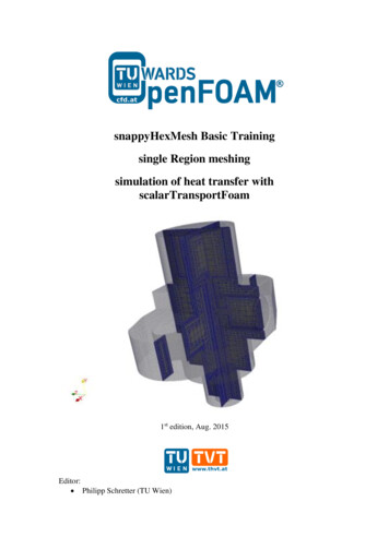
OpenFOAM Basic TrainingsnappyHexMeshRunning OpenFoam simulation with scalarTransportFoamThe mesh files, created with snappyHexMesh are copied to the scalarTransportFoamtutorial sample case pitzDaily which is provided by OpenFoam.Some adjustments are necessary to run the case and check if the mesh quality issatisfactory.Delete the entry defaultFaces in the boundary file in the polyMesh folderIn the controlDict file change the endTime to 0.05 and the writeInterval to100.Update the file temperature where the flange has an initial temperature of293K and is heated up from the inside with 350K. The outside of the flange isadiabatic// * * * * * * * * * * * * * * * * * * * * * * * * * * * * * * * * * * //dimensions[0 0 0 1 0 0 0];internalFielduniform 293;boundaryField{flange single region flange inside{typefixedValue;valueuniform 350;}flange single region flange outside{typezeroGradient;}}// ****************** //-Update the file velocity where the whole velocity in the flange and at theboundaries is zero.// * * * * * * * * * * * * * * * * * * * * * * * * * * * * * * * * * * //dimensions[0 1 -1 0 0 0 0];internalFielduniform (0 0 0 );boundaryField{flange single region flange inside{typefixedValue;valueuniform (0 0 0);}flange single region flange outside{typefixedValue;valueuniform (0 0 0);}}18
OpenFOAM Basic TrainingsnappyHexMesh// ****************** //Run the solver with the command scalarTransportFoamConvert the results with foamToVTK0.01s0.02s0.04s0.03s0.05sFigure 7 Heating of the flange from 0.01 to 0.05s19
OpenFOAM Basic TrainingsnappyHexMeshLiterature[1] h/[2] h[3] acksonSlidesOFW7.pdf[4] mesh#TOC-snappyHexMesh20
With FreeCAD, the .stl files can be extracted from the .stp solid geometry: Open the .stp geometry file in the draft workbench and select the object in the tree view view-section. Then click on Downgrade in the combo view view-section. This gives a list of all faces of the geometry, which can be selected and exported as .ast format.