Transcription
Absolute phase unwrapping for dualcamera system without embeddingstatistical featuresChufan JiangSong ZhangChufan Jiang, Song Zhang, “Absolute phase unwrapping for dual-camera system without embeddingstatistical features,” Opt. Eng. 56(9), 094114 (2017), doi: 10.1117/1.OE.56.9.094114.
Optical Engineering 56(9), 094114 (September 2017)Absolute phase unwrapping for dual-camera systemwithout embedding statistical featuresChufan Jiang and Song Zhang*Purdue University, School of Mechanical Engineering, West Lafayette, Indiana, United StatesAbstract. This paper proposes an absolute phase unwrapping method for three-dimensional measurement thatuses two cameras and one projector. On the left camera image, each pixel has one wrapped phase value, whichcorresponds to multiple projector candidates with different absolute phase values. We use the geometric relationship of the system to map projector candidates into the right camera candidates. By applying a series ofcandidate rejection criteria, a unique correspondence pair between two camera images can be determined.Then, the absolute phase is obtained by tracing the correspondence point back to the projector space.Experimental results demonstrate that the proposed absolute phase unwrapping algorithm can successfullywork on both complex geometry and multiple isolated objects measurement. 2017 Society of Photo-OpticalInstrumentation Engineers (SPIE) [DOI: 10.1117/1.OE.56.9.094114]Keywords: phase unwrapping; fringe projection; phase shifting; epipolar geometry; stereo matching.Paper 170730P received May 12, 2017; accepted for publication Sep. 12, 2017; published online Sep. 28, 2017.1 IntroductionHigh-speed optical three-dimensional (3-D) shape measurement has been widely adopted in many applications rangingfrom online inspection to disease diagnosis.1 Among optical3-D shape measurement techniques, phase-shifting-basedmethods are advantageous because of their high measurement speed, high measurement accuracy, and robustness tonoise or surface reflectivity variations.2For phase-based 3-D shape measurement technologies,phase unwrapping has always been a crucial step for correctly reconstructing 3-D geometry and at the same timea challenging problem. Existing phase unwrapping algorithms are generally divided into two categories: spatial andtemporal phase unwrapping. Spatial unwrapping algorithms3unwrap phase by referring to other pixels on the same phasemap. The unwrapping result depends on the obtained phasequality and, thus, is sensitive to the existence of noise. One ofthe most robust methods is creating a quality map to guidethe unwrapping path such that pixels with higher phase quality will be unwrapped earlier than those with lower phasequality.4 In general, spatial phase unwrapping only producesrelative phase maps. Moreover, the assumption that the phaseis locally smooth makes it inapplicable for measurement ofsurfaces with abrupt depth changes or on multiple isolatedobjects.Temporal phase unwrapping algorithms, on the otherhand, encode the absolute phase value into specific patternsand retrieve the fringe order, the number of 2π’s to be addedfor each point, by analyzing additionally acquired information at a temporally different time. The absolute phase map isobtained since the fringe order is determined by acquiringadditional information rather than referring to the phasevalue of other points. Conventional temporal unwrappingmethods that originated from laser interferometry includetwo to multiwavelength phase-shifting algorithms.5,6 In adigital fringe projection (DFP) system, encoded patternscan be designed in many ways besides sinusoidal patterns,such as a sequence of binary patterns,7 a single statisticalpattern,8 a single stair image,9 etc.Although working robustly on single-camera and singleprojector DFP systems, temporal phase unwrapping isnot desirable for high-speed applications since additionalpatterns acquisition slows down the measurement speed.Currently, with the reduced cost and improved performanceof hardware, researchers have developed alternative absolutephase unwrapping methods by adding a second camera to thesystem, which is often referred to as the multiview method.This multiview system is over-constrained by obtaining morerestrictions from different perspectives, which makes it possible for absolute phase retrieval without temporally acquiring additional patterns. Because two cameras are involved,a standard stereo-vision approach is naturally introducedto determine correspondence points between two camerasand to offer additional conditions for phase unwrapping.It is widely known that passive stereo can easily fail onlow texture surfaces; consequently, the projector projectsother structured patterns (e.g., random dots,10 band-limitedrandom patterns,11 binary-coded patterns,12 color structuredpatterns,13 or phase-shifted sinusoidal fringe patterns14) toactively add surface features on an object and use it fora unique correspondence determination.The aforementioned phase unwrapping methods requireat least one additional image capture for absolute phaseretrieval. To achieve a maximum measurement speed, multiview geometric constraints-based absolute phase unwrapping methods have been recently developed. Instead ofprojecting more patterns, the geometric relationships amongsystem components are employed to obtain more information. A variety of constraints (e.g., wrapped phase, epipolargeometry, measurement volume, phase monotonicity, etc.)are applied to limit the number of candidates for absolute*Address all correspondence to: Song Zhang, E-mail: szhang15@purdue.edu0091-3286/2017/ 25.00 2017 SPIEOptical Engineering094114-1September 2017 Vol. 56(9)
Jiang and Zhang: Absolute phase unwrapping for dual-camera system without embedding. . .phase determination.15–22 Ishiyama et al.18 proposed findingthe closest wrapped phase value for matching points searching. Although easy to implement, a unique correspondencecannot always be guaranteed. Bräuer-Burchardt et al.15enhanced the chance of correct correspondence by applyingphase monotonicity constraints along an epipolar line afterdetermining reference points. Because a backward and forward checking is required to finally select the correct corresponding point out of all candidates, the computation speedis slow. A sequence of studies19–21 found correspondence onphase maps using the trifocal tensor to reject candidatesthrough a mixture of volume constraints, stereo-view disparity range, and intensity difference. These algorithms achievesatisfying robustness on arbitrary shape measurement, butthey are sensitive to phase error, and a time-consumingrefinement process is required for phase error reductionand correspondence coordinate correction. An alternativeapproach is to speed up the searching process by embeddinga statistically unique structured pattern along with the fringepattern for unique correspondence determination.23,24 Whilethis approach works well on correspondence matching, thephase quality is sacrificed due to the embedded statisticalpattern into the fringe pattern.This paper proposes an absolute phase unwrappingalgorithm that addresses these problems from two cameraapproaches. The first step is to calibrate all three devices:both cameras and the projector. Then for each left camerapixel, multiple right camera candidates are generated fromthe system geometric relationship. Given all candidate rejection constraints, the final correspondence pair associatedwith a projector phase line can be obtained for phase unwrapping. Experimental results are provided to demonstrate thesuccess of the proposed method.Section 2 explains the principle of the proposed method.Section 3 shows experimental data, and finally Sec. 4 summarizes this paper.2 PrincipleFigure 1 shows the computational framework of the proposed multiview geometric constraints-based phase unwrapping approach. Essentially, we utilize additional geometricconstraints provided by the second camera to retrieve theabsolute phase. For any pixel on the left camera, its wrappedphase ϕ0 corresponds to a finite number of phase lines onthe projector. An epipolar line is introduced here to limit therange of potential projector candidates. Once the projectorand left camera are calibrated under the same world coordinate, 3-D coordinates ðxw ; yw ; zw Þ of each projector candidate can be reconstructed. Then, a predefined measurementvolume constraint is used to further reduce the number ofcandidates. If the right camera and the projector are alsocalibrated in the same world coordinate, all 3-D points withinthe volume of interest can be projected on the right cameraimage. With employment of various candidate rejectionalgorithms, a final correspondence is determined, and wecan trace it back to the projector space to obtain the absolutephase value.2.1 Least-Squares Phase-Shifting AlgorithmPhase-shifting algorithms are widely used in 3-D opticalmeasurement because of their high speed and high accuracy.2Various phase-shifting algorithms have been developedfor different application needs, such as measurementspeed, measurement accuracy, or sensitivity to disturbance.Typically, using phase shifted patterns with more stepsachieves better phase quality. For an N-step phase-shiftingalgorithm25 with equal phase shifts, the k’th fringe imagecan be mathematically represented asI k ðx; yÞ ¼ I 0 ðx; yÞ þ I 0 0 ðx; yÞ cosðϕ þ 2kπ NÞ;(1)EQ-TARGET;temp:intralink-;e001;326;560where δk ¼ 2kπ N is the phase shift and ϕðx; yÞ is the phaseto be solved.Simultaneously, solving these N equations in a leastsquares manner leads to PN I sinð2kπ NÞϕðx; yÞ ¼ tan 1 PNk¼1 k:(2)k¼1 I k cosð2kπ NÞEQ-TARGET;temp:intralink-;e002;326;485The calculated phase value ϕðx; yÞ is wrapped withinthe ð π; π interval with 2π discontinuities. The real phaseΦðx; yÞ should be a continuous function of ϕðx; yÞ by addingor subtracting an integer number of 2πΦðx; yÞ ¼ ϕðx; yÞ þ 2πkðx; yÞ:(3)EQ-TARGET;temp:intralink-;e003;326;396The integer number kðx; yÞ is called the fringe order, andthis process is called phase unwrapping. If fringe orderkðx; yÞ can be uniquely determined and is consistent with apredefined value in projector space, the unwrapped phase iscalled absolute phase.2.2 Projector Candidate SelectionFor a left camera pixel with a wrapped phase value calculatedfrom the phase-shifting algorithm, we can “guess” itsunwrapped phase by assigning different values for the fringeorder kðx; yÞ in Eq. (3). There is only a finite number of possible fringe orders in the projector image domain, and each ofthem corresponds to one absolute phase line. As long as thecorrect phase line is calculated, the phase value of the line isthe unwrapped absolute phase on this pixel.Fig. 1 Framework of the proposed multiview geometry-based absolute phase unwrapping.Optical Engineering094114-2September 2017 Vol. 56(9)
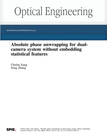
Jiang and Zhang: Absolute phase unwrapping for dual-camera system without embedding. . .(a)(b)PP1P2P3PLOLPRELLeft cameraERORRight cameraFig. 2 Projector candidate selection. (a) Illustrative diagram of epipolar geometry and (b) schematic of projector candidate decision.To reduce the number of candidates, epipolar geometry26is exploited to confine the range of projector mapping points.Epipolar geometry describes geometric constraints on thecorrespondence relationship between two imaging devices.Figure 2(a) shows a schematic diagram of the stereo visionsystem with two cameras capturing images from differentperspectives. For each camera, all light rays converge tothe focal points OL or OR of the lens. Given a pixel PLon the left camera image, all 3-D points that could projecton PL lie on a ray along OL PL . When these 3-D pointsare captured by the right camera, they are also projectedinto a line called the epipolar line (blue line). Connectingimaging point PL with two camera focal points OL andOR forms a plane called the epipolar plane. In fact, the intersection line ER PR between the epipolar plane and the rightcamera imaging plane is the epipolar line.In a conventional structured light system, the right camerais substituted by a projector, but epipolar constraints arestill established. For a given pixel from the left camera, onlypixels along the epipolar line could be potential projectorcandidates, which restricts the searching range. Combinedwith the wrapped phase value of this pixel, we can selectprojector candidates as shown in Fig. 2(b). The solid blueline is the epipolar line from the system geometric relationship, the red dashed lines are phase lines corresponding tothe wrapped phase, and the red intersection points aredecided projector candidates.2.3 Right Camera Candidate ProjectionOnce projector candidates are decided, we map them ontothe right camera image plane, so we can use image information between two cameras to find the true correspondence.Figure 3(a) shows a diagram of the multiview systemincluding two cameras and one projector. For each projectorcandidate ðup ; vp Þ, we first reconstruct the corresponding3-D point ðxw ; yw ; zw Þ based on the triangulation relationship between the left camera and projector. Then, this 3-Dpoint in the world coordinate is projected on a two-dimensional (2-D) image plane of the right camera, denoted asthe point ðuc2 ; vc2 Þ.Both reconstruction and projection are based on a wellknown pinhole model since a nontelecentric lens is used.27Figure 3(b) shows the schematic of the imaging systemthat models the projection from 3-D world coordinate to2-D imaging plane. Mathematically, this projection can bedescribed ass½u; v; 1 T ¼ A½R; t ½xw ; yw ; zw ; 1 T ;(4)EQ-TARGET;temp:intralink-;e004;326;609where s is the scaling factor, ½u; v; 1 T represents the homogeneous image coordinate on the imaging plane, and ½R; t denotes the extrinsic parameters32 32t1r11 r12 r136 776t ¼ 4 t2 5:(5)R ¼ 4 r21 r22 r23 3The extrinsic parameters describe the transformation relationship from the 3-D world coordinate ðxw ; yw ; zw Þ to thecamera lens coordinate ðxc ; yc ; zc Þ by a 3 3 rotation matrixR and a 3 1 translation vector t. The projection from thelens coordinate to the 2-D imaging plane is modeled throughthe intrinsic matrix A32α γ u076(6)A ¼ 4 0 β v0 5;EQ-TARGET;temp:intralink-;e006;326;415001where α and β are the effective focal lengths along the u- andv-axes, γ is the skew factor, and ðu0 ; v0 Þ is the principlepoint.The multiview system also involves the use of a projector.In fact, the projector shares the same pinhole model withthe camera because it has the inverse optics of a camera(the projector projects images instead of capturing images).Consequently, we can build triangulation between the leftcamera and the projector through two sets of equation fromboth devicesFig. 3 Right camera candidate projection. (a) Schematic diagram of the multiview system and (b) schematic diagram of the pinhole model.Optical Engineering094114-3September 2017 Vol. 56(9)
Jiang and Zhang: Absolute phase unwrapping for dual-camera system without embedding. . .sc ½uc ; vc ; 1 T ¼ Ac ½Rc ; tc ½xw ; yw ; zw ; 1 TEQ-TARGET;temp:intralink-;e007;63;752¼ Mc ½xw ; yw ; zw ; 1 T ;ppppppww(7)wto reject wrong candidates and determine the final corresponding points between two cameras: Mask generation. We create a mask to separate objectfrom background and apply this mask on both the leftand right camera phase maps. Any pixel outside themask is regarded as invalid. We do not process anyinvalid pixels on the left camera, and all projected candidates not inside the right camera mask are directlydiscarded. Volume constraint. A predefined measurement volumeas the system working zone is used in the 3-Dreconstruction step. Only 3-D points within the measurement volume will be further projected on the rightcamera. Relative position consistency. To produce anunwrapped phase map, we search all left camera pixelsby raster scanning. On each line, we scan left camerapixel from left to right. Accordingly, the position of theright camera corresponding point should also changefrom left to right monotonously without jumping back.s ½u ; v ; 1 ¼ A ½R ; t ½x ; y ; z ; 1 TTEQ-TARGET;temp:intralink-;e008;63;710¼ Mp ½xw ; yw ; zw ; 1 T :(8)The superscripts c and p represent the camera and projector parameters, respectively. M c and M p are the combination of extrinsic and intrinsic parameters for simplification.In this research, a structured light system calibrationmethod28 is adopted to obtain all extrinsic matrices ½Rc ; tc and ½Rp ; tp and intrinsic matrices Ac and Ap .Once the system is calibrated, we can reconstruct the 3-Dpoint for a given left camera pixel ðuc ; vc Þ and its projectorcandidate ðup ; vp Þ. Equations (7) and (8) provide six equations but with seven unknowns. Recall that each projectorcandidate corresponds to one phase line, which can offeradditional phase constraintup ¼ f½Φðuc ; vc Þ ously, solving Eqs. (7)–(9) can uniquely determine the 3-D coordinate ðxw ; yw ; zw Þ as2 w3 2 c3m11 uc mc31 mc12 uc mc32 mc13 uc mc33 1x6 w7 6 c74 y 5 ¼ 4 m21 uc mc31 mc22 uc mc32 mc23 uc mc33 5EQ-TARGET;temp:intralink-;e010;63;479zwmp11 up mp31 mp12 up mp32 mp13 up mp3332 c cu m34 mc1476 4 vc mc34 mc24 5;pump34 (10)mp14sc2 ½uc2 ; vc2 ; 1 T ¼ Ac2 ½Rc2 ; tc2 ½xw ; yw ; zw ; 1 T :(11)Here, ðxw ; yw ; zw Þ is the 3-D point to be projected; Ac2 and½Rc2 ; tc2 denote intrinsic and extrinsic parameters of theright camera; and ½uc2 ; vc2 ; 1 is the homogeneous coordinateof projected point on the right camera image. We repeat thereconstruction and projection process for all qualified projector candidates as explained in Sec. 2.2. Then, a sequence ofright camera candidates is generated on a 2-D imaging plane.Each candidate corresponds to one absolute phase value, andthe true correspondence point must be within these candidates. As long as the true correspondence point is selected,we can track it back to find the absolute phase on this pixel.2.4 Candidate Rejection and Phase UnwrappingFor each left camera pixel, we find multiple right cameracandidates through the previous steps. Because two candidates have at least a 2π difference on the phase map, theyare relatively separated on the image, which makes themeasy to be distinguished. A list of criteria below is appliedOptical EngineeringΦðx; yÞ ¼ Φðuc2 ; vc2 Þ;(12)x ¼ roundðuc2 Þ;(13)y ¼ roundðvc2 Þ:(14)EQ-TARGET;temp:intralink-;e012;326;441where mcij and mpij represent the i’th row and j’th columnelement in matrices Mc and M p . The 3-D point is then captured by the right camera. In the same way, if we calibratethe right camera under the same world coordinate system,the projection from 3-D coordinate to right camera imagingplane is ruled byEQ-TARGET;temp:intralink-;e011;63;301Once the right camera correspondence ðuc2 ; vc2 Þ isuniquely determined, we can trace it back to find the absolutephase value Φðuc2 ; vc2 Þ from the projector phase line. Sincethe projected point may not be an integer pixel, we round it tothe final correspondence coordinate and assign the phasevalue to this integer pixel ðx; ;temp:intralink-;e014;326;381Here, round() denotes an operator that determines theclosest integer number. Ideally, the corresponding pointsfrom two cameras have exactly the same unwrapped phase,but the practical case is affected by the accuracy of systemcalibration. Therefore, we calculate the fringe order by around operator to achieve a π error tolerance Φðx; yÞ ϕr ðx; yÞkr ðx; yÞ ¼ 8where Φðx; yÞ denotes the projector absolute phase, ϕr ðx; yÞis the right camera wrapped phase, and kr ðx; yÞ representsthe calculated fringe order. Then, the unwrapped phaseΦr ðx; yÞ for the right camera pixel is retrieved byΦr ðx; yÞ ¼ ϕr ðx; yÞ þ 2π kr ðx; yÞ:(16)EQ-TARGET;temp:in
Given a pixel P L on the left camera image, all 3-D points that could project on P L lie on a ray along O LP L. When these 3-D points are captured by the right camera, they are also projected into a line called the epipolar line (blue line). Connecting imaging point P L with two camera focal