Transcription
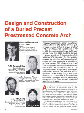
Prestressed ConcreteBridge Design SeminarSession 1 – April 13, 20212a. Fabrication ofPrestressed Concrete Girders1OverviewEconomical fabrication depends on economical design and detailing‐ Process and details of fabrication‐ Design considerations (later presentations)Much info from PCI Bridge Design Manual‐ Chapter 2 – Material Properties‐ Chapter 3 – Fabrication and Construction‐ Chapter 4 – Strategies for EconomyMany fabrication details are possible – a few examples are shown22Prestress Plants331
MaterialsPrestressing strandMild reinforcementConcrete44Prestressing StrandPrestressing strandASTM A416 Grade 270Pretensioned strands andpost‐tensioning anchorages, spirals and ductsStrand shipped in coilsPretensioning and post‐tensioning can becombined as shown here55Mild Reinforcement662
ConcreteConventional methods for proportioning and mixing concrete‐ High strength mixes – up to 10 ksi at 28 days‐ High flow mixes to move through congested reinforcement‐ Rapid strength gain so girders can be removed from the beds quicklyAggregate conveyerBatch plant discharge77FabricationFormsCasting bedsStrands – straight & harpedTensioning & ductsEmbedmentsCasting operations88FormsExternal‐‐‐‐‐‐Side formsSoffitEnd headersAdjustable formsInternal void formsSelf stressing bedInternal‐ Stay‐in‐place‐ Removable993
External FormsGirder side formsBox beam form1010Adjustable FormsSome prestressers use adjustable formsForm to adjust topflange widthHorizontal joint allowsinsertion of filler orhaunched sectionsOther form modifications will be discussed later1111Soffit or Pallet FormsThe soffit is the form for the bottom of the girder‐ Defines the width of bottom flange‐ Supported by and attached to supports12124
End FormsHeaders are usually fabricated of steel to allow reuse‐ Avoid modifying strand patterns‐ Slotted for draping strands‐ Wood may be used ifmodifications are requiredBulb‐tee end form Modification required(header)for skewed ends1313Stay‐In‐Place Internal FormsWaxed cardboardvoid forms forcored slabVoided slab formPolystyrene foam billet fortrapezoidal box beam – alsofor conventional box beams1414Removable Internal FormsPlacing expanded formfor RR box beamRemoving retractedvoid formVoid form forcylinder pile15155
Self‐Stressing FormsForm structure resists the pretensioning force ‐ no abutments required‐ Strand anchor plates bear on formSquare Piling FormDouble‐Tee Form‐ Similar to NEXT Beam1616Prestressing BedThe structure that resists the pretensioning force on the strandsAbutment type bed – most common‐ Abutments are typically fixed in foundation‐ Slab may be used as strut between abutments‐ Typical bed length: 300 – 500 ft long; can be 200 ftDetails for multi‐strand tensioning are shown1717AbutmentsTiedCantilever – most common18186
Strutted‐Type BedRaised structural elements resist forcesPile sectionsused as strutsStrands are in top flangefor haunched pier segmentsof spliced girder bridges‐ Struts provide reaction forStrands at topof haunchedsegmentstrands anchored at levelof strut1919Strand Anchor PlatesAnchor plates span between abutments – major structural elements‐ Strand pattern is set – 2 in. x 2 in. grid is standard‐ Assembly can usually be raised or lowered as needed2020Strand Anchor PlatesSelf‐stressing piling form‐ Strand pattern is set using heavy end plates‐ NEXT Beam is similar21217
Strand AnchorageStrand chucks‐ Reusable type is standard Spring‐loaded at stressing end May use non‐spring‐loaded at dead end‐ Single use‐ Strand splice2222Single Strand TensioningStrands are tensioned from one end of bedSingle strand tensioningwith long ramElongationmeasurementElongation and pressure gagereadings must agree within 5%Pressure gageson pumpElongation for 500 ft bed is 42.6";25.6" for a 300 ft bed2323Multi‐Strand Tensioning & DetensioningAbutmentStrand anchoragesStressing equipmentAlso called “gang” tensioning24248
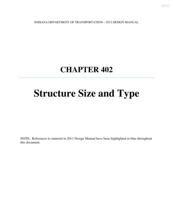
Multiple Strand Tensioning & DetensioningSeparate anchorages for top (draped)and bottom (straight) strandsStressing rams behind the abutmentspull large rods to stress strands2525Straight Strands2626Draped Strands – Hold DownHold down anchoredto rail under bed27279
Draped Strands – Hold UpInternalplateassemblysupportedon palletinside bedExternalA‐framesupportshold‐up2828Draped Strands – Hold UpExample ofinternal platehold up deviceCrane lift pointPinIn raisedpositionwith pinto fixelevationIn loweredpositionRollersIn raised position2929Stressing StrandsAll strands are tensioned in 2 steps‐ Initial tension of 2000 to 4000 lbs, depending on bed length Removes slack and seats dead end chuck Provides reliable starting point for QC readings‐ Remaining stress is then applied to full tension For Grade 270 0.6‐in.‐diam. strands 43.9 kips‐ Corrections may be needed for abutment movement, chuck seating,and temperatureDraped strands will have different forces or elongations from straightstrands, adding complexity to stressing operations303010
DebondingPlastic sleeve or tubing prevents bond between strand and concrete‐ Option for stress control at ends of girders instead of draping‐ Preferred over draping by most fabricators‐ May also be used for top strands in center portion of girderInstallation‐ Must access strands to place and seal with tape‐ Not all strands are easily accessible‐ Ends of sleeves sealed to prevent entry of concrete3131DebondingMaterial‐ Two‐piece snap together sleeves Easy to use‐ Solid tube Placed on strand as installed in bed Not as easy to install‐ Split sleeve (not allowed by some DOTs) Has to be taped for full length to preventconcrete from entering sleeve‐ Ends of all types of sheath must be sealed‐ If sheath is not continuous, joints must also be taped3232Debonding ConsiderationsFor economical design, engineers need to understand how girders aremanufactured in a plant‐ Provide minimum debond length required by design to controlstresses‐ Stagger terminations of debonding to avoid potential cracking‐ Consider access when selecting debonded strands Workers must access strands to apply and seal debonding Special attention may be required for NEXT beams where side forms are fixedand strands can only be accessed from above Discuss with local fabricators333311
EmbedmentsBearing plates and diaphragm holesAdditional barsused to securehole formForm and pipe hangers3434Quality ControlBed setupCross‐section dimensionsStirrup spacing3535Quality ControlMix development &concrete testingSlump testConcrete strength testing363612
Concrete Delivery and PlacementConcrete delivered to and placed in forms‐ Various methods used‐ Units shown do not agitate the concrete, which is delivered by augerConcrete deliveryConcrete placement3737Concrete Delivery and PlacementVibration is typically used to consolidate concreteSelf‐consolidating concrete (SCC) or high slump concrete is often used‐ Facilitates placement, promotes good consolidation, and reducesvibration requirementsInternal vibrationExternal (form) vibration3838Top Flange FinishesTypically the top flange receives a raked finish with minimum amplitudeof ¼ in. for composite behaviorMay be partial width if partial depth prestressed deck panels are used393913
CuringCuring is important‐ Forms are typically covered to retain temperature and moistureAccelerated (elevated temperature or steam) curing may be usedCuring tarps are used to retain heatfor initial curingTheoretical time‐temperaturecurve for accelerated curing4040DetensioningInitial concrete strength, f’ci, must be achieved before detensioningTarps and side forms are removedSingle strand detensioning‐ Workers simultaneously detension eachstrand according to pattern in shop drawings‐ Strands are heated with a torch until wiresrelax and break – they are not cut‐ Specified procedure and pattern‐ Hold downs must be released to avoiddamage as girders shorten and camber4141DetensioningGang detensioning‐‐‐‐Repressurize ramsRelease hardware holding load, then depressurize ramsGirders will move down bed as they are detensionedSince girders move, hold downs must be released to avoid damage May lead to high stresses in girders before strands are detensioned If so, may require additional reinforcement or other measures424214
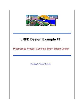
DetensioningGirders camber up and the ends slide on the bed as they are detensioned‐ Initial camber measurements are often made while still on bed‐ Fabricators may lift girder ends before taking camber reading torelieve any drag force at endsSliding can cause spalling at the ends of a girder‐ Bearing plates help prevent spalling‐ Skewed ends on bottom flange should be avoided4343Finishing Girder EndsStrands extendingfrom girder aftertransferStrands cut flush & sealedon ends at expansion jointsStrands burned offwith short projectionson ends cast intodiaphragmFoam recessform for cuttingand patchingstrands4444Quality ControlPost-Pour Non-Conformance Report for Norfolk Southern Box BeamsTindall JobMilepostSmooth Finish -YesPost‐pourinspectionName:Product Type, Mark & Position No.'s:Date:NoBallast Curbs -YesTop ( /- 1/4")Flush against beam ( /- 1/2")Sides & ends ( /- 1/8")Smooth finish ( /- 1/8")Bottom ( /- 1/8")NoChamfered edgesChamfered edgesNo cracksNo cracksNo honeycombNo honeycombWidth ( /- 3/8")End of strands epoxiedHeight ( /- 3/8")Clean - top & all sidesLocation of holes ( /- 1/2")Clean - inside of voidHoles plumbHoles open & cleaned outDimensions -Location of joints ( /- 3/8")Length ( 1/4", - 1/2")Joints cleaned outWidth ( /- 1/4")Scuppers cleaned outProduct trackingDepth ( /- 1/4")Web thickness ( /- 1/2")Stencil -Flange thickness ( /- 1/2")Correct Job No. & MilepostAll sides square ( /- 3/8")Correct dateAll sides plumb ( /- 3/8")Correct mark & position no.Correct lengthHoles -Correct lifting weightLocation ( /- 1/4")Correct location on productCenter to center ( /- 1/2")Plumb ( /- 1/2")Dunnaged properlyOpened & cleaned outOther Notes Lift Loops Height ( 0", - 2")Location ( /- 1")RFID tagBlockoutsApproved by Q.C. (initial & date)Reviewed Tensioning Report (initial & date)Reviewed Concrete Test Report (initial & date)SlumpAirTemp.Approved by NS Representative (initial & date)Batch ReportRelease Break:PSI28 Day Break:PSITemperature ReportPos 1Pos 2Pos 3Pos 4Pos 5Pos 6454515
Fabrication Defects and RepairsPCI Repair Manual (MNL 137‐06)This guide helps provide auniform assessment andapproach to fixing many defectsto ensure that responses aremeasured, appropriate and cost‐effective for the situation.Currently being updatedDiscussed in later presentation4646Handling and TransportationPlant Handling and Storage‐ Lift points‐ Storage & stackingTransportation‐ Trucking‐ Barge‐ Rail4747Lifting and StorageLifting loops and other lifting devicesTypical strand loopsRigid lifting devicesSling484816
Lifting and StorageStacking & StoragePrecast deckpanelsGirders ondunnage inplant4949ShippingStacking & StorageLoading girder ona truckSpecialized equipmentis used5050ShippingRemotely steered trailer515117
Shipping ConsiderationsIncrease overhang over supports to improve stability‐ Need to consider stresses‐ Full f’c is usually available by time of shippingSeveral methods to attach girder to hauling equipment‐ Fabricator may request holes through web or flange5252Shipping ConsiderationsShipping route‐‐‐‐‐Will load be permitted on route?Length of girder for curves and obstaclesRoll stiffness of the hauling systemConsider superelevation along routeAccess to the siteIf questions – discuss with fabricator and/or hauling contractorsIssues related to lateral stability are discussed in later presentation5353Shipping Record Length Girders210 ft long single‐piece girder ‐ NU 2800 (110 in.)545418
New Record Longest Single‐Piece Girder in USMod WSDOT WF100G – 223 ft long at CL; add 7 ft for skew‐ LWC was used to reduce weight for haulingSee article in Fall 2019 issue of ASPIRE5555Barge & RailBarge loaded withbeamsBarge loaded with pilesLoading box beamson railcarLoad must bebalanced5656InstallationJobsite Handling‐ Crane lifting‐ Launching truss‐ ShoringConnectionsTwo‐crane liftOne‐crane liftwith long slingsLateral StabilityOne‐crane liftwith spreader bar575719
Launching Beam or TrussSetting precast beam with launching beam‐ Crane lifts girder fromtruck and sets on dollyon the launching beam‐ Truck backs up to pushgirder across launchingbeam where it can bepicked by crane atother end5858Launching Beam or TrussLaunching beamon steroids inOregon5959Launching Beam or TrussPlacing one endof girder on dollyon launchingbeamTruck will backup to push itacross launchingbeam606020
Launching Beam or TrussTwo cranes liftgirder whiledollies arerepositioned6161Launching Beam or TrussMotorized dolliesmove girder acrossthe launching beamsto the next spanPhotos are from thelate Dr. KeithKaufman with KnifeRiver PS in OR6262Launching Beam or TrussUsing load triangle to pass girder between two cranes636321
Launching Beam or TrussUsing load triangle to pass girder between two cranes6464ShoringShoringStrongbackTemporary support towerfor spliced girder erection6565SummaryKeys to economical prestressed concrete bridges‐‐‐‐‐Understanding production of girdersProper design and detailingLocal availability of productsRepetitive useOpen communicationsContact your local fabricators!666622
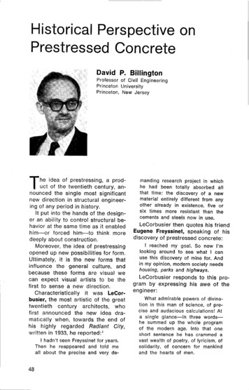
Crane LiftingPop quiz!!Why are they having to use a come‐alongalong to set this girder?‐ Girder is being set with a single cranepickwith inclined leads‐ Far end of girder is higher, soit is already on the bearing‐ Inclined pick on this endcreates thrust6767Prestressed ConcreteBridge Design SeminarSession 1 – April 13, 20212a. Fabrication ofPrestressed Concrete GirdersQuestions?6823
Pos 1 Pos 2 Pos 3 Pos 4 Pos 5 Pos 6 RFID tag 43 44 45. 16 46 Fabrication Defects and Repairs PCI Repair Manual (MNL 137 . measured, appropriate and cost . ‐Roll stiffness of the hauling system