Transcription
ACI Education Bulletin E2-00(Reapproved 2006)REINFORCEMENT FOR CONCRETE—MATERIALS AND APPLICATIONSDeveloped by Committee E-701,Materials for Concrete ConstructionCharles K. Nmai, ChairmanDavid M. Suchorski, SecretaryLeonard W. BellTarek S. KhanKenneth B. RearRichard P. BohanPaul D. KraussRaymundo Rivera-VillarrealDavid A. BurgColin L. LoboJere H. RoseDarrell F. ElliotStella Lucie MarusinPaul J. TikalskyJames ErnzenPatrick L. McDowellMark E. VincentJames A. FarnyGerald R. MurphyChristopher H. WrightJose Pablo GarciaAnthony C. Powers*Morris Huffman*Kari L. YuersRobert C. ZellersSubcommittee Chairman.CONTENTS3.2—Fiber-reinforced polymer (FRP) bars3.2.1—FRP materials3.3—Fiber reinforcement3.3.1—Applications3.3.2—Steel fibers3.3.3—Synthetic fibers3.4—Materials for repair and strengthening of structuralconcrete members3.4.1—External steel reinforcement3.4.2—FRP plates, sheets, and jacketsPreface, p. E2-2Chapter 1—Introduction, p. E2-21.1—DefinitionsChapter 2—Structural concrete: Plain, reinforced,and prestressed, p. E2-32.1—Plain concrete2.2—Reinforced concrete2.2.1—Bending and bending stresses in reinforced concretemembers2.2.2—Other reinforcement applications2.3—Prestressed concrete2.3.1—Bending and bending stresses in prestressed concretemembers2.3.2—Advantages of prestressed concrete2.3.3—Pretensioned and post-tensioned concrete2.4—Other prestressing applicationsChapter 4—Prestressing materials, p. E2-124.1—Steel4.1.1—Seven-wire ength4.2.2—Applied loadsChapter 3—Reinforcing materials, p. E2-63.1—Steel reinforcement3.1.1—Deformed steel bars3.1.2—Threaded steel bars3.1.3—Welded wire fabricChapter 5—Corrosion-resistant reinforcement,p. E2-145.1—Epoxy coating5.2—Galvanizing5.3—Stainless steel5.4—Chemical and mineral corrosion protection systemsThe Institute is not responsible for the statements oropinions expressed in its publications. Institute publicationsare not able to nor intended to supplant individual training,responsibility, or judgment of the user, or the supplier of theinformation presented.ACI Education Bulletin E2-00.Copyright 2000, American Concrete Institute.All rights reserved including rights of reproduction and use in any form or by anymeans, including the making of copies by any photo process, or by electronic or mechanical device, printed, written, or oral, or recording for sound or visual reproduction or foruse in any knowledge or retrieval system or device, unless permission in writing isobtained from the copyright proprietors. Printed in the United States of America.E2-1
E2-2ACI EDUCATION BULLETINChapter 6—Storage and handling, p. E2-146.1—Uncoated steel reinforcement6.2—Epoxy-coated steel reinforcement6.3—FRP6.4—Fiber reinforcementChapter 7—References, p. E2-15PREFACEThis document is an introductory document on the topic ofcommonly used materials for reinforcement of concrete. Thisprimer describes the basic properties and uses of these materials.It is targeted at those in the concrete industry not involved indesigning with or specifying these materials. Students,craftsman, inspectors, and contractors may find this a valuableintroduction to a complex topic. The document is not intendedto be a state-of-the-art report, user's guide, or a technicaldiscussion of past and present research findings on the subject.More detailed information is available in ACI CommitteeReports listed in Chapter 7, References.CHAPTER 1—INTRODUCTIONNearly everyone involved in construction knows that reinforcement is often used in concrete. However, why it is usedand how it is used are not always well understood.This bulletin provides some of the information important tounderstanding why reinforcement is placed in concrete. Mostconcrete used for construction is a combination of concreteand reinforcement that is called reinforced concrete. Steel isthe most common material used as reinforcement, but othermaterials such as fiber-reinforced polymer (FRP) are alsoused. The reinforcement must be of the right kind, of the rightamount, and in the right place in order for the concrete structure to meet its requirements for strength and serviceability.In this document, frequent references are made to standardsof the American Society for Testing and Materials (ASTM).These include test methods, definitions, classifications, andspecifications that have been formally adopted by ASTM.New editions of the ASTM Book of Standards are issuedannually and all references to these standards in this bulletinrefer to the most recent edition. Other agencies have similar oradditional standards that may be applicable.1.1—DefinitionsCertain terms will be used throughout this bulletin withwhich familiarity is important. A few of the more commonand most frequently used are listed in this section. Precisetechnical definitions may be found in ACI 116R, “Cement andConcrete Terminology.”bar size number—a number used to designate the bar size.Reinforcing bars are manufactured in both InternationalSystem (SI—commonly known as metric—measured in millimeters), and U.S. customary (in.-lb) sizes. The bar number formetric bar sizes denotes the approximate diameter of the barin millimeters. For example, a No. 13 bar is about 13 mm indiameter (actually 12.7 mm). U.S. customary bar sizes No. 3through No. 8 have similar designations, the bar numberdenoting the approximate diameter in eighths of an inch (forexample, a No. 5 bar is about 5/8 in. in diameter).bent bar—a reinforcing bar bent to a prescribed shape,such as a straight bar with a hooked end.compression—a state in which an object is subject to loadsthat tend to crush or shorten it.compression bar—a reinforcing bar used to resistcompression forces.compressive strength—a measure of the ability of theconcrete to withstand crushing loads.elastic limit—the limit to which a material can be stressed(stretched or shortened axially) and still return to its originallength when unloaded. Loads below the elastic limit result inthe material being deformed in proportion to the load. Materialstretched beyond the elastic limit will continue to deformunder a constant, or even declining, load.fibrillated fibers—synthetic fibers used to reinforceconcrete that are bundled in a mesh resembling a miniaturefish net.FRP reinforcement—reinforcing bars, wires or strandmade from fiber-reinforced polymer (FRP). (Originally, the“p” in FRP stood for “plastic,” but “polymer” is now thepreferred term to avoid confusion.)monofilament fibers—discrete individual fibers used toreinforce concrete.post-tensioning—a method of prestressing in which thetendons are tensioned after the concrete is hardened.prestressed concrete—Structural concrete in whichinternal stresses (usually compressive stresses) have beenintroduced to reduce potential tensile stresses in the concreteresulting from loads. This introduction of internal stresses isreferred to as prestressing and is usually accomplishedthrough the use of tendons that are tensioned or pulled tightprior to being anchored to the concrete.pretensioning—a method of prestressing in which thetendons are tensioned before concrete is hardened.rebar—an abbreviated term for reinforcing bar.reinforced concrete—structural concrete with at least acode-prescribed minimum amount of prestressed or nonprestressed reinforcement. Fiber-reinforced concrete is notconsidered reinforced concrete according to this definition.secondary reinforcement—nonstructural reinforcementsuch as welded wire fabric, fibers, or bars to minimize crackwidths that are caused by thermal expansion and contraction,or shrinkage. Secondary reinforcement is reinforcement usedto hold the concrete together after it cracks. Structuralconcrete with only secondary reinforcement is not consideredreinforced concrete.steel fibers—carbon or stainless steel fibers used in fiberreinforced concrete meeting the requirements of ASTM A 820.structural concrete—all concrete used for structuralpurposes including plain and reinforced concrete.tendon—a wire, cable, bar, rod, or strand, or a bundle ofsuch elements, used to impart prestress to concrete. Tendonsare usually made from high-strength steel, but can also bemade from such materials as FRP.tensile strength—a measure of the ability of a material (forexample, concrete or reinforcement) to withstand tension.
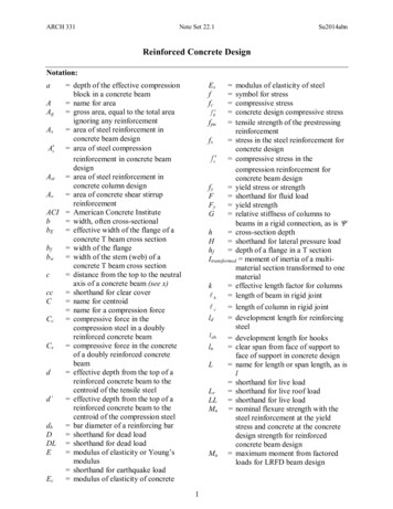
REINFORCEMENT FOR CONCRETEFig. 2.2—Examples of plain and reinforced concrete: plaincurb and gutter (left) and reinforced concrete T-beam(right).E2-3Fig. 2.2.1(a)—A simple beam loaded in the middle andsupported at the ends will tend to deflect or bend down inthe middle, causing tensile stress in the bottom of the beamand tending to pull it apart. That is, the bottom of the beamis in tension. Reinforcing steel near the bottom of the beamwill resist this tension and hold it together.Tension in both the concrete and reinforcement results whenreinforced concrete bends under loading.tension—a state in which a material is subject to loads thattend to stretch or lengthen it.yield strength—The stress required to stretch a material toits elastic limit.CHAPTER 2—STRUCTURAL CONCRETE: PLAIN,REINFORCED, AND PRESTRESSEDThe design and construction of structural concrete, bothplain and reinforced (including nonprestressed andprestressed concrete) is covered by ACI 318, Building CodeRequirements for Structural Concrete, and ACI 301, Standards Specification for Structural Concrete.2.1—Plain concretePlain concrete is structural concrete without reinforcementor with less than the minimum amount required by ACI 318for reinforced concrete. It is sometimes used in slabs-ongrade, pavement, basement walls, small foundations, andcurb-and-gutter.2.2—Reinforced concretePlain concrete (Fig. 2.2) has compressive strength—theability to resist crushing loads; however, its tensile strength isonly about 10% of its compressive strength. Its tensile strengthis so low that it is nearly disregarded in design of most concretestructures. Reinforced concrete is a combination of adequatereinforcement (usually steel bars with raised lugs called deformations) and concrete designed to work together to resistapplied loads (Fig. 2.2). Properly placed reinforcement inconcrete improves its compressive and tensile strength.2.2.1 Bending and bending stresses in reinforced concretemembers—Many structural members are required to carryloads that cause bending stresses. An example is a simplysupported beam, in which the top of the member is subjectedto compression lengthwise while the bottom is subjected totension lengthwise (Fig. 2.2.1(a)). This is referred to as beamaction and can be illustrated by supporting a board at each endand breaking it by applying a heavy load to the center. If theboard is loaded at each end and supported in the middle, as ina cantilevered beam, the top of the board over the support is intension and the bottom is in compression (Fig. 2.2.1(b)).Unreinforced concrete structural members have littlecapacity for beam action because concrete’s low tensileFig. 2.2.1(b)—If the beam is supported in the middle and theends are loaded (as in a cantilever beam, such as abalcony), the top of the beam over the support is in tensionand will pull apart or crack if there is no reinforcing steelnear the top of the beam.Fig. 2.2.1(c)—Properly placed reinforcement in this cantilever beam will resist tension and control cracking.Fig. 2.2.1(d)—Incorrectly placed or missing reinforcementis not effective in resisting tension and will allow uncontrolled cracking in the beam.strength provides little resistance to the tensile stress in thetension side of the member. This is one of the most importantfunctions of reinforcement in concrete members—to resistthe tension in these members due to beam action (Fig. 2.2.1(c)).Steel is remarkably well- suited for concrete reinforcementbecause it has high tensile strength, and therefore relativelysmall amounts are required. Also, concrete bonds to steel,and both expand and contract to about the same degree withtemperature changes. The good bond between concrete andsteel allows an effective transfer of stress or load betweenthe steel and concrete so both materials act together inresisting beam action. For these reasons, steel is the most
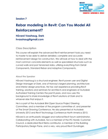
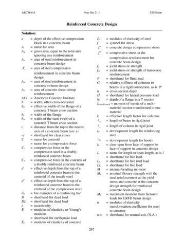
E2-4ACI EDUCATION BULLETINcommon material used to reinforce concrete. However, othermaterials such as FRP are also used for reinforcement.Many structural members must perform like a beam tofulfill their function in the structure. Among such concretestructural members are beams, girders, joists, structural slabsof all kinds, some columns, walls that must resist lateral loads,Fig. 2.2.2(a)—Reinforcement in a concrete column (courtesyof HDR Engineering, Inc.).and more complex members such as folded plates, arches,barrels, and domes. In addition to unintentional omission ofpart or all of the reinforcement, improper placement of thereinforcement designed to resist tension is one of the mostcommon causes of structural concrete failures (Fig. 2.2.1(d)).If the tensile steel is not properly placed in the tension zone ofa structural member, it will not be effective in resistingtension, and failure may occur.2.2.2 Other reinforcement applications—In addition to itsuse to resist tension in structural members, reinforcement isused in concrete construction for other reasons, such as: To resist a portion of the compression force in a member.The compressive strength of steel reinforcement is about20 times greater than that of normal-strength concrete. Ina column, steel is sometimes used to reduce the size ofthe column or to increase the column’s carrying capacity(Fig. 2.2.2(a)). Compression steel is sometimes used inbeams for the same reasons. To resist diagonal tension or shear in beams, walls, andcolumns. Reinforcement used to resist shear in beams iscommonly in the form of stirrups (Fig 2.2.2(b)), but mayalso consist of longitudinal reinforcement bent up at anangle near the ends of the beam, or welded wire fabric.In columns, shear reinforcement is typically in the formof ties, hoops, or spirals.Fig. 2.2.2(b)—Stirrups to resist shear in a concrete box girder bridge (courtesy HDR Engineering, Inc.).
REINFORCEMENT FOR CONCRETEE2-5Fig. 2.2.2(c)—Hoop reinforcement in a reinforced concretecolumn (courtesy of HDR Engineering, Inc.). To resist bursting stresses resulting from high compressiveloads in columns or similar members, in which spiral steelreinforcement, hoops (Fig. 2.2.2(c)), or ties are used. To resist internal pressures in round structures such ascircular tanks, pipes, and bins. To minimize cracking, or more precisely, to promotenumerous small cracks in place of fewer large cracks, inconcrete members and structures. To limit widths and control spacing of cracks due tostresses induced by temperature changes and shrinkage(shortening of the concrete due to drying over time) inslabs and pavement.2.3—Prestressed concretePrestressed concrete is structural concrete in which internalstresses have been introduced to reduce potential tensilestresses in the concrete resulting from loads. This introductionof internal stresses is called prestressing and is usually accomplished through the use of tendons that are tensioned or pulledtight prior to being anchored to the concrete. Tendons canconsist of strands, wires, cables, bars, rods, or bundles of suchelements. Tendons are usually made from high-strength steel,but can also be made from other materials such as FRP.2.3.1 Bending and bending stresses in prestressed concretemembers—As with reinforced concrete members, the mostcommon type of prestressed members are bending membersor beams. The tendons in prestressed concrete beams, like thenonprestressed reinforcement in reinforced concrete beams,are placed near the top or bottom of the beam where theapplied loads will cause tension. For example, in a beam spanning between two supports carrying a load in the middle, theload would cause tension at the bottom of the beam, so thetendons would be placed near the bottom of the beam to resistthis tension (Fig. 2.3.1). Similarly, in a beam supported at thecenter and loaded at the ends, the loads would cause tensionon the top part of the beam, so the tendons would be placednear the top of the beam to resist this tension. The differencebetween the reinforced concrete beams and the prestressedconcrete beams in these examples is that, in the nonprestressedFig. 2.3.1—In a prestressed simple beam, the prestressingsteel is placed near the bottom of the beam, just like regularreinforcing steel. But in the prestressed beam, theprestressing causes the unloaded beam to bend upward inthe middle, opposite to the downward bending caused by theapplied load. The combined effect is a beam that bends less,and therefore cracks less, under load.beams, the reinforcement is not subjected to tension until thebeam is loaded, whereas in the prestressed beam, the tendonsare tensioned before the beam is loaded. By tensioning thetendons before loading the beam, the concrete on the side ofthe beam with the tendons is squeezed or compressed. Whenthe beam is loaded, the tension in the concrete caused by theload is offset by the compression caused by the prestress.2.3.2 Advantages of prestressed concrete—There are severalbenefits to prestressing concrete: Prestressed beams make more efficient use of the bestqualities of the concrete and tendons (that is, thecompressive strength of concrete and the tensile strengthof steel). Therefore, a prestressed beam using a givenamount of concrete can be made stronger than a comparable reinforced concrete beam. A prestressed concrete beam can be designed such thatthe cracks in the concrete due to applied loads aresmaller than in a comparable reinforced concrete beam,or can be virtually eliminated. This makes for a moredurable, longer lasting member by preventing water,chlorides (deicing salt), and other corrosive materialsfrom coming into contact with the tendons.
E2-6ACI EDUCATION BULLETINCHAPTER 3—REINFORCING MATERIALSVarious materials are used to reinforce concrete. Roundsteel bars with deformations, also known as deformed bars,are the most common type of reinforcement. Others includesteel welded wire fabric, fibers, and FRP bars. It is importantto note that not all structural concrete containing reinforcement meets the ACI Building Code (ACI 318) definition ofreinforced concrete. Prestressed beams, particularly pretensioned ones, arefrequently made in a factory and shipped to the construction site. The quality of the formwork and concrete, and theplacement of the prestressed and nonprestressed reinforcement, can be better controlled in a factory setting than atthe construction site, resulting in a higher-quality structure.2.3.3 Pretensioned and post-tensioned concrete—Concreteis prestressed by one of two general methods: pretensioningand post-tensioning. When concrete is pretensioned, thetendons are stressed in the form before concrete is placed.When concrete is post-tensioned, the tendons are stressed afterconcrete is hardened.2.3.3.1 Pretensioned concrete—Pretensioning is usuallyperformed in a factory (or precasting yard). The tendons areheld in place and tensioned against the ends of the casting bedbefore the concrete is placed. Because the tensile force in thetendons is very high, very strong temporary anchorages areneeded; these would be difficult to provide at a constructionsite. After the concrete has achieved adequate strength, thetemporary anchorages are released, or the tendons are cutoutside of the concrete, transferring the prestress force fromthe ends of the casting bed to the concrete. In pretensionedbeams, the tendons usually consist of seven-wire strands that,after release of the temporary anchorages, are anchored by bondto the concrete. Advantages of pretensioned concrete are that itdoes not require the use of permanent anchorages and that thetendons are bonded to the concrete over their entire length.2.3.3.2 Post-tensioned concrete—Post-tensioning isusually performed at the job site. Post-tensioning tendons areusually internal but can be external. Internal tendons areplaced within plastic or metal ducts embedded in the concreteand tensioned against the hardened concrete. Internal tendonsare usually bonded, but can be unbonded. After tensioning,bonded tendon ducts are filled with cement grout to preventsteel corrosion. Unbonded tendons are not grouted. Externaltendons are not necessarily placed in ducts, but are attached tothe concrete only at the anchorages and at changes in direction(deviators). Post-tensioning requires special hardware at theends of each tendon to anchor the tendon to the concrete.Nonprestressed reinforcement is usually required in theconcrete behind the anchor plates to resist localized forces inthis area, sometimes referred to as the anchorage zone.Some of the advantages of post-tensioning are that it doesnot require the large temporary anchorages required forpretensioning, it allows exploitation of the flexibility inherentto cast-in-place concrete construction, and it allows for largermembers than are possible in a precasting plant.3.1—Steel reinforcementSteel reinforcement is available in the form of plain steelbars, deformed steel bars, cold-drawn wire, welded wirefabric, and deformed welded wire fabric. Reinforcing steelmust conform to applicable ASTM standard specifications.3.1.1 Deformed steel bars—Deformed bars are round steelbars with lugs, or deformations, rolled into the surface of thebar during manufacturing. These deformations create amechanical bond between the concrete and steel. Deformedsteel bars (Fig. 3.1.1) are the most common type of reinforcement used in structural concrete.3.1.1.1 Deformed bar sizes—Deformed steel bars aredesignated in both SI (metric) and U.S. customary (in.-lb)sizes, according to ASTM A 615M/A 615, A 706M/A 706,and A 996M/A 996. In other words, metric bar sizes representa soft conversion of U.S. customary bar sizes. Metric bars areexactly the same size as corresponding U.S. customary bars,but are given a metric designation (bar number and grade).The bar number for both metric and U.S. customary bar sizesdenotes the approximate diameter of the bar in millimeters andeighths of an inch, respectively. (For U.S. customary bar sizesNo. 4 through No. 8, the relationship between bar number andbar diameter in eighths of an inch is exact—the bar number isexactly the number of eighths of an inch in the bar diameter.However, for U.S. customary bar sizes No. 9 through No. 18,the bar number is the number of eighths of an inch in the diameter closest to the actual diameter.) For example, a No. 13metric bar is approximately 13 mm in diameter and is exactlythe same size as a No. 4 U.S. customary bar, which is 4/8 or 1/2in. in diameter. Similarly, a No. 32 metric bar is approximately32 mm in diameter and is exactly the same size as a No. 10U.S. customary bar, which is 1.27 in. in diameter, or approximately 10/8 or 1-1/4 in. There are 11 bar sizes. The 11 metricsizes are No. 10, 13, 16, 19, 22, 25, 29, 32, 36, 43, and 57. Thecorresponding U.S. customary sizes are No. 3 through No. 11,No. 14, and No. 18. Note that the six metric bar sizes from No.10 through No. 25 (corresponding to No. 3 through No. 8 U.S.customary bars) are in 3 mm (1/8 in.) increments and that thedesignation numbers for these bars are three times the bar2.4—Other prestressing applicationsIn addition to its use to resist tension in bending members,prestressing is used in concrete construction for other functions,such as: To resist internal pressures in circular structures such ascircular tanks, pipes, and bins. To limit cracking in bridge decks and slabs-on-grade. To improve capacity of columns and piles. To reduce long-term deflections.Fig. 3.1.1—Typical deformed reinforcing bar (courtesy ofConcrete Reinforcing Steel Institute).
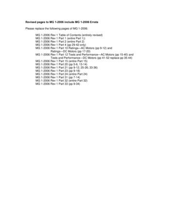
REINFORCEMENT FOR CONCRETEE2-7Table 3.1.1.2(a)—ASTM standard reinforcing barsASTM designationTypeA 615M/A 615BilletA 706M/A 706Low-alloyA 996M/A 996RailA 996M/A 996AxleMetric grades Metric sizes U.S. customary grades U.S. customary sizes30042052010 - 1910 - 5719 - 574060753-63 - 11, 14, 186 - 11, 14, 1842035042030042010 - 5710 - 2510 - 2510 - 2510 - 2560506040603 - 11, 14, 183-83-83-83-8Table 3.1.1.2(b)—Bar marksMarkSymbol or series ofsymbolsNumberS, W, “rail symbol” or“rail symbol” and R, ABlank or numberMeaningDesignates producer’s millDesignates bar sizeDesignates type of steel(S - billet-steel, W - low-alloy steel, “railsymbol” or R - rail-steel, or A - axle steel)Grade mark (blank for Grade 300/Grade 40and Grade 350/Grade 50, otherwise thegrade number).number of their corresponding U.S. customary bar, plus one.Also note that there is a No. 10 bar in both U.S. customary andmetric units, but the U.S. customary No. 10 bar is more thanthree times as large as the No. 10 metric bar.3.1.1.2 Deformed bar grades and availability—Deformed steel bars are furnished in four metric strengthgrades of steel: 300, 350, 420, and 520, having minimum yieldstrengths of 300, 350, 420, and 520 MPa, respectively. Thefour corresponding U.S. customary grades: Grades 40, 50, 60,and 75, have minimum yield strengths of 40,000, 50,000,60,000, and 75,000 psi, respectively. They are manufacturedfrom four types of steel: billet steel (ASTM A 615M/A 615),low-alloy steel (ASTM A 706M/A 706), and rail and axle steel(ASTM A 996M/A 996).Billet-steel bars are available in three metric grades andthree equivalent U.S. customary grades. They are available inmetric bar sizes No. 10 through No. 19 in Grade 300, in all barsizes in Grade 420, and in bar sizes No. 19 through No. 57 inGrade 520 (Table 3.1.1.2(a)). Billet-steel bars are available inU.S. customary bar sizes No. 3 through No. 6 in Grade 40, inall bar sizes in Grade 60, and in bar sizes No. 6 through No. 18in Grade 75.Low-alloy-steel bars are manufactured in all sizes, but in onlyone metric grade (420) and one equivalent U.S. customarygrade (60). Availability of ASTM standard metric and U.S.customary reinforcing bars is summarized in Table 3.1.1.2(a).Rail-steel bars are manufactured by rolling used railroadrails, and are available in two metric grades (350 and 420) andtwo equivalent U.S. customary grades (50 and 60). They areavailable in metric bar sizes No. 10 through No. 25 and in U.S.customary bar sizes No. 3 through No. 8.Axle-steel bars are manufactured by rolling used railroadcar axles, and are available in two metric grades and twoequivalent U.S. customary grades. They are available inmetric bar sizes No. 10 through No. 25 in Grades 300 and 420Fig. 3.1.1.2—Typical metric reinforcing bar identificationmarkings (courtesy of Concrete Reinforcing Steel Institute).and in U.S. customary bar sizes No. 3 through No. 8 in Grades40 and 60.All deformed steel bars are required to be marked with identifying symbols rolled into one side of each bar (Fig. 3.1.1.2). Thesymbols must consist of the information shown in Table3.1.1.2(b), and can be oriented to read vertically or horizontally.As an alternate to rolling the grade mark number for Grade420/Grade 60 or Grade 520/Grade 75, the grade can be designated by rolling an additional longitudinal rib or ribs on the bar(Fig. 3.1.1.2).3.1.1.3 Cutting, bending, and welding—Reinforcing barsare cut and bent either in the fabricator’s shop or at the job site,although it is preferable to do as much of this work as possible
E2-8ACI EDUCATION BULLETINFig. 3.1.1.3—Standard hook details for metric reinforcing bars (courtesy of ConcreteReinforcing Steel Institute).Table 3.1.3—Common styles of welded wire fabricAS ,Weight,mm2/mkg/m2AS ,Weight,in.2/ftlb/100 ft2102x102 – MW9xMW9102x102 – MW13xMW13102x102 – MW19xMW19102x102 – MW26xMW2688.9127.0184.2254.01.512.153.034.304x4 – W1.4xW1.44x4 – W2.0xW2.04x4 – W2.9xW2.94x4 – W4.0xW4.00.0420.0600.0870.12031446288152x152 – MW9xMW9152x152 – MW13xMW13152x152 – MW19xMW19152x152 – MW26xMW2659.384.7122.8169.41.031.462.052.836x6 – W1.4xW1.46x6 – W2.0xW2.06x6 – W2.9xW2.96x6 – W4.0xW4.00.0280.0400.0580.08021304258102x102 – MW20xMW20152x152 – MW30xMW30305x305 – MW61xMW61305x305 – MW110xMW110196.9199.0199.0362.03.173.323.476.254x4 – W3.1xW3.16x6 – W4.7xW4.712x12 – W9.4xW9.412x12 – W17.1xW17.10.0930.0940.0940.171656871128152x152 – MW52xMW52152x152 – MW54xMW54305x305 – MW59xMW59305x305 – MW107xMW107342.9351.4192.6351.45.665.818.259.726x6 – W8.1xW8.16x6 – W8.3xW8.312x12 – W9.1xW9.112x12 – W16.6xW16.60.1620.1660.0910.16611611969125152x152 – MW28xMW28152x152 – MW52xMW52305x305 – MW57xMW57305x305 – MW103xMW103186.3338.7186.3338.73.225.613.225.616x6 – W4.4xW4.46x6 – W8xW812x12 – W8.8xW8.812x12 – W16xW160.0880.1600.0880.1606311566120152x152 – MW27xMW27152x152 – MW48xMW48305x305 – MW54xMW54305x305 – MW97xMW97177.8317.5175.7317.53.085.523.085.526x6 – W4.2xW4.26x6 – W7.5xW7.512x12 – W8.3xW8.312x12 – W15xW150.0840.1500.0830.1506010863113Metric styles(MW plain wire)Equivalent, U.S. customary styles(W plain wire)
REINFORCEMENT FOR CONCRETEin the fabricator’s shop. Bars should be bent by machine. Bentbars are then checked to insure that lengths, depths, and radiiare correctly reproduced, as shown on the bending details.There are many types of bends; the most common ones areillustrated in Fig. 3.1.1.3. The use of hand bending tools islimited to making adjustments during placing.Reinforcing bars are usually cut to length by shearing,although sawing is required where compressive bars are to bespliced end-to-end. Cutting by burning with oxyacetyleneequipment is discouraged. Heating of reinforcing bars forbending or straightening is permitted only when specificallyapproved by the engineer. Heating can change the characteristics of the steel. This can weaken the bars by making thembrittle and dangerous to handle.3.1.2 Threaded steel bars—Threaded steel bars are made byseveral manufacturers in Grade 420/Grade 60 conforming toASTM A 615M/A 615, but are not available in all sizes. Thesebars can be spliced with threaded couplers or anchoredthrough steel plates, while still
The design and construction of structural concrete, both plain and reinforced (including nonprestressed and prestressed concrete) is covered by ACI 318, Building Code Requirements for Structural Concrete, and ACI 301, Stan-dards Specification for Structural Concrete. 2.1—Plain concrete Plain concrete is structural