Transcription
Special ReportRecommended Practice forPrecast Prestressed ConcreteComposite Bridge Deck PanelsPrepared for thePCI Bridge Producers CommitteebyRoss Bryan Associates, Inc.Nashville, TennesseeBased on the latest research and field experience,this PCI Committee report presents recommendationsfor the design, production, handling, shipping anderection of precast prestressed concrete compositebridge deck panels.The report also covers product tolerances, crackingand repair methods, as well as plant and jobsiteinspection procedures.A design example, using the AASHTO Specifications,is included together with several design aids.PCI JOURNAL, March-April 1988 7
CONTENTSNotation. 70Introduction. 72Chapter1—General . 731.1 —History1.2 — Materials1.3 — Advantages1.4 — Design ConsiderationsChapter2 — Design . 752.1 — General Information2.2 - Panel Thickness and Size of Prestressing Strand2.3 — Strand Location2.4 — Factored Moment Strength and Strand Development2.5 — Panel Width and Span2.6 — Stress Transfer and 28-Day Strengths2.7 — Corrosion Protection2.8 — Fatigue2.9 — Strand Projections2.10 — Bearing Systems2.10.1 —General2.10.2 — Temporary Bearing2.10.3 — Permanent Bearing2.10.4 — Installation Profile2.11 — Load Distribution2.12 — Composite BehaviorChapter3 — Manufacture . 823.1 — Forms3.2 — Strand Positioning3.3 — Strand Surface Condition3.4 — Concrete Work3.5 — Curing3.6 — Detensioning Procedures68
3.7 — Stripping3.8 — StorageChapter 4 — Product Tolerances, Cracking andDamageRepair .844.1 — Tolerances4.2 —Cracking4.2.1 — Types of Cracking4.2.2 — RepairsChapter 5 — Shipping and Handling . 865.1 — Panel Length and Width5.2— Support on Trailers5.3 — Multiple Panel Handling5.4 — Jobsite StorageChapter6 — Erection . 876.1 — Panel HandlingChapter7 — Inspection . 877.1 — Plant Inspection7.1.1 —Forms7.1.2 — Strand Position7.1.3 — Strand Surface Condition7.1.4 — Detensioning7.1.5—Stripping7.1.6 — Post-Pour Inspection7.1.7 — Storage and Preshipment Inspections7.2 — Jobsite Inspection7.2.1 — Unloading Inspection7.2.2 — Temporary Storage7.2.3 — In-Place InspectionReferences. 89AppendixA — Design Example . 91Appendix B — Sample Design Curves . 98PCI JOURNAUMarch-April 198869
E,E ;4 , mESf f ;70– area (in,') area of prestressingsteel (in. 2 ) unit width of deckpanel (in.) effective width of topslab (in.) distance from centroidal axis to bottomof deck panel (in.) loss of prestress due tocreep of concrete (psi) loss of prestress due torelaxation of prestressing steel (psi) distance from centroidal axis to top ofdeck panel (in.) distance from extremecompression fiber tocentroid of prestressing force (in.) square of distance fromcomposite sectioncentroidal axis to center of gravity of element being considered(in. 2 ) nominal diameter ofprestressing steel (in.) modulus of elasticity ofconcrete at time ofstress transfer (psi)modulus of elasticity ofdeck panel concrete(ksi) modulus of elasticity ofprestressing steel (psi)– modulus of elasticity ofcast-in-place top slabconcrete (ksi) loss of prestress due toelastic shortening (psi) bending stress at hottom of deck panel (psi) compressive strengthof concrete at 28 days(psi) compressive strengthfedf,.f,.Of8fff ;,ftopfroPn„ h„IldlzLMMro,f;„„M«of concrete at time ofinitial prestress (psi) concrete stress at center of gravity of prestressing steel due toall dead loads exceptdead load present attime prestressing forceis applied (psi) concrete stress at center of gravity of prestressing steel due toprestressing force anddead load of memberimmediately afterstress transfer (psi) modulus of rupture ofconcrete (psi) total prestress loss (psi) ultimate strength ofprestressing steel (ksi) effective stress in prestressing strand afterlosses (ksi) average stress in prestressing steel at ultimate load (ksi) bending stress at top ofcast-in-place top slab bending stress at top ofdeck panel (psi) thickness of deckpanel (in.) gross section momentof inertia (in.) strand developmentlength distance from end ofprestressing strand tocenter of deck panel(in.) span length (ft) bending moment (lb-ft) continuous span bending moment (lb-ft) moment causing flexural cracking at sectiondue to externally applied loads
total bending momentMerialMfipsi .MDLM„Mj mpl.M.np*P oll WwrSSHrrfrat which section willcrack (lb-ft)– service load moment tohe used for design(lb-ft) bending moment resulting from deadloads (lb-ft) nominalmomentstrength of section bending moment necessary to overcomeprestress force (lb-ft) simple span bendingmoment (lb-ft) factored moment atsection -- 4M,, (lb-ft) modular ratio of elasticity ratio of prestressingsteel,A alhd assumed effective prestress force per strandafter all losses (kips) effective span lengthas defined under"Span Lengths" Article 324.1 of AASHTOSpecifications (ft) loss of prestress due toPCI JOURNAL/March-April 1988concrete shrinkage(psi) section modulus ofS boftomcomposite section withrespect to bottom ofdeck panel (in.-)S bnrinm p,t mbare"- section modulus ofuntopped deck panelwith respect to itsbottom (in.3) section modulus ofS t.pcomposite section withrespect to top of composite slab (ins) section modulus ofStop,, e' us,composite section withrespect to top of deckpanel (in.')S ar ,rP section modulus of untopped deck panel withrespect to its top (in.:')W uniform load (psi) distance from bottomYof section to center ofgravity of elementbeing considered (in.)Yroa distance from centroidal axis of composite section to extremefiber in compression(in.)71
INTRODUCTIONPrecast and prestressed concretecomposite bridge deck panels are usedwith cast-in-place concrete to provide aconvenient and cost effective method ofconstruction for concrete bridge decks.The panels are usually precast at amanufacturing plant. They are truckedto the bridge construction site and liftedby cranes onto concrete or steel girders.There, they span the opening betweengirders and serve as permanent forms forthe cast-in-place concrete topping thatcompletes the bridge deck The precastconcrete panels and concrete toppingbecome composite and the panels contain all of the required positive momentreinforcement between girders.Precast and prestressed concretecomposite bridge deck panels will hereferred to, in this report, as "compositedeck panels" or simply as "deck panels."Composite deck panels are similar toother prestressed concrete compositemembers with regard to applicationsand design considerations, There are,however, situations that are unique tocomposite deck panels due to the waythe panels are produced and used.A 1986 survey conducted by the Prestressed Concrete Institute (PCI) contacted all State Highway Departmentsin the United States, numerous Tollwayand Transportation Authorities and PCImember plants to determine currentspecifications and methods of production. Some agencies have unique approaches to the design and use of composite deck panels. Similarly, a fewmanufacturers have developed theirown methods for fabrication of theseproducts, A review of the survey responses, however, reveals that there isuniformity between most agency specifications and prevalent methods of production.72The purpose of this report is to present recommendations for the design,manufacture and use of composite deckpanels. These recommendations aresupported by the referenced research,the analysis of the survey data, and thecollective experience and judgment ofthe precast and prestressed concrete industry. The practices suggested in thisreport, where identified in use, havebeen shown to be performing favorablyin locations across North America, for aslong as 35 years. The recommendationsreported herein may be applied confidently by designers, precasters andcontractors with the expectation of excellent performance for lowest possiblecost.This report was prepared by RossBryan Associates, Inc. of Nashville,Tennessee, with input and directionfrom the PCI Bridge Producers Committee, the PCI Committee on Bridgesand the Technical Activities Committee.All reasonable care has been used toverify the accuracy of material containedin this report. However, the reportshould be used only by those experienced in structural design and shouldnot replace sound structural engineering judgment.This report is intended to address design, fabrication, shipping, handling,and erection requirements for precastprestressed concrete composite bridgedeck panels. All designs herein conformto the 1983 AASHTO Standard Specifications for Highway Bridges, includingthe 1984 through 1987 Interim Specifications.'For the fabricator and the contractor,this report is intended as a guide for theproduction of high quality compositedeck panels and their proper installation.
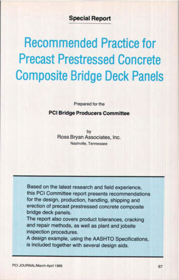
1.1 HistoryComposite deck panels are widelyused in the construction of bridges inthe United States. The 1986 survey conducted by PCI indicated that twentyone State Highway Departments andthree Turnpike Authorities havespecified the use of composite deckpanels.The panels were first used in the early195Os for construction of bridges on theIllinois TolIway. A number of statesbegan to use the panels in the late1960s and early 1970s. Also, several research projects were undertaken andcompleted during that time. 2-11 The results of that research along with earlierdesign experience form the basis forcurrent design practice.The earliest installations of deckpanels are nearing 35 years of age, andthe panels are performing well. 7 In morerecent years, isolated problems havebeen reported, especially cracking inthe composite top slab and excessivebowing of deck panels prior to installation. It was these concerns thatprompted the producer and user surveyand has resulted in this recommendedpractice report. These problems and therecommended solutions are discussedin this report.Additional historical information, references and photographs may be foundin the special state-of-the-art report,"Precast Prestressed Concrete BridgeDeck Panels," prepared by the PCICommittee on Bridges."1.2 MaterialsComposite bridge deck panels aretypically cast using low slump concretemixes. The use of water reducers andplasticizers are sometimes specified inorder to attain the required stress transfer and 28-clay strengths. Some agenciesspecify the use of rust or corrosion inPCI JOURNAUMarch-April 1988hibitors in the mixes; however, mostrely on the cast-in-place top slab to provide sufficient cover to prevent chloridepenetration into the composite deckpanels. Requirements for air entrainment in the composite deck panels vary.The types of aggregates used varywidely across the country. Aggregatesize should be no larger than 3/4 in, toensure that concrete is thoroughly consolidated below the strand in the shallow pan forms and to achieve concretestrengths specified.Strand used in deck panels includesnearly every size and type of strand produced. Trends now are toward the use of% in. diameter strand. The practice ofstrand use varies depending on considerations of strand development lengths.Typically, mild steel reinforcement isGrade 60 steel or welded wire fabric.1.3 AdvantagesCommon bridge deck constructionconsists of prestressed concrete girdersor steel girders supporting a roadwaydeck. This deck can be formed as a fulldepth cast-in-place slab or it can be constructed using precast prestressed composite bridge deck panels as shown inFig. 1.lithe bridge deck is cast in place forits full depth, forms must be installedand later removed. Forming costs arehigh and the installation and removal offorms is time consuming. In some situations this creates safety hazards to trafficunder the construction or to the workersthemselves. Stay-in-place metal formsare sometimes used. These also eliminate the need for form removal, butthey are subject to long term corrosionand do not replace or reduce the bottomreinforcement as they do not act compositely with the concrete slab.Precast prestressed concrete composite bridge deck panels eliminate theneed for most of this expensive forming73
CAST-IN-PLACE TOP SLABDECK PANELCAST-IN-PLACE TOP SLABpo- II. II 'DECK PANELFig. 1. Typical details of deck panels on prestressed girder(top) and steel girder.operation. The deck panel and cast-inplace top slab act compositely and resultin a significant material and cost savings. The prestressing strands in thedeck panels provide the necessary bottom reinforcement in the composite slabsystem. This eliminates the need for onelayer of mild steel reinforcement in thedeck. The deck panels are manufacturedwith dense, high strength concrete thatis more resistant to chloride penetration.Because the deck panels are prestressed, the designer has the ability tocontrol stresses in the important tensilestress zone.Composite bridge deck panels aremanufactured in established plantswhere proven production and qualitycontrol methods result in a productwhich conforms to specifications Mil74lions of square feet of precast prestressed concrete composite bridge deckpanels have been manufactured and instaIled. They have proven to be a soundeconomical alternative to conventionalforms and are usually chosen for construction when specifications permitalternate solutions.1.4 Design ConsiderationsThe design of precast prestressedconcrete composite bridge deck panelsmust include an analysis of the panelsfor stresses due to handling and duringconstruction as well as ultimate strengthof the composite section.Design drawings should show everyaspect of production and installation ofthe composite deck panels, including
storage instructions, bearing details, andall other special considerations.Shop drawings prepared by the fabricator must include all information contained on the design drawings as well asany special information necessary forproduction. Composite deck panellengths should be carefully selectedwith consideration given to tolerancesfor girder horizontal sweep in order toachieve proper bearing.When composite deck panels are usedon steel or prestressed concrete girders,the designer should recognize that shearstuds on steel girders and projectingstirrups on concrete girders must be lo-cated to minimize interference withcomposite deck panel placement.Torsional stresses are typically not induced in composite deck panels inbridges with straight girders. Torsion indeck panels due to girder movementshould be considered in the designwhen composite deck panels are usedon bridges with horizontally curvedsteel girders or box sections. These arespecial cases which should be carefullystudied.Stresses from differential movementof long, relatively flexible steel girdersshould also he evaluated by the bridgedesigner.CHAPTER 2- DESIGN2.1 General InformationThe design of precast prestressedconcrete composite bridge deck panelsis based on the requirements in theStandard Specifications for HighwayBridges published by the American As-sociation of State Highway and Transportation Officials (AASHTO).'As with prestressed concrete members in general, composite deck panelsare checked for transfer stresses, handling stresses, service load stresses, andfactored strength in shear and flexure.Research has shown that compositedeck panels as presently designed perform well under fatigue test conditions,and therefore no special provisions areneeded for fatigue. 2-6 Strand slippage isnot a common problem and tolerancesfor stressing forces as established byspecifying agencies are enforced.Although precast prestressed concretecomposite deck panels have been usedwith success for many years, concernsrelating to their production and use, aswell as differences between agenciesspecifying the products, have raisedsome questions. This chapter addressesthose questions and evaluates their efPCI JOURNALMarch-April 1988feet on design of the composite deckpanels.2.2 Panel Thickness and Size ofPrestressing StrandPanel thicknesses commonly used forcomposite deck panels have rangedfrom 2'/s to 4½ in. The panels should bemade as light as practicable for handlingpurposes, but this must be eva]uatedconsidering the potential for damage ifthe sections are too thin.The recommended minimum composite deck panel thickness for generaluse is 3 in. The panel thickness is animportant factor in choosing the size ofstrands to be used. The relationship ofpanel thickness to strand diametershould be approximately 8:1 as shownbelow. This has been reported to givevery satisfactory results.Panel Thickness Maximum strand size3 in.% in,3V2 in.The in.4 in. or larger½ in.The absolute minimum composite75
deck panel thickness should be 2½ in.Panels with this thickness, however, require special care during manufacturing, handling, and erection. With % in.strands, the resulting clear concretecover is 1'i in. Article 9.25.1.2.2 of theAASHTO specifications requires 1 in.minimum cover on prestressing strandsin the bottom of slabs. Full scale tests ofbridges with composite deck panels indicated that 1 in, of concrete cover onthe strands in the panels was adequate.,,Deviations from this recommendationare possible, but consideration must hegiven to the possibility of splitting of thepanel ends due to prestress transferforces. Use of thin panels or largestrands may require special end zonereinforcement, Deviations should besubmitted to the specifying agency forapproval.2.3 Strand LocationThe majority of composite deckpanels produced over the years havehad strands located at the centroid of thesection although eccentric prestressingcan result in significant cost savingsover concentric prestressing.Uniform spacing of the prestressingstrands is recommended to preventsplitting cracks in the panels.' Approximately equal strand patterns may beused where equally spaced strand patterns do not coincide with the compositedeck panel width or jacking headerspacing. "a2.4 Factored Moment Strength andStrand DevelopmentArticle 9.27 of the AASHTO Specifications provides a relationship fordetermining the development length ofprestressing strand:Development length:td (f – %f,)D(9 -3 2)where f ,, is the average stress in the pre76stressing steel at ultimate load.The term f also occurs in the equation for factored moment strength, Mu,.Article 9,17.2, Eq. (9-13). However, thevalue of J' may not always he the sameas applied to these two equations. Thereason for this is that when short lengthdeck panels are used, there may not heenough total length available to developthe full strength of the prestressingstrands.Article 9.17.4.2 states that the maximum value for f at ultimate load belimited to:f eu l %Df(9-19)where the term 1 r is the distance fromthe end of the prestressing strand to thecenter of the panel. In other words, astrand can develop a maximum value forf [Eq. (9-17) ] if the full developmentlength, 1 d , is available. When l ,x is lessthan l d , the maximum stress in thestrand will be correspondingly less.This will consequently reduce the valueof f,*, and the design flexural strength,M.This is demonstrated graphically inFig. 2. The prestressing reinforcementshown for this panel is insufficient for aspan of less than about 5 ft. This is because the allowable f has been significantly reduced due to the small value ofl. At a span length of just over 5 ft thereduction of f * is at its most criticalpoint, but as the span increases, theamount of the reduction becomes lesscritical because M„ is increasing muchfaster than the factored moment. For thisreason, in deck panels with longerspans, the formation of some splittingcracks or damage resulting from handling at the ends should not necessarilybe a cause for rejection. See the recommendations concerning cracks in Section 4.2.1.,This subject of reduced values for fv*„is illustrated in the design example inAppendix A:
40Additional reint.required due to 100% of aj used to calculateAASHTO equation9-19.length but panel has adequateflexural strength.drIon in 1 su by capacity because of embedment100% of f R used tocalculate flexuralstrength .30CIS : 1.0Topping Thickness : 4 in.Topping Strength At 28 Days : 4500 psiIaIzDesign FlexuralStrengthM„1Allowable Tension : 212 psi- Nominal Diameter Of Strand : 3/8 in.Deck Panel Thickness : 3 in.20M01-2 x Cra king Moment210 Factored Moment10DECK PANEL SIMPLE SPAN (FT.)Fig. 2. Moment capacity versus requirement with respect to span. 257 ksi [Eq. (9-17) unreducedvalue] 180 ksiD 0.375 in.Substituting these values into Eq.(9-32) gives:Development length, 1,: [257 – (%)(180)1(0.375) 50.1 in.fIn the design example, a reduction inmade from 257 to 243 ksi in compliance with Article 9.17.4.2. This reduction was a function of the distancefrom the end of the prestressing strandto the center of the panel (l x ). In order touse the full value off * to calculate design flexural strength, the developmentlength in this example must be 50.1 in.As can be seen, even when ** was reduced, the design flexural strength wasgreater than the actual required. Thisreveals that development length is notcritical for the majority of spans.Results of research on developmentlength vary substantially. Tests conaz wasfPCI JOURNAL March-April 1988ducted on different size strands haveshown that average developmentlengths of22 in. for % in. strands, and 34in. for '/a in. strands are required.'."Kluge recommends a 62 in. development length for 3 in. strands. Although many values are below, andsome are above, the AASHTO Specification requirements, the results are notconclusive enough to justify anyrecommended changes to these requirements.2.5 Panel Width and SpanComposite deck panels have beenfabricated with widths ranging from 2 ftto as much as 10 ft, with 4 and 8 ft beingthe most common.Decisions about panel width shouldinvolve discussions with the fabricatorand contractor concerning the advantages and disadvantages of wide versusnarrow composite deck panels. Widerpanels afford more effective use offorms. They also permit stripping and77
handling to proceed more rapidly because there are fewer pieces to handle.Preferred composite deck panelwidths are 4 and 8 ft. Two foot widepanels may he used at edges or wherenecessary due to bridge geometry.Trapezoidal or triangular pieces may beused at ends on skewed bridges.The composite deck panel spanlength is selected by the designer basedon girder spacing. Deck panel spans canvary and are influenced by deck panelthickness, cast-in-place slab thickness,superimposed loads, and required prestress force.2.6 Stress Transfer and 28-DayStrengthsArticle 9.22 of the AASIITO Specifications requires a minimum concretestrength at the time of stress transfer of4000 psi. Article 9.15 indicates designsare based on a 28-day minimum compressive strength of 5000 psi. Thesestrengths are routinely reached in panelproduction.2.7 Corrosion ProtectionCracks which form in the cast-in-placetop slab have not been observed to extend to the deck panels (see Section2.11). Research conducted by the TexasTransportation Institute' indicatedthese cracks did not occur in the testbridges until several months after const-action. The cracks most likely formeddue to shrinkage and thermal effects.Cores taken after ultimate load tests ofthe structure indicated the averagedepth of the cracks was approximatelyone-half the depth of the cast-in-placetop slat). Another study 2 also pointedout the importance of ensuring propercuring methods for the cast-in-placeslab.The use of corrosion inhibiting admixtures or epoxy coated reinforcementin the deck panels is generally notnecessary.782.8 FatigueResearch indicates cyclic loading upto 11 million cycles had no detrimentaleffect on the long term performance ofprecast prestressed concrete compositebridge deck panels.2,3,,, anSpecial attention is therefore not required in the design of composite deckpanels for fatigue, However, cyclicloading should be considered in reviewing details for permanent bearings.Proven systems such as those describedin Section 2.10 should be used.2.9 Strand ProjectionsResearch indicates that the overallbehavior of bridges with and withoutdeck panel strand projections is verynearly the same. a," The most importantfactor is adequate bearing for the panelson the bridge girders. The use of strandprojections is not an acceptable substitute for good bearings. In many cases,strand projections contribute a substantial cost component by inhibitingthe production of deck panels by longline casting and saw cutting. Therefore,it is recommended they not be used.2.10 Bearing Systems2.10.1 GeneralOne of the most important components of a bridge constructed using prestressed composite deck panels is bearing of the deck panel on the bridgegirder.Composite bridge deck panels mustbe supported on the bridge girders by apermanent bearing material providingcontinuous and solid support and consisting of mortar, grout, concrete orsteel. 6 Research conducted on bridges inFlorida, 15.t which used only a soft fibrous material as the final bearing underthe ends of the deck panels, indicated:(a) The overall bridge deck behavedmore like simple spans than acontinuous slab over the stringers.(b) The ends of the composite deck
Fig, 3. Dimensions of temporary bearings for supporting deck panels.panels delaminated from thecast-in-place topping, forcing thetopping alone to carry the liveload shear.(c) The majority of these bridges developed extensive cracking.Bridges with this hearing detailwill have a reduced service life.?2.10.2 Temporary BearingIi grout or concrete is used as permanent bearing material, the compositedeck panels must he supported abovethe bridge girders by a temporary bearing system. The temporary bearing system provides support for the panels during erection and until the grout or concrete reaches design strength. The temporary bearing system may be designedto be removed or may remain in place.Removable systems include woodPCI JOURNALJMarch-April 1988planks and steel angles or channels attached to the sides of the bridge girders.These supports are removed after thecast-in-place top slab reaches designstrength.Temporary systems designed to remain in place include continuous stripsof compressible material such as expanded polystyrene, fiberboard, orbituminous fiberboard, Unyieldingmaterials such as steel or hard plasticshims, which are left in place aftergrouting, will continue to provide theprimary support for deck panels shouldthe permanent grout or concrete bearingmaterial shrink. This will result inundesirable cracking in the bridge deckslab over these rigid bearing points.Therefore, temporary bearing materialswhich are designed to remain in placemust be compressible.79
Proper performance of the finisheddeck requires that the height of the temporary bearing material he adequate toallow grout or concrete to flow easilyunder the deck panel overhang. Thisshould be a minimum of I in. whengrout is used. The vertical clearanceshould be increased to a minimum of 11/zin. if the top slab concrete is to flowunder the deck panels to provide permanent support (see Fig. 3). The tops ofsupporting girders must be smoothenough to allow the grout or concrete toflow readily. The composite deck panelsmust extend a minimum of 1 1/2 in. beyond the temporary bearing material.Compressible bearing materials willindeed be compressed due to the weightof the deck panel. This decrease invertical clearance must be accounted forin sizing the temporary bearings.2.10.3 Permanent BearingWhen composite deck panels werefirst used, they were supported on continuous hand placed mortar beds. Thismethod of support works well and is stillwidely used. The mortar bed should bea minimum of 1 in, thick and 3 in. wide.The thickness can be controlled byusing small wooden or plastic pegs cutto the proper length acting as spacers.The spacers must be retrieved beforesetting deck panels so as not to providepermanent support when the mortarshrinks. Deck panels must he placed onthe mortar beds before the mortar hardens to ensure they have even support.The use of grout, concrete, and mortarbeds for permanent hearings have beentested and found to perform satisfactorily through as many as two million applications of simulated design axle loadwith impact.2 59 7When flowable grout or concrete isused, venting is required to ensure thatfinal placement is not inhibited by airlock. This should be accomplished byleaving small gaps in the strips of compressible bearing material at a spacing80of approximately 36 in.If grout is used as the permanentbearing material, it should he a highstrength, low slump cementitious groutor a nonshrink grout with a maximumcompressive strength of 5000 psi. Thestrength of the grout should be verifiedby tests prior to placement of the castin-place top slab.If the top slab concrete is designed toflow under the composite deck panel forpermanent support, proper placementprocedures should be followed. Concrete should he deposited in continuousstrips over the girders and allowed toflow under the ends of the compositedeck panels. Concrete should then beplaced on the remainder of the panels.This procedure improves the flow ofconcrete under the panel ends, helpseliminate air pockets, and places concrete under the panels before the compressible temporary bearings are loadedwith the weight of the fresh concrete.2.10.4 Installation ProfileThe contour of the roadway surfaceusually does not follow the top surfacesof the girder. This is due to girdercamber, vertical curvature of the structure, superelevation of the roadway, or acombination of these. To account forelevation variations, there are two options to consider for support of the co
Precast and prestressed concrete composite bridge deck panels are used with cast-in-place concrete to provide a convenient and cost effective method of construction for concrete bridge decks. The panels are usually precast at a manufacturing plant. They are trucked to the bridge construction site and lifted b