Transcription
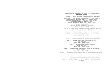
How to build a Simplified Arduino CW Trainer by Tom N4TLSeptember 16, 2016 version 2.1 (see the last page for V2 information)The September 2016 issue of QST has my original article about the Arduino CW trainer.That article does not have too much information on how to build the trainer. More information is in this paper. Figure one shows the original CW trainer, figure two shows asimplified version. The simplified version is easier to build because it does not have arelay output or a connection for a nine volt battery through a switch. Both are not needed for the trainer. The speaker will provide the audio output. The power is supplied byContinued on page 3Schematic of the original Arduino CW Trainer.1
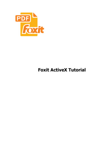
Nine voltpowerconnectorSchematic of the simplified Arduino CW Trainer.Figure 3, Nine Volt Power Adapter, PID 63Figure 4, Nine Volt Battery Case, PID 672
an AC adapter or an external nine volt battery. Adafruit has a nine volt battery case witha plug that will plug in to the Arduino power connector. They also sell an AC adapterthat can be used. See Figures 3 and 4 for pictures of them. When searching for parts atthe adafruit website, enter the product number in their search box without a pid in frontof it. I have no connection to adafruit. You can buy parts anywhere but my LCD codeworks with the adafruit LCD display and may not work with other displays. I have Hyperlinks for many of the parts in this document. To open a Hyperlink just click on theblue underlined text.Figure 5, New Arduino pid 50 powered by a nine volt battery in a caseFigure five shows a nine volt battery in a case powering a brand new Arduino. Onegreen LED is on and one yellow one is blinking. The brand new Arduinos are programed to blink the yellow LED.Here is an easier to read parts list for the Simplified CW Trainer.BT1 Power can be supplied by either of these.Nine Volt Power Adapter, adafruit PID 63.Nine Volt Battery Case, adafruit PID 67.J2 PS2 Keyboard connector adafruit pid 804.J3 RCA connector, for keying input.LS1 Speaker, adafruit pid 1890.S2 Momentary push button switch for reset.U1 Arduino adafruit pid 50.U2 RGB LCD Shield with a 16x2 character display, adafruit PID 714.U3 Proto Shield kit, adafruit, PID 2077. PS2 keyboard. Keyer and paddle. A straight key can be used but it is better to learnhow to use a paddle and Keyer. The Keyer needs to have a side tone.3
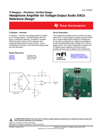
I used a clear plastic Lustroware 13 oz. food container to hold the completed CW Trainer.The food container was the right size for the project and it was easy to drill holes in it. Ibought it at The Container Store here in Raleigh.U2, RGB LCDShield with a16x2 characterdisplayLS1, SpeakerLS1 SpeakerJ2, PS2 KeyboardU3, Proto Shield kitJ3, RCA connectorS2, Resetpush buttonU1, ArduinoNine volt powerconnectorFigure 6, The three circuit boards that make the Arduino CW Trainer.Figure 6 shows the three circuit boards that make the Arduino CW Trainer. J1 and S1 arenot used.4
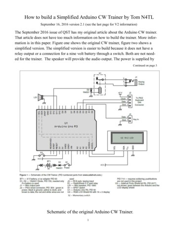
Figure 7, The three circuit boards connected to each other and turned on.Figure 8, Side view of the Arduino CW TrainerThe two white wires from the trainer to the speaker don’t show up very well. Morepictures are on the following pages.5
Here is more information on the Proto Shield kit. It provides places to connect theconnectors, switch and speaker.Figure 9, adafruit Proto Shield kit, PID 2077.Figure nine show the parts that come with the Proto Shield kit, adafruit PID 2077. All theparts are not needed for this project. For information on how to assemble it, go to the adafruit website. On the 2077 product page, slide down to where it says, “Comes as a kit ofparts so you can choose how you want to configure your shield. However its ver yeasy to assemble even for beginning solderers. More information & instructions are available here. “. Click on More information and down load the PDF file. Read the documentand install the stacking headers. Do not use the plain headers shown on page 22 of thedocument. Install the stacking headers and the two small capacitors. After that follow thepictures on the next few pages.Figure 10, adafruit Proto Shield kit with the stacking headers and two capacitors installed6
Now add the speaker and PS2 Keyboard connector.Figure 11, adafruit keyboard connector pid 804 and speaker pid 1890Figure 12, Close up of the keyboard connector wiring and speaker wiringFigure 13, keyboard connector and speaker connected.The red and white wires on the PS2 connector are not used.7
PS/2 keyboardconnectorSpeakerRCA for keying inputMomentary pushbutton for resetFigure 14, This picture shows the reset pushbutton and the keying input addedFigure 15, close up of the shield in figure 14Figure 15 shows the completed Proto shield for the simplified version of the CW Trainer.8
Figure 16 shows an assembled RGB LCD Shield with a 16x2 character display. The adafruit website shows the display, PID 714 as a RGB LCD Shield Kit w/ 16x2 Character Display - Only 2 pins used! -. It really uses four pins, two for signals, one for power and onefor ground. Assembly instructions for the display are at the adafruit website. After it is assembled and turned on don’t forget to adjust the contrast. On mine I did not see anythinguntil the contrast was adjusted.Figure 16, RGB LCD Shield with a 16x2 character display, adafruit PID 714.All the parts that make this RGB LCD shield are shown on the next page.9
Figure 17, I2C controller and keypad shield kit for 16x2 LCD (PID 715).Figure 18, RGB LCD 16X2 (PID 399)10
My Parts CostsParts cost at adafruit.July ---------------1 x 9 VDC 1000mA regulated switching power adapter - UL listed[ID:63] 6.951 x PS/2 Wired Connector - Panel Mount MiniDIN-6[ID:804] 3.951 x Arduino Uno R3 (Atmega328 - assembled)[ID:50] 24.951 x RGB LCD Shield Kit w/ 16x2 Character Display - Only 2 pins used! (NEGATIVEDISPLAY) [ID:714] 24.951 x Adafruit Proto Shield for Arduino Kit - Stackable Version R3[ID:2077] -------Sub-Total: 70.75United Parcel Service (1 pkg x 0.98 lbs total) (UPS GROUND): 8.55Sales Tax: 0.00Total: 79.30I already had a Speaker, adafruit pid 1890 ( 1.50) and did not buy another one. I alsohad a momentary push button for the reset and a RCA jack for the keying input.Other builders Parts CostsOne person that I have been exchanging emails with has built the CW Trainer for lessthen 10.00. Here are two links he sent me. He had to change the LCD code so it wouldwork with this her person told me about this uino-scm-supplies-436Another person's input.Digikey stocks the PS/2 connector for 2.47. They will ship via US Mail for a lot lessthan Adafruit. Digi-Key Part Number CP-2960-ND.I am sure there are many more places to buy parts.11
Programming the ArduinoYou will need to program the Arduino with the trainer sketch (program). First you willneed the Arduino Development Environment (ADE) on your home computer. Chapterfive of the book ARRL book Arduino for Ham Radio has information about it. This website also has information, https://www.arduino.cc/en/Guide/Environment.Here is the sketch and the libraries you will need.The source code for the Trainer is on the ARRL website. Go to http://www.arrl.org/qst-in-depth and look for the September issue and Trainer Sketch.The LCD library from the adafruit website s.The MorseEnDecoder library found at http://www.w5obm.us/Arduino/. Go to chapter 22and MorseEnDecoder. Copy the files MorseEnDecoder.cpp, MorseEnDecoder.h and keywords.txt to your Arduino libraries.C:\Program Files (x86)\Arduino\libraries\MorseEnDecoder\You will get an error when you compile the pr ogr am that reads like der.cpp:69:19: error: variable'morseTable' must be constin order to be put into read-only section by means of ' attribute ((progmem))'char morseTable[] PROGMEM "*5*H*4*S***V*3*I***F***U?* **2*E*&*L\"**R* .****A***P@**W***J'1* *6-B* *D*/" exit status 1Error compiling for board Arduino/Genuino Uno.To fix this error, edit the Mor seEnDecoder.cpp file and add const to line that star tswith char morseTable[].Here is the corrected line.const char morseTable[] PROGMEM "*5*H*4*S***V*3*I***F***U?* **2*E*&*L\"**R* .****A***P@**W***J'1* *6-B* *D*/"12
The Morse Library is at http://www.w5obm.us/Arduino/ go to chapter 7 and then Morse. Icopied all the files keyworks.txt, Morse.cpp, Morse.h and a directory of Examples to my system. The directory is C:\Program Files (x86)\Arduino\libraries\Morse.The PS2 keyboard library can be found at http://www.w5obm.us/Arduino/ go to chapter 19.Then PS2Keyboard and then copy the PS2Keyboard.cpp, PS2Keyboard.h and keywords.txt.Copy them to your Arduino libraries,C:\Program Files (x86)\Arduino\libraries\PS2Keyboard.This PS2Keyboard library was modified to add F1-F12 keys and other minorcorrections by Glen Popiel - KW5GPOnce you have all the items on your computer you can use the ADE to program the Arduinovia the computer’s and Arduino USB ports.Adafruit PS/2 keyboard connector information. Green wire is 5VBlack wire is GroundBrown wire is Data, goes to pin D5 on Arduino.Yellow wire is Clock, goes to pin D3 on Arduino.White wire is sometimes Mouse Data for 2-in-1 splitter cables, not used.Red wire is sometimes Mouse Clock for 2-in-1 splitter cables, not used.I tried a USB keyboard on this project by buying a USB to PS2 adapter at OfficeDepot. It will convert a USB keyboard to a PS2 connector. It did not work.13
PS/2 KeyboardKeyerPS/2 keyboardconnected to J2Power inFrom theKeyer’s outputConnected to J3Bencher KeyArduino CW TrainerCode practice oscillatorThis picture shows the whole setup. The keyboard at the top is connected to the trainer withthe purple connector. A USB keyboard will not work. The Bencher key is connected to theKeyer on the top right of the shelf. The Keyer does not have a speaker for a side tone, so it isconnected to a code practice oscillator just below it in the black box. The output of the Keyeris also connected to the Arduino CW Trainer. If my Keyer had a side tone oscillator built inthe Code Practice Oscillator would not be needed.The relay output J1 is not used. It is not needed. I had it in my original design because I wasalso experimenting with a Arduino Keyer.I connected my straight key to the input of the Arduino CW Trainer and the Trainer was ableto decode my sending. I did not even have to change the speed in the trainer for the slowersending14
This is a list of keys on the keyboard that are used by the Arduino CW Trainer Sketch. The Up arrow increases the sending speed. The down arrow decreases sending speed. The Right arrow increases the number of characters sent before the Arduino checks for incomingcharacters sent by the student. The Left arrow decrease the number of characters sent before the Arduino checks for incoming characters sent by the student. F1, Sets the character set to the twenty six letters of the alphabet. F2, Sets the character set to the ten numbers. F3, Sets the character set to these four characters, period, comma, slash and question mark. F4, Sets the character set to all forty characters listed above. F5, Kotch method. Enter a one or two digit number followed by the enter key. F6, Kotch method with different starting point. Enter a one or two digit number followed by the enterkey. Use F5 before using F6. F7, Set a delay from 0 to 30 to slow down sending. Version 2 of the sketch. F9, is used to toggle between the internal speaker or relay output. Do not use if your trainer does nothave the relay output. F10, saves the parameters in to the Arduino’s EEPROM. F10 has to be pushed before the G is enteredto start the code generation. The next time the trainer is used, the parameters will be read from theEEPROM. The user only has to push G to continue. G, short for go. It starts the Arduino sending code via the speaker or relay. D, for decoder. It runs the CW decoder only. The speaker is not used. P, for checking the sending speed, PARIS is sent until reset is pushed. V ersion 2 of 53637383940B?427C1D6X15
Using the Arduino CW TrainerLearn to send.The first thing to do is learn how to send so that the trainer can copy your code.Turn on the trainer and push D. That will run the decoder only. Now send to thetrainer. Make sure your sending can be copied by the trainer. I found that I need toleave a little more space between each character.Learn the sounds.Now use the Kotch method to learn the sound of each character. Push F5 followedby a 1. Push the right and left arrows so that you have 2 characters selected. Thenpush F10 to save the values. Now push G for go. The trainer will send you K andK. You send K and K back. After you know the sound of K push reset. Now pushF5 followed by a 2. Now push F10 and G. The trainer will send you K and M.Now send K and M back with out looking at the display so that you learn thesounds. Keep doing this with more and more characters until you know all ofthem. You can use F6 to set a different starting point in the Kotch method.Work on remembering what was sent.Now change the number of characters sent from 2 to higher numbers, and practiceremembering what was sent, again with out looking at the display and not writinganything down.If you stop one day and come back the next day the trainer will remember whereyou left off because you pushed F10. If you want to continue where you were theday before all you have to do is push G.As I said in the article I am not an expert on learning the code. Jack W0UCE (SK)was. Do a google search on “W0UCE's method for teaching CW” and read whathe wrote. Also look at ing-morse-code.73 Tom, N4TL16
September 16, 2016, Version 2.1I updated the sketch after receiving feedback from some users.Added F7, This is used slow down sending by putting a delay between characters. Zero to30 can be entered. Each count is 0.01 seconds. I found a number of 10 to 20 will slow thesending down okay. This delay allows the characters to be sent a full speed with delay between each character. This is called the Farnsworth method. So now you can use theKoch and Farnsworth methods at the same time.Added P to the keyboard control. When P is pushed the trainer will send PARIS over andover again until reset is pushed The length of time it takes to send PARIS divided in to 60gives the speed in WPM. I changed the Key speed adj -2 and measured these speeds. Idon’t know if different processor speeds will change these speeds.Trainer speedMeasured speedF7 delay 0Measured speedF7 delay 10Measured speedF7 delay ed D, when characters are written to a new line, it is blanked first instead of beingoverwritten. The characters are also written to the serial monitor.One bug was fixed. Up to 10 characters are stored and compared to the student's sending.The right arrow routine allowed up to 15. This was changed to 10. I did some code cleanup and added a few constants. When the trainer first starts, I added a period after N4TL.That allows me to know I am running the second version.I may write another sketch that will send short words. If I do I will put information aboutit on QRZ under my call’s information, and at QSL net, www.qsl.net/n4tl.If you build a Arduino CW Trainer please let me know by sending me your name and callvia email, n4tl2 at yahoo.com, thanks.73 Tom N4TL17
Figure 5, New Arduino pid 50 powered by a nine volt battery in a case Here is an easier to read parts list for the Simplified CW Trainer. BT1 Power can be supplied by either of these. Nine Volt Power Adapter, adafruit PID 63. Nine Volt Battery Case, adafruit PID 67. J2 PS2 Keyboard connector adafruit pid 804. J3 RCA connector, for keying input.