Transcription
ATTACHMENT BDesign ExamplesThe following five design examples illustrate the use of the design guide specifications prepared in thisproject and subsequently published by AASHTO (AASHTO Guide Specifications, 2018):Example B-1: Design of a rectangular beam pretensioned with straight CFRP cablesExample B-2: Design of a Decked AASHTO pretensioned girder with straight CFRP cablesExample B-3: Design of a Decked AASHTO pretensioned girder with harped CFRP cablesExample B-4: Design of a rectangular beam post-tensioned with straight CFRP cablesExample B-5: Design of a Decked AASHTO post-tensioned girder with draped CFRP cablesREFERENCESAASHTO-LRFD (2017). AASHTO LRFD Bridge Design Specifications, 8th edition, Washington, DC,USA.AASHTO Guide Specifications (2018). Guide Specifications for the Design of Concrete Bridge BeamsPrestressed with Carbon Fiber-Reinforced Polymer (CFRP) Systems, 1st edition, Washington, DC, USA.Adil, M., Adnan, M., Hueste, M., and Keating, P. (2007). Impact of LRFD Specifications on Design ofTexas Bridges Volume 2: Prestressed Concrete Bridge Girder Design Examples.Bridge Design Manual (2014). Precast/Prestressed Concrete Institute (PCI), Chicago, IL.Cousins, T. E., Roberts-Wollmann, C. L., and Brown, M. C. (2013). “NCHRP Report 733: Highperformance/high-strength lightweight concrete for bridge girders and decks." Transportation ResearchBoard of the National Academies, Washington, DC.Wassef, W., Smith, C., Clancy, C., and Smith, M. (2003). Comprehensive design example for prestressedconcrete (PSC) girder superstructure bridge with commentary. Federal Highway Administration report no.FHWA NHI-04-043, grant no. DTFH61-02-D-63006. Washington, DC.
Example B-1: Design of a rectangular beam pretensioned with straight CFRP cablesThe following example illustrates the analysis of rectangular beam pretensioned with two prestressingcables of 0.6 inch diameter and a jacking stress of 0.70 fpu . The beam is 31 ft in length and carries akipsuperimposed dead load of 20% of it's self-weight and the live load of 0.35 ――in addition to its ownftweight. The analysis includes checking all applicable service and strength limit states according toAASHTO-LRFD (2017) and AASHTO Guide Specifications (2018). They are referred in the followingexample as AASHTO and AASHTO-CFRP respectively. The analysis also includes the computations ofdeflection corresponding to the moment of 130.0 ft·kip .Overall beam LengthLspan 31 ftDesign SpanLdesign 30 ftConcrete PropertiesConcrete strength at release,f'ci 5.5 ksiConcrete strength at 28 days,f'c 9.0 ksiUnit weight of concreteγc 150 pcfPrestressing CFRPDiameter of one prestressing CFRP cabledb 0.6 inArea of one prestressing CFRP cableApf 0.18 in 2B1- 1
The design tensile load is the characteristics value of the tensile test data conducted as a part ofNCHRP 12-97 project and computed according to ASTM D7290 as recommended by the proposedmaterial guide specification. The design tensile stress is obtained as follows:Design tensile stress64.14 kipfpu ――― 356.33 ksiApfModulus of elasticity (AASHTO-CFRP Art. 1.4.1.3)Ef 22500 ksiDesign tensile strainfpu 0.016εpu ―EfStress limitation for prestressing CFRP (AASHTO-CFRP Art. 1.9.1)Before transferfpi 0.70 fpu 249.43 ksiAt service, after all lossesfpe 0.65 fpu 231.62 ksiNonprestressed Reinforcement:Yield strengthfy 60 ksiModulus of elasticity (AASHTO Art. 5.4.3.2)Es 29000 ksiBeam Section PropertiesWidth of beamb 12 inHeight of beamh 20 inCross-section area of beamA b h 240 in 2Distance from centroid to the extreme bottom fiber ofthe non-composite precast girderh 10 inyb ―2Distance from centroid to the extreme top fiber of thenon-composite precast girderyt h - yb 10 inSection modulus referenced to the extreme bottom fiber ofthe non-composite precast girderb h3I ―― 8 10 3 in 412ISc ― 800 in 3ybSection modulus referenced to the extreme top fiber of thenon-composite precast girderISct ― 800 in 3ytMoment of inertia of deck about it centriodB1- 2
kipw (b h) γc 0.25 ――ftWeight of the beamMaterial Properties for Girder and Deck Concrete:At release γc 2.0 f'c 0.33E f'c 12 ―― ― psi pcf psi Eci E f'ci 4.63 10 3 ksiAt 28 days (Girder)Ec E f'c 5.45 10 3 ksiModulus of rupture of concrete (AASHTO Art 5.4.2.6)fmr f'c 0.24 At releasefri fmr f'ci 0.56 ksiAt 28 days (Girder)fr fmr f'c 0.72 ksiModulus of elasticity of concrete (AASHTO Art. 5.4.2.4)‾‾‾f'c― ksiksiNumber of Strands and Strand Arrangement:Total number of prestressing CFRPnp 2Concrete covercc 2.75 inDepth of prestressing CFRP from the top fiber ofthe beamdp h - cc 17.25 inEccentricity of prestressing CFRPec dp - yt 7.25 inLoad and Moment on Beam:kipwSD 0.2 w 0.05 ――ftkipwL 0.35 ――ftUnit weight due to superimposed loadUnit weight due to live loadMb unfactored bending moment due to beam self-weight, k-ftw Ldesign 2Mb ―――― 28.13 ft·kip8MSD unfactored bending moment due to superimposed deadload, k-ftwSD Ldesign 2 5.63 ft·kipMSD ――――8B1- 3
ML unfactored bending moment due to live load, k-ftwL Ldesign 2ML ―――― 39.38 ft·kip8Moment at service III [AASHTO Table 3.4.1-1]Ms Mb MSD 0.8 ML 65.25 ft kipMoment at Strength I [AASHTO Table 3.4.1-1]Mu 1.25 Mb 1.5 MSD 1.75 ML 112.5 ft kipPrestressing LossPrestressing CFRP stress before transferfpi 0.70 fpu 249.43 ksiElastic ShorteningEf fcgpΔfpES ―Ect[AASHTO-CFRP Eq. (1.9.2.2.3a-1)]Where Ef modulus of elasticity of prestressing CFRP (ksi)Ect modulus of elasticity of the concrete at transfer or time of load application(ksi) Ecifcgp the concrete stress at the center of gravity of CFRP due to the prestressingforce immediately after transfer and the self-weight of the member at sections ofmaximum moment (ksi)AASHTO Article C5.9.5.2.3a states that to calculate the prestress after transfer, an initialestimate of prestress loss is assumed and iterated until acceptable accuracy is achieved. In thisexample, an initial estimate of 10% is assumed.eloss 10%Force per strand at transferPi Pi ec 2MG ec ―――- ―――fcgp ―AgIgIgWhere,Pi total prestressing force at release np * pec eccentricity of strands measured from the center of gravity of the precast beamat midspanB1- 4
MG moment due to beam self-weight at midspan (should be calculated using theoverall beam length)w Lspan 2MG ――― 30.03 ft·kip8eloss 10% np Apf fpi (1 - eloss) np Apf fpi (1 - eloss) ec 2EfMG e c eloss ―― ――――――― ―――――――――- ――― fpi Eci AII eloss find (eloss) 0.01Therefore, the loss due to elastic shortening eloss 0.01The stress at transfer fpt fpi (1 - eloss) 246.39 ksiThe force per strand at transfer pt Apf fpi (1 - eloss) 44.35 kipThe concrete stress due to prestress np pt np pt ec 2Mb ec 646.53 psifcgp ―― ――― - ――AIIThe prestress loss due to elastic shortening Total prestressing force at releaseEfΔfpES ― fcgp 3.14 ksiEciPt np pt 88.7 kipFinal prestressing loss including Elastic ShorteningAssume a total prestress loss of 18% [This assumption is based on the average of all cases in the designspace considered in the reliability study]ploss 18%fpe fpi (1 - ploss) 204.54 ksiForce per strand at servicepe fpe Apf 36.82 kipCheck prestressing stress limit at service limit state:B1- 5[AASHTO-CFRP Table 1.9.1-1]
if fpe 0.6 fpu “Stress limit satisfied”‖ “Stress limit satisfied”‖else‖ “Stress limit not satisfied”‖Check Stress at Transfer and Service:Stresses at TransferTotal prestressing force after transferPt np pt 88.7 kipStress Limits for ConcreteCompression Limit:[AASHTO Art. 5.9.2.3.1a]0.6 f'ci 3.3 ksiWhere, f'ci concrete strength at release 5.5 ksiTension Limit:[AASHTO Art. 5.9.2.3.1b]Without bonded reinforcement-0.0948 ‾‾‾f'ci― ksi -0.22 ksiksi -0.2 ksiTherefore, tension limit, -0.2 ksiWith bonded reinforcement (reinforcing bars or prestressing steel) sufficient to resist thetensile force in the concrete computed assuming an uncracked section where reinforcementis proportioned using a stress of 0.5 fy , not to exceed 30 ksi.-0.24 ‾‾‾f'ci― ksi -0.56 ksiksiIf the tensile stress is between these two limits, the tensile force at the location being consideredmust be computed following the procedure in AASHTO Art. C5.9.4.1.2. The required area ofreinforcement is computed by dividing tensile force by the permitted stress in the reinforcement(0.5 fy 30 ksi)Stresses at Transfer Length SectionStresses at this location need only be checked at release since this stage almost alwaysgoverns. Also, losses with time will reduce the concrete stresses making them lesscritical.B1- 6
Transfer lengthfpi dblt ―――αt f'ci 0.67[AASHTO-CFRP Eq. 1.9.3.2.1-1]Where, db prestressing CFRP diameter (in.)αt coefficient related to transfer length taken as 1.3 for cableAlso can be estimated aslt 50 db 30 inMoment due to self-weight of the beam at transfer lengthMbt 0.5 w lt Ldesign - lt 8.59 ft kipStress in the top of beam:Pt Pt ec Mbt- ―― ―― -0.31 ksift ―ASctSctTensile stress limits for concrete -0.2 ksi without bonded reinforcement[NOT OK]-0.56 ksi with bonded reinforcement[OK]stress in the bottom of the beam:Pt Pt ec Mbt ――- ―― 1.04 ksifb ―AScScCompressive stress limit for concrete 3.3 ksi[OK]Stresses at midspanStress in the top of beam:Pt Pt e c M bft ―- ―― ―― -0.01 ksiASctSctTensile stress limits for concrete -0.2 ksi without bonded reinforcement[NOT OK]-0.56 ksi with bonded reinforcement[OK]B1- 7
stress in the bottom of the beam:Pt Pt ec Mbfb ― ――- ―― 0.75 ksiAScScCompressive stress limit for concrete 3.3 ksi[OK]Stresses at Service LoadsTotal prestressing force after all lossesPe np pe 73.63 kip[AASHTO Art. 5.9.2.3.2a]Concrete Stress Limits:Due to the sum of effective prestress and permanent loads (i.e. beam self-weight, weight offuture wearing surface, and weight of barriers) for the Load Combination Service 1:for precast beam0.45 f'c 4.05 ksiDue to the sum of effective prestress, permanent loads, and transient loads as well as duringshipping and handling for the Load Combination Service 1:0.60 f'c 5.4 ksifor precast beamTension Limit:[AASHTO Art. 5.9.2.3.2b]For components with bonded prestressing tendons or reinforcement that are subjected tonot worse than moderate corrosion conditions for Load Combination Service IIIfor precast beam-0.19 ‾‾‾f'c― ksi -0.57 ksiksiStresses at MidspanConcrete stress at top fiber of the beamTo check top stresses, two cases are checked:Under permanent loads, Service I:Pe Pe ec Mb MSD- ―― ――― 0.15 ksiftg ―ASctSctB1- 8 4.05 ksi[OK]
Under permanent and transient loads, Service I:MLftg ftg ―― 0.74 ksiSct 5.4 ksi[OK]Concrete stress at bottom fiber of beam under permanent and transient loads, Service III:Pe Pe ec Mb MSD (0.8) ML fb ― ――- ――――――― -4.65 10 -3 ksiAScSc -0.57 ksi[OK]If the tensile stress is between these two limits, the tensile force at the location being consideredmust be computed following the procedure in AASHTO Art. C5.9.2.3.1b. The required area ofreinforcement is computed by dividing tensile force by the permitted stress in the reinforcement(0.5 fy 30 ksi)Stregth Limit Statefpe 9.09 10 -3εpe ―EfEffective prestressing strainIf εcc 0.003 , the stress block factors are given by f'c -3εco ―― 1.6 10 0.002411ksi εcc 4 - ― εco f'c β1 εcc , εco max 0.65 , ―――― - ―― 1.1 εcc 50 ksi 6 - 2 ― εco εcc 1 εcc 2 ― ― - ― εco 3 εco f'c α1 εcc , εco ―――――― - ―― 1 β1 εcc , εco 60 ksi B1- 9[AASHTO-CFRP Eq. C1.7.2.1-3][AASHTO-CFRP Eq. C1.7.2.1-4]
By using equillibrium and compatibility, the depth of the neutral axis (c) and the strainat top fiber of the beam can be found using followingc 8 indp 17.25 inεcc 0.0015εco 0.0024εpu 0.0158εcc 0.003dp - c εcc εpuεpe ――c dp - cα1 εcc , εco f'c β1 εcc , εco b c np Apf Ef εpe ―― εcc c 0.2482 ft find c , εcc 0.0014 cc c εεcc 0.0014 εcc 4 - ― εco f'c β1 max 0.65 , ―――― - ―― 1.1 0.65 εcc 50 ksi 6 - 2 ― εco εcc 1 εcc 2 ― ― - ― εco 3 εco f'c α1 ―――――― - ―― 1 0.61β1 60 ksi Depth of neutral axis,c 2.98 inStrain at prestressing CFRP at ultimatedp - c εcc 0.0067εf ――cTotal tension forceTf np Apf Ef εf εpe 128.28 kipTotal compression forceCc α1 f'c β1 b c 128.28 kipCheck for equillibriumTf - Cc 2.54 10 -12 kipThe capacity of the section is:B1- 10
β1 c Mn Tf dp - c Cc c - ―― 174.05 ft·kip2 Selection of strength resistance factor:ϕ 0.75[for CFRP prestressed beams ]Check for capacity[AASHTO-CFRP Art. 1.5.3.2]ϕ Mn 130.54 ft kipMu 112.5 ft kipif ϕ Mn Mu “Section capacity is adequate”‖ “Section capacity is adequate”‖else‖ “Section capacity is NOT adequate”‖Minimum ReinforcementThere is a on-going NCHRP project for revising the minimum reinforcement provisions forprestressed beams. Therefore, the outcome of the NCHRP 12-94 may also influence therequirements for CFRP prestressed beams.At any section of a flexural component, the amount of prestressed and nonprestressed tensilereinforcement shall be adequate to develop a factored flexural resistance, Mr, at least equal tothe lesser of:1.33 times the factored moment required by the applicable strength load combinations ScMcr γ3 γ1 fr γ2 fcpe Sc - Mdnc ― - 1 Snc [AASHTO-CFRP 1.7.3.3.1-1]Where, γ1 1.6 flexural cracking variability factorγ2 1.1 prestress variability factorγ3 1.0 prestressed concrete structuresγ1 1.6γ2 1.1γ3 1.0Pe Pe e c M b ――- ―― 0.55 ksifcpe ―AScScfr 0.20 Mcr γ3 γ1 fr γ2 fcpe Sc 104.5 ft kipB1- 11‾‾‾f'c― ksi 0.6 ksiksi
Check for governing moment:govmoment if Mcr 1.33 Mu 104.5 (ft kip)‖M‖ crelse‖ 1.33 Mu‖Check for minimum reinforcement requirementif govmoment ϕ Mn “Minimum reinf. requirement OK”‖ “Minimum reinf. requirement OK”‖else‖ “Minimum reinf. requirement NOT OK”‖Deflection and Camber[Upward deflection is negative]Deflection due to Prestressing Force at Transfer-Pt ec Lspan 2 -0.3 inΔpt ――――――Eci I8Deflection due to Beam Self-Weight5 w Lspan 4Δb ―――――384 Eci IDeflection due to beam self-weight at transfer:5 w Lspan 4Δbt ――――― 0.14 in384 Eci IDeflection due to beam self-weight used to compute deflection at erection:5 w Ldesign 4Δbe ――――― 0.12 in384 Eci IDeflection due to Superimposed Dead Load45 wSD Ldesign 0.02 inΔSD ―――――384 Ec IDeflection due to Live Load5 wL Ldesign 4 0.15 inΔL ―――――384 Ec IB1- 12
Using ACI 440 multipliers for long-term deflectionsImmidiate camber at transferδt Δpt Δbt -0.16 inCamber at erectionδe 1.80 Δpt 1.85 Δbt -0.28 inδf 1 Δpt 2.70 Δbt 4.10 ΔSD ΔL 0.31 inDeflection at finalDeflection due to Live Load when the Section is Cracked (i.e, for an moment of 160 ft-kip)Stress at bottom fiber due to the effect of prestress onlyPe Pe e cfcpe ― ―― 0.97 ksiAScTensile strength of concretefr 0.24 ‾‾‾f'c― ksi 0.72 ksiksiCracking moment of the beam can be computed as:Mcr fr fcpe Sc 112.94 ft kipFactor to soften effective moment of inertia (because of the use of prestressing CFRP) Ef 1 0.89βd 0.5 ― Es [AASHTO-CFRP Eq. 1.7.3.4.2-2]Modular ratioEfn ― 4.13Ec[AASHTO-CFRP Eq. 1.7.3.4.2-3]Cracked moment of inertia22b c3Icr ―― b c (c - 0.5 c) n Apf dp - c 257.07 in 412Moment at which deflection is computed,Ma 130 ft kip[AASHTO-CFRP Eq.1.7.3.4.2-1]Effective moment of inertia, Mcr 3 Mcr 334Ie ―― βd I 1 - ―― Icr 4.75 10 inMM a a Deflection due to live load producing a moment of 130 ft-kip5 Ma Ldesign 2ΔL ――――― 0.81 in48 Ec IeB1- 13
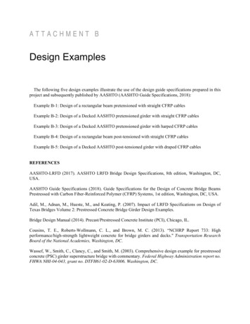
Example B-2: Design of a Decked AASHTO girder pretensioned with straight CFRP cablesThe bridge considered for this design example has a span length of 90 ft. (center-to-center (c/c) pierdistance), a total width of 36 ft., and total roadway width of 34 ft. The bridge superstructure consists ofsix AASHTO Type IV girders spaced 6 ft. center-to-center, designed to act compositely with an 8 in.thick cast-in-place (CIP) concrete deck. The wearing surface thickness is 2.0 in., which includes thethickness of any future wearing surface. T501 type rails are considered in the design. HL-93 is thedesign live load. A relative humidity (RH) of 60 percent is considered in the design. The design isperformed for an interior girder based on service and strength limit states according to AASHTO-LRFD(2017) and AASHTO Guide Specifications (2018). They are referred in the following example asAASHTO and AASHTO-CFRP respectively.8"-DeckAASHTO Type-IVOverall beam LengthLspan 91 ftDesign SpanLdesign 90 ftGirder spacinggspacing 6 ftNumber of beamsNbeams 6Total roadway widthwroadway 36 ftCast in Place Deck:Structural thickness, (effective)hd 7.5 inB 2-1
Actual thickness, (for dead load calculation)ts 8 inConcrete strength at 28 days,f'cDeck 6.0 ksiThickness of asphalt-wearing surface (including anyfuture wearing surface)hws 2 inUnit weight of concreteγc 150 pcfHaunch thicknesshh 0.5 inPrecast Girders: AASHTO Type IVConcrete strength at release,f'ci 6.0 ksiConcrete strength at 28 days,f'c 9.0 ksiUnit weight of concreteγc 150 pcfPrestressing CFRPDiameter of one prestressing CFRP cabledb 0.6 inArea of one prestressing CFRP cableApf 0.18 in 2Design tensile stress64.14 kipfpu ――― 356.33 ksiApfModulus of elasticity (AASHTO-CFRPArt. 1.4.1.3)Ef 22500 ksiDesign tensile strainfpuεpu ― 0.016EfStress limitation for prestressing CFRP(AASHTO-CFRP Art. 1.9.1)Before transferfpi 0.70 fpu 249.43 ksiAt service, after all lossesfpe 0.65 fpu 231.62 ksiNonprestressed Reinforcement:Yield strengthfy 60 ksiB 2-2
Modulus of elasticity (AASHTO Art. 5.4.4.2)Es 29000 ksiUnit weight of concreteγaws 150 pcfT501 type barrier weight/sideγbw 326 plfSection Properties of AASHTO Type IV Girder:Cross-section area of girderAg 789 in 2Moment of inertia of about the centroid of the noncompositeprecast girderIg 260730 in 4Weight of the girderkipwg 0.822 ――ftHeight of girderhg 54 inWidth of bottom rectangular flangebbrf 26 inHeight of bottom rectangular flangehbrf 8 inWidth of bottom tapered flangebbtf 9 inHeight of bottom tapered flangehbtf 9 inWidth of webbw 8 inHeight of webhw 23 inWidth of top rectangular flangebtrf 20 inB 2-3
Height of top rectangular flangehtrf 8 inWidth of top tapered flangebttf 6 inHeight of top tapered flangehttf 6 inDistance from centroid to the extreme bottom fiber ofthe non-composite precast girderygbot 24.73 inDistance from centroid to the extreme top fiber of thenon-composite precast girderygtop hg - ygbot 29.27 inSection modulus referenced to the extreme bottom fiber ofthe non-composite precast girderIg 1.05 10 4 in 3Sgbot ――ygbotSection modulus referenced to the extreme top fiber of thenon-composite precast girderIg 8.91 10 3 in 3Sgtop ――ygtopEffective flange width (AASHTO Art. 4.6.2.6.1)Average spacing of adjacent girdersbe gspacing 72 inMaterial Properties for Girder and Deck Concrete:At release γc 2.0 f'c 0.33E f'c 12 ―― ― psi pcf psi Eci E f'ci 4.77 10 3 ksiAt 28 days (Girder)Ec E f'c 5.45 10 3 ksiAt 28 days (Deck)EcDeck E f'cDeck 4.77 10 3 ksiModulus of elasticity of concrete [AASHTO Art. 5.4.2.4]‾‾‾f'c― ksiksiModulus of rupture of concrete [AASHTO Art 5.4.2.6]fmr f'c 0.24 At releasefri fmr f'ci 0.59 ksiAt 28 days (Girder)fr fmr f'c 0.72 ksiAt 28 days (Deck)frDeck fmr f'cDeck 0.59 ksiEcDeckn1 ―― 0.87Ec[Modular ratio for transformed section]B 2-4
Section Properties of Composite Deck:Height of deckhd 7.5 inTransformed width of deckbd n1 be 62.98 inCross-section area of deckAd hd bd 472.37 in 2Moment of inertia of deck about it centriodWeight of the deckbd hd 3 2.21 10 3 in 4Id ―――12kipwd be ts γc 0.6 ――ftDue to camber of the precast, prestressed beam, a minimum haunch thickness of 1/2 in. at midspan isconsidered in the structural properties of the composite section. Also, the width of haunch must betransformed.Height of haunchhh 0.5 inWidth of haunchbh btrf 20 inTransformed width of haunchbth n1 bh 17.5 inArea of haunchAh hh bth 8.75 in 2Moment of inertia of haunch about it centriodbth hh 3 0.18 in 4Ih ―――12kipwh bh hh γc 0.0104 ――ftWeight of the haunchTotal height of composite beamhc hd hg hh 62 inTotal area of composite beamAc Ad Ag Ah 1.27 10 3 in 2Total weight of the compositebeamkipwc wg wd wh 1.43 ――ftNeutral axis location from bottomfor composite beam hd hh Ag ygbot Ad hc - ― Ah hg ― 2 2 ycbot ――――――――――― 37.4 inAg A d A hNeutral axis location from top forcomposite beamMoment of inertia of composite beamyctop hc - ycbot 24.6 inB 2-5
22 hd hh 54Icomp Ig Id Ih Ag ycbot - ygbot Ad yctop - ― Ah yctop - hd - ― 5.97 10 in2 2 2Shear Force and Bending Moment Due to Dead LoadsDead loads:Dead loads acting on the non-composite structure:kipwg 0.822 ――ftSelf-weight of the girderWeight of cast-in-place deck on each interior girderkipwd 0.6 ――ftWeight of haunch on each interior girderkipwh 0.01 ――ftkipwT wg wd wh 1.43 ――ftTotal dead load on non-composite sectionSuperimposed dead loads:Dead and live load on the deck must be distributed to the precast, prestressed beams. AASHTOprovides factors for the distribution of live load into the beams. The same factors can be used fordead loads if the following criteria is met [AASHTO Art. 4.6.2.2.1]: Width of deck is constant [OK] Number of beams is not less than four,‖ if Nbeams 4‖‖‖ ‖ “NOT OK”‖ else‖“OK”‖ ‖‖ ‖ “OK” Beams are parallel and have approximately the same stiffness The overhang minus the barrier width does not exceed 3.0 feetDe Overhang - 17 inB 2-6
Overhang 3 ftDe Overhang - 17 in 19 in‖ if D 3 fte‖‖ ‖“NOTOK”‖‖ else‖“OK”‖ ‖‖ ‖ “OK”Curvature in plan is less than the limit specified in Article 4.6.1.2.4 [OK]Cross section of the bridge is consistent with one of the cross sections given inAASHTO Table 4.6.2.2.1-1 Precast concrete I sections are specified as Type k [OK]Because all of the above criteria are satisfied, the barrier and wearing surface loads are equallydistributed among the six girders. Weight of T501 rails or barriers on each girder γbw kipwb 2 ―― 0.11 ――ft 6 Weight of 2.0 in. wearing surfacekipwws1 γaws hws 0.03 ――ft 2This load is applied over the entire clear roadway width.Weight of wearing surface on each girderwws1 wroadwaykip 0.15 ――wws ――――6ftTotal superimposed dead loadkipwSD wb wws 0.26 ――ftCalculate modular ratio between girder and deck [AASHTO Eq. 4.6.2.2.1-2]Ecn ―― 1.14EcDeckB 2-7
Calculate eg , the distance between the center of gravity of the non-composite beam and the deck.Ignore the thickness of the haunch in determining eg . It is also possible to ignore the integral wearingsurface, i.e, use hd 7.5 in . However, the difference in the distribution factor will be minimal.hd 33.02 ineg ygtop ―2Calculate Kg , the longitudinal stiffness parameter. [AASHTO Eq. 4.6.2.2.1-1]Kg n Ig Ag eg 2 1.28 10 6 in 4Moment Distribution FactorsInterior girder type k [AASHTO Art. 4.6.2.2.2 b]Distribution factor for moment when one design lane is loaded 0.1Kg S 0.4 S 0.3 DM.Interior 0.06 ― ― ――― 14 L 12 L ts 3 Using variables defined in this example gspacing 0.4 ――― 0.71 14 ft gspacing 0.3 ――― 0.44 Ldesign 0.1Kg ―――― 1.113 Ldesign hd gspacing 0.4 gspacing 0.3 0.1KgDM.Interior1 0.06 ――― ――― ―――― 0.41 14 ft Ldesign Ldesign hd 3 Distribution factor for moment when two design lanes are loaded 0.1Kg S 0.6 S 0.2 DM.Interior 0.075 ―― ―――― 9.5 L 12 L ts 3 Using variables defined in this example gspacing 0.6 gspacing 0.2 0.1KgDM.Interior2 0.075 ――― ――― ―――― 0.56 9.5 ft Ldesign Ldesign hd 3 The greater distribution factor is selected for moment design of the beams.DM.Interior max DM.Interior1 , DM.Interior2 0.56B 2-8hd 7.5 in
Check for range of applicabilityDM.Interior ‖ S gspacing 3.5 ft gspacing 16 ft 0.56‖ ‖ ts hd 4.5 in hd 12 in ‖ L Ldesign 20 ft Ldesign 240 ft ‖ ‖ Nb Nbeams 4 ‖ Kg Kg 10000 in 4 Kg 7000000 in 4 ‖ ‖ if S ts L Nb Kg ‖‖ DM.Interior‖ ‖‖ else‖ ‖“Does not satisfy range of applicability”‖ ‖Exterior girder [AASHTO Art. 4.6.2.2.2 d]De S - 2 ftP1 ――――SDe S - 8 ftP2 ――――SDe Overhang - 17 inOverhang 3 ftDe Overhang - 17 in 19 inS gspacing 6 ftThe distribution factor for one design lanes loaded is based on the lever rule, which includes a 0.5factor for converting the truck load to wheel loads and a 1.2 factor for multiple truck presence. 2 S 2 De - 8 ftS De - 2 ft 0.5 , ―――― 0.5 1.2 0.56DM.Exterior1 if (2 ft 6 ft) De S , ―――――SS The distribution factor for two design lane loaded De DM.Exterior DM.Interior 0.77 ―― 9.1 Using variables defined in this example, De DM.Exterior2 DM.Interior2 0.77 ―― 0.539.1 ft B 2-9
DM.Exterior max DM.Exterior1 , DM.Exterior2 0.56Range of applicabilityDM.Exterior ‖ de De -1 ft De 5.5 ft ‖‖ if de ‖ ‖D‖ ‖ M.Exterior‖ else‖ ‖“Does not satisfy range of applicability”‖ ‖ 0.56For fatigue limit stateThe commentary of article 3.4.1 in the AASHTO LRFD specification states that for fatigue limitstate a single design truck should be used. However, live load distribution factors given inAASHTO Art 4.6.2.2 take into consideration the multiple presence factor, m. AASHTO Art3.6.1.1.2 states that the multiple presence factor, m, for one design lane loaded is 1.2. Therefore, thedistribution factor for one design lane loaded with the multiple presence factor removed should beused.DM.Interior1Distribution factor for fatigue limit state 0.34DMF.Interior ―――1.2Shear Distribution FactorsInterior girder [AASHTO Art. 4.6.2.2.3 a]Distribution factor for shear when one design lane is loaded S DS.Interior 0.36 ― 25 Using variables defined in this example gspacing ――― 0.24 25 ft gspacing DS.Interior1 0.36 ―― 0.6 25 ft Distribution factor for shear when two design lanes are loaded S S 2.0DS.Interior 0.2 ― - ― 12 35 B 2-10
Using variables defined in this example gspacing gspacing 2DS.Interior2 0.075 ――― - ――― 0.55 12 ft 35 ft The greater distribution factor is selected for moment design of the beams.DS.Interior max DS.Interior1 , DS.Interior2 0.6Check for range of applicability 0.6DS.Interior ‖ S gspacing 3.5 ft gspacing 16 ft ‖‖ ts hd 4.5 in hd 12 in ‖ L Ldesign 20 ft Ldesign 240 ft ‖ ‖ Nb Nbeams 4 ‖ Kg Kg 10000 in 4 Kg 7000000 in 4 ‖ ‖ if S ts L Nb Kg ‖ ‖ DS.Interior‖ ‖‖ else‖ ‖“Does not satisfy range of applicability”‖ ‖The AASHTO Specifications specify the dynamic load effects as a percentage of the static live loadeffects. AASHTO Table 3.6.2.1-1 specifies the dynamic allowance to be taken as 33 percent of thestatic load effects for all limit states, except the fatigue limit state, and 15 percent for the fatiguelimit state. The factor to be applied to the static load shall be taken as:(1 IM/100)where:IM Dynamic load allowance, applied to truck load or tandem load only 33 for all limit states except the fatigue limit state 15 for fatigue limit stateB 2-11
The maximum shear forces and bending moments due to HS 20-44 truck loading for all limit statesis calculated using the influence line approach. The live load moments and shear forces for thesimple span is computed by positioning the axle load of HS-20 truck in following locationsCase I: HS-20 truck moment and shearP2 32 kipP1 32 kipP3 8 kipx 5 ft[Initialize value] Ldesign - x Ldesign - x - 14 ft Ldesign - x - 28 ft Mtruck1 (x) P1 ―――― x P2 ―――――― x P3 ―――――― xLdesignLdesignLdesign Ldesign - x Ldesign - x - 14 ft Ldesign - x - 28 ft P2 ―――――― P3 ――――――Vtruck1 (x) P1 ――――LdesignLdesignLdesignCase II: HS-20 truck moment and shear Ldesign - x Ldesign - x Ldesign - x - 14 ft Mtruck2 (x) P1 ―――― (x - 14 ft) P2 ―――― x P3 ―――――― xLdesignLdesignLdesign Ldesign - x Ldesign - x - 14 ft -(x - 14 ft)Vtruck2 (x) P1 ―――― P2 ―――― P3 ――――――LdesignLdesignLdesignB 2-12
Mtruck1 maximize Mtruck1 , x 1.3 10 3 ft·kipMtruck2 maximize Mtruck2 , x 1.34 10 3 ft·kipMaximum bending moment due to HS 20-44 truck loadM 1.344 10 3 ft·kipThe calculation of shear force is carried out later for the critical shear section.Distributed bending moment due to truck load including dynamic load allowance ( MLT ) is calculatedas follows:MLT (Moment per lane due to truck load)(DFM)(1 IM/100)IM 33DM.Interior 0.56 IM 3 MLT M DM.Interior 1 ―― 1.01 10 ft kip100 The maximum bending moments ( ML ) due to a uniformly distributed lane
Guide Specifications for the Design of Concrete Bridge Beams Prestressed with Carbon Fiber-Reinforced Polymer (CFRP) Systems, 1st edition, Washington, DC, USA. Adil, M., Adnan, M., Hueste, M., and Keating, P. (2007). Impact of LRFD Specifications on Design of Texas Bridges Volume 2: Prestressed Concrete Bridge Girder Design Examples.