Transcription
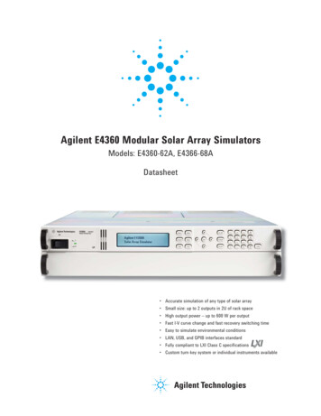
Agilent E4360 Modular Solar Array SimulatorsModels: E4360-62A, E4366-68ADatasheet Accurate simulation of any type of solar array Small size: up to 2 outputs in 2U of rack space High output power – up to 600 W per output Fast I-V curve change and fast recovery switching time Easy to simulate environmental conditions LAN, USB, and GPIB interfaces standard Fully compliant to LXI Class C specifications Custom turn-key system or individual instruments available
Solar Array SimulationSatellite Test ApplicationsSolar panels consisting ofmultiple solar cells providepower to satellites. They haveunique I-V characteristics.Since the output power varieswith environmental conditions(temperature, irradiation)and operational conditions(eclipse, spin), a specializedpower supply such as the solararray simulator (SAS) must beused for making accurate testsand veryifying the satellitepower system.Residential Photovoltaic(PV) Test applicationsSolar panels are also used inresidential power systems toprovide power to homes. Eachsolar panel output can be connected to a microinverter thatconverts the DC solar paneloutput into AC for use in thehome. To test microinverters,a solar array simulator is usedto verify that the microinverterwill track the maximum powerpoint under various environmental conditions (such as sunnyconditions, cloudy conditions,shadowing, and different temperatures) and to ensure thatthe microinverter is reliableand efficient.As the trend moves towardhigher power solar panels andmore efficient inverters, thereis a need for a specialized DCpower source that is reliable, repeatable, scalable, cost effective,and available off the shelf.Satellite manufacturers need toverify the design of the powerbus regulator on the ground.Microinverter and DC poweroptimizer designers need toverify accuracy and efficiencyof the device to gain competitiveadvantage in the marketplace.Agilent Solar Array SimulatorThe Agilent E4360 ModularSolar Array Simulator (SAS)is a dual output programmabledc power source that simulatesthe output characteristics of asolar array. The E4360 SAS isprimarily a current source withvery low output capacitance andis capable of quickly simulatingthe I-V curve of different arraysunder different conditions (ex.temperature, age etc.). It provides up to 2 outputs and upto 1200 W in a small 2U-highmainframe.Whether you build your own testsystem requiring instrument onlyor if you want a full turn-keysystem with all the instrumentsand software integrated andinstalled – Agilent gives you theflexibility you need. The E4360SAS is readily available as anoff-the-shelf instrument andalso is available from Agilentintegrated into a full turn-keysolar array simulator systemconfigured to your exactspecification.Multiple Simulation ModesThe E4360 SAS provides threeoperating modes, Simulator(SAS), Table and Fixed modes.To accurately simulate the I-Vcure of a solar array, use SASor table modes. When a standardpower supply is needed, usefixed mode.1. SAS Mode:The E4360 SAS internallygenerates a 4,096 I-V pointtable. An internal algorithmis used to approximate anI-V curve. This can be donevia the I/O interfaces or fromthe front panel where a PCis not needed. These fourinput parameters are neededto establish a curve in thismode: Voc - open circuit voltage Isc - short circuit current Imp - current at the peakpower point on the curve Vmp - voltage at the peakpower point on the curveIscFigure 1: Power supply outputcharacteristic in SAS mode2
2. Table Mode:The I-V curve is determinedby a user-defined table ofpoints. A table can have aminimum of 3 points, up toa maximum of 4000 points.A point corresponds to aspecific value of I and V.As many as 30 tables maybe stored in each of theE4360 SAS built-in volatileand non-volatile memory.The tables (I-V curve) storedin this non-volatile memorywill be retained when thepower is turned off, whilethose stored in volatile memorywill be erased after power isremoved.Additionally, current andvoltage offsets can be appliedto the selected table to simulate a change in the operatingconditions of the solar array.Fast I-V Curve ChangesThe E4360 offers fast curvechanges to enable better simulation of solar arrays undervarious environmental conditions, like eclipse and spin. Theresolution of the I-V curve canbe set to optimize the I-V curvefor resolution or fast curvechange. In simulation (SAS)mode and table mode, you canselect high resolution whichuses a 4,096 point table togenerate a smoother I-V curvewithin 350 msec. For fast I-Vcurve generation, you can selectthe 256 point table that quicklygenerates an I-V curve within30 msec. All the E4360 SAS inthe system can be synchronizedto change their I-V curves at thesame time using the hardwaretrigger, such that I-V curves canbe changed on up to 100 outputswithin 30 msec or 350 msecbased on resolution setting.I-V Curve ListThe E4360 offers a LIST modethat lets you pre-program a LISTof up to 512 I-V curves. Programup to 512 sets of points, whereeach set of points include curveparameters: Voc, Vmp, Isc, andImp. A dwell time of 30 ms to33,554 seconds with 1 ms resolution can be specified and theE4360 SAS will stay (i.e. dwell) atthe set point for the programmeddwell time value. Alternately,the LIST can be paced (advancedto the next set point) by a bustrigger or it can be paced by atrigger signal which enablessynchronization of the LISTwith an external event. Utilizing I-V curve lists speed uptest execution by removing thecomputer I/O from the processand simplifies I-V curve changemore easily simulating the solararray under various conditions.Small SizeThe Agilent E4360 provides upto 1200 W in a small 2U high,19 inch wide package. It hasside air vents, however 1Uspace is required between theinstruments to retain propercooling.3. Fixed Mode:This is the default modewhen the unit is powered on.The unit has the rectangularI-V characteristics of astandard power supply.Figure 2: Power supply output characteristicin Fixed mode3
Built-in Measurementof Voltage and CurrentThe E4360 modules comestandard with built-in measurement of voltage and current.Measurements can be quicklymade on up to 100 outputs inless than 500 msec using thehardware trigger. Additionally,the E4360 can simultaneouslydata log both voltage and current at 10 readings/s.Protection FeaturesTo safeguard your device fromdamage, the E4360 module hasover-voltage, over-current, andover-temperature protection.The E4360 can be configuredsuch that a fault condition inone module can be detectedwithin 10 microseconds byother modules so that theycan be quickly shut down toavoid hazardous conditionson your DUT.SecurityWhen used in systems runningGPIB, the LAN and/or USBinterfaces can be passwordprotected and disabled forextra security.Control from any BrowserThe built-in web server providesremote access and control ofthe E4360 via a standard webbrowser. From the web browser,you can setup, monitor andoperate the E4360 remotely.Easy Parallel OperationShould you need greater outputpower and current, the E4360gives you the flexibility to connect similarly rated outputs inparallel. To simplify paralleloperation, the E4360 offers afirmware based feature thatallows it to treat 2 channels asa single, synchronized channel.Once configured, all functions(sourcing, programming, measurements, triggering, protection, and status monitoring)behave as if there is a singlechannel with twice the outputcurrent and power capability.Plug High Power Mainframesinto Standard AC Sockets forQuick Bench CheckoutWhen you first turn on theE4360A Modular SAS mainframe,the mainframe automaticallysenses the voltage availablefrom the AC line. If the AC linevoltage is 180 Vac, the mainframe automatically scales backthe available output power toprevent overloading the AC linecord. The E4360A will limit themainframe output power to600 W allowing the high powerConnectivityThe E4360 Modular Solar ArraySimulator comes standard withGPIB, 10/100 Base-T EthernetLAN interfaces, and USB 2.0interfaces, giving you the flexibility to use your interface ofchoice today and in the future.The E4360 is fully compliantwith the LXI Class C specification.Figure 3: Built-in ethernet, USB 2.0, and GPIB interfaces enables easy system connections4
mainframe to be plugged intoany standard outlet. If there isonly one module installed thenfull power will be available fromthat module. When two modulesare installed, the output powerof each module would be cut inhalf (300 W per module). Thisis very convenient for initialbench checkout of the SAS. Itis also very convenient for testdevelopment, which is typicallydone on the bench when DUTis not yet driven to full power.Agilent 14360A System Control ToolsThe 14360A System Control Toolsis a powerful software driver thatgreatly simplifies the programming and control of a systemwith multiple E4360A SAS powersupplies. It is shipped standardwith every E4360 Modular Mainframe – free of cost. There arethree components of the 14360ASystem Control Tools: the systemdriver, the configuration wizard,and the server control.The System DriverTriggeringThe E4360 Modular Solar ArraySimulator mainframe has hardware trigger in/trigger out signalswhich permit the E4360 to besynchronized with externalevents. For example, all SAS ina system can be synchronized tochange their I-V curve, to takea voltage and current measurement, or to start a data logging.The 14360 system driverinterfaces with the user’s testapplication and provides thecapability for a single functioncall to control up to 100 E4360SAS outputs (50 mainframes).The driver functions providesupport for many tasks likeconfiguration measurement,DriversThe E4360 comes with both theIVI-COM driver and the SystemControl Tools.Figure 4: Agilent E4360A built-in web server5and status readback of a system. It enables you to set andmeasure voltage and currentlevels, operating modes (Fixed,SAS, Table), protection levels,SAS mode settings (Isc, Voc,Imp, Vmp) and much more.The driver supports VISA andTCP/IP sockets connection.The Configuration WizardThe configuration wizard is agraphical user interface (GUI)that lets you easily search forand configure the layout of theE4360 SAS system withoutwriting a single line of code.Simply specify the instrumentsearch parameters, createmodule groups and segments,and drag and drop modules todesired segments. This wizardgenerates a configuration fileused to initialize the systemdriver.
Server ControlThe server control allows accessto the system by multiple applications and an internet browserweb monitor for viewing thestatus of the system.The server control utilizes aclient-server model, enablinga remote PC to communicatewith the SAS system PC. Throughthe use of dual Ethernet cardsin the PC running the servercontrol, clients can access theSAS system remotely. Placingthe SAS system on its own private network simplifies systemmaintenance and new systemdevelopment allowing systemconfigurations to be duplicated.The web monitor allows youto remotely monitor yoursystem of E4360s. From anyweb browser, you can view theoverall system driver status,the system layout along withmodule measurement and status, and more. It also providesa linkage to the webGUI thatis available for an individualE4360 instrument allowing youto configure and control thatinstrument. The webGUI canbe password protected. This isa great tool for monitoring andtroubleshooting a system ofE4360s.Figure 5: Agilent 14360A system control tools: configuration wizardProgramming LanguageThe E4360 supports easy-to-useSCPI (Standard Commands forProgrammable Instruments).Firmware UpdatesThe E4360 firmware is stored inFLASH ROM and can be easilyupdated when new features become available. Firmware canbe downloaded into the E4360over GPIB, LAN, or USB usingthe supplied firmware updateutility program. Firmwareupdates can be found atwww.agilent.com/find/E4360firmware.Front PanelIn addition to full control overits three standard interfaces,the E4360 has a full featuredfront panel to permit easy manualoperation for test prototyping,debugging, and troubleshootingwhen used in an ATE system.You can have confidence thatthe E4360 is working properlybecause you can view the settings and actual output valueson both outputs at the sametime. Further, all SAS modescan be programmed and controlled from the front panel.Analog Programming and MonitoringIn fixed mode, the output currentcan be programmed from zeroto full scale by an analog voltageof 0 to - 4 V.6
Universal AC InputThe E4360 has a universal inputthat operates from 100-240Vac, 50/60/400 Hz. There areno switches to set or fuses tochange when switching fromone voltage standard to another.The ac input employs powerfactor correction. In order toget full output power when amainframe is configured with twomodules, it must be connectedto an ac input of 180 Vac; elseoutput power will be limited to600 W.Quick DisconnectsEach power module has quickdisconnects for easy systemsetup and maintenance.Rack Mount KitThe E3460 is easily rack-mountedusing available option 908. Thiskit provides all the necessaryhardware to rack mount oneE4360A mainframe in 2U ofrack space. This rack mount kitincludes front rack ears andrear supports which take theplace of standard rack railsand/or slides.Custom Turn-Key SystemAgilent offers an affordable fullturn-key solar array simulatorsystem with all the instruments,and software integrated andinstalled. Save valuable systemdevelopment time by lettingAgilent handle all the systemdesign elements. This SASsystem is built on the E4360Modular Solar Array Simulatorplatform making this systemthe smallest available on themarket. The E4360 modulararchitecture makes it easy toconfigure, re-configure, andsupport this system since modules can be easily moved andreplaced. Further the system’scomponents are made up ofcommercial-off-the-shelf instruments, a standard PC andstandard interconnectivity (LAN,USB) for lower cost, easier support, and reduced down time.Agilent will tailor the systemto your exact specification.Contact your local Agilentsales office to learn moreabout our custom systems.While the scope of this serviceis usually limited to the modification of a standard SAS, ourengineers welcome a discussionto determine the feasibility ofmeeting your specific requirements. Contact your localAgilent sales office with yourmodification request.Whether you need spares, wantto configure the system yourselfor want Agilent to build yoursystem – the E4360 gives youthe flexibility to choose theconfiguration that best meetsyour test strategy.Modification ServiceWhile the E4360 Modular SolarArray Simulator will meet mostof your needs, Agilent recognizesthat these SAS may not matchall needs. To better solve yourspecific problem, Agilent offersa special modification service.This service entails the designand manufacture of a modifiedversion of standard E4360 SASmodels. Typical modificationsinclude changes to the maximumoutput voltage or current withinthe power ratings. The modifiedSAS are designed, manufactured,tested, to Agilent’s high qualityand reliability standards.7Figure 6: Custom turnkey system
Performance Specifications for Agilent E4361A and E4362A SAS ModulesUnless otherwise noted, specifications are warranted over the ambient temperature range of 0 C to 40 Cand are applicable for Fixed, Simulator, and Table modesE4361AOutput Ratings(Simulator andTable mode)Output Ratings(Fixed Mode)E4362AE4362A-J01E4362A-J02Maximum Power510 W600 W594 W594 WMaximum Open Circuit Voltage (Voc)65 V130 V117 V120 VMaximum Voltage Point (Vmp)60 V120 V108 V110 VLine Voltage:200 V/230 V/240 VMaximum Short Circuit Current (Isc)8.5 A5.0 A5.5 A5.4 AMaximum Circuit Point (Imp)18.5 A5.0 A5.5 A5.4 ALine Voltage:4100 V/120 VMaximum Short Circuit Current (Isc)4.25 A2.5 A2.75 A2.7 AMaximum Current Point (Imp)14.25 A2.5 A2.75 A2.7 A0.25 Ω1Ω1Ω1ΩMinimum Impedance( V/ Vl)1VoltageLine Voltage:200 V/230 V/240 VLine Voltage:4100 V/120 V0 - 60 V0 - 120 V0 - 108 V0 - 110 VCurrent0 - 8.5 A0 - 5.0 A0 - 5.5 A0 - 5.4 ACurrent0 - 4.25 A0 - 2.5 A0 - 2.75 A0 - 2.7 A0.11 A/ C0.069 A/ C0.069 A/ C0.068 A/ C20 mVrms125 mVp-p24 mVrms195 mVp-p24 mVrms195 mVp-p24 mVrms195 mVp-pCurrent Derating Factor(from 40 C to 55 C)Output Voltage Ripple & Noise(from 20 Hz to 20 MHz with aresistive load, outputs ungrounded,or either output grounded)Simulator/Table modeFixed mode (constant voltage)24 mVrms30 mVrms30 mVrms30 mVrms150 mVp-p150 mVp-p150 mVp-p150 mVp-pProgramming Accuracy2,3Fixed Mode Voltage0.075% 25 mV0.075% 50 mV 0.075% 50 mV0.075% 50 mV(@ 23 C 5 C)Fixed Mode Current0.2% 20 mA0.2% 10 mA0.2% 11 mA0.2% 11 mAReadback Accuracy3(from front panel or over GPIB withrespect to actual output @ 23 5 C)Voltage0.08% 25 mV0.08% 50 mV0.08% 50 mV0.08% 50 mV Current0.20% 20 mA0.20% 10 mA0.20% 11 mA0.20% 11 mA Current0.35% 48 mA0.35% 24 mA0.35% 26 mA0.35% 26 mALoad Regulation – Fixed Mode(change in output voltage or current forany load change within ratings)Constant voltage2 mV2 mV2 mV2 mVConstant current1 mA1 mA1 mA1 mALine Regulation – Fixed Mode(change in output voltage or current forany line voltage change within ratings)Constant voltage2 mV2 mV2 mV2 mVConstant current1 mA1 mA1 mA1 mA1 There is no maximum impedance restriction. The programmed value for Imp can be less than or equal to Isc.2 In Simulator mode, the output current is related to the readback output voltage by an internal algorithm. In Table mode, the output current is relatedto the readback output voltage by interpolation between points that are entered by the user.3 The unit may go out of specification when subjected to RF fields of 3 volts/meter in the frequency range of 26 MHz to 1 GHz.4 There is no current derating when only one output module is installed in the mainframe.8
Performance Specifications for Agilent E4361A and E4362A SAS Modules (Continued)Unless otherwise noted, specifications are warranted over the ambient temperature range of 0 C to 40 Cand are applicable for Fixed, Simulator, and Table modesE4361A-J01Output Ratings(Simulator andTable mode)E4362A-J03E4362A-J04E4362A-J05Maximum Power498 W598 W596 W552.5 WMaximum Open Circuit Voltage (Voc)58 V108 V170 V95 VMaximum Voltage Point (Vmp)53.5 V99.7 V157 V87.7 VLine Voltage:200 V/230 V/240 VMaximum Short Circuit Current (Isc)9.3 A6A3.8 A6.3 AMaximum Current Point (Imp)19.3 A6A3.8 A6.3 ALine Voltage:4100 V/120 VMaximum Short Circuit Current (Isc)4.65 A3A1.9 A3.15 AMaximum Current Point (Imp)4.65 A3A1.9 A3.15 A1Ω1Ω1.72 Ω1ΩMinimum Impedance( V/ Vl)1Output RatingsVoltage(Fixed Mode)Line Voltage:200 V/230 V/240 VLine Voltage:4100 V/120 V0 - 53.5 V0 - 99.7 V0 - 157 V0 - 87.7 VCurrent0 - 9.3 A0-6A0 - 3.8 A0 - 6.3 ACurrent0 - 4.65 A0-3A0 - 1.9 A0 - 3.15 A0.12 A/ C0.075 A/ C0.048 A/ C0.079 A/ C20 mVrms125 mVp-p23 mVrms175 mVp-p32 mVrms250 mVp-p22 mVrms158 mVp-pCurrent Derating Factor(from 40 C to 55 C)Output Voltage Ripple & Noise(from 20 Hz to 20 MHz with aresistive load, outputs ungrounded,or either output grounded)Simulator/Table modeFixed mode (constant voltage)24 mVrms28 mVrms40 mVrms27 mVrms150 mVp-p150 mVp-p195 mVp-p150 mVp-pProgramming Accuracy2,3(@ 23 C 5 C)Fixed Mode Voltage0.075% 22 mV0.075% 42 mV 0.075% 65 mV0.075% 37 mVFixed Mode Current0.2% 22 mA0.2% 12 mA0.2% 8 mA0.2% 15 mAReadback Accuracy3(from front panel or over GPIB withrespect to actual output @ 23 5 C)Voltage0.08% 22 mV0.08% 42 mV0.08% 65 mV0.08% 37 mV Current0.20% 23 mA0.20% 12 mA0.20% 8 mA0.20% 15 mA Current0.35% 53 mA0.35% 29 mA0.35% 19 mA0.35% 36 mALoad Regulation – Fixed Mode(change in output voltage or current forany load change within ratings)Constant voltage2 mV3 mV3 mV2 mVConstant current1 mA1 mA1 mA1 mALine Regulation – Fixed Mode(change in output voltage or current forany line voltage change within ratings)Constant voltage2 mV2 mV2 mV2 mVConstant current1 mA1 mA1 mA1 mV1 There is no maximum impedance restriction. The programmed value for Imp can be less than or equal to Isc.2 In Simulator mode, the output current is related to the readback output voltage by an internal algorithm. In Table mode, the output current is relatedto the readback output voltage by interpolation between points that are entered by the user.3 The unit may go out of specification when subjected to RF fields of 3 volts/meter in the frequency range of 26 MHz to 1 GHz.4 There is no current derating when only one output module is installed in the mainframe.9
Supplemental Characteristics for Agilent E4361A and E4362A SAS ModulesSupplemental characteristics are not warranted but are descriptions of typical performance determined eitherby design or type testing.Output Current Ripple & Noise(from 20 Hz to 20 MHz with aresistive load, outputs ungrounded,or either output grounded)Output ProgrammingRange(maximumLine Voltage:programmable200 V/230 V/240 Vvalues)Line Voltage:100 V/120 V 1Programming Resolution(average values)Programming AccuracySimulator/Table modeFixed mode (constant current)E4361AE4362AE4362A-J01E4362A-J024 mArms32 mAp-p4 mArms32 mAp-p4 mArms32 mAp-p4 mArms32 mAp-p2.5 mArms2.5 mArms3 mArms3 mArms19 mAp-p19 mAp-p20 mAp-p20 mAp-pSimulator/Table mode VoltageFixed mode Voltage0 - 65 V0 - 61.5 V0 - 130 V0 - 123 V0 - 117 V0 - 110.7 V0 - 120 V0 - 112.8 VCurrent0 - 8.66 A0 - 5.1 A0 - 5.61 A0 - 5.51 ACurrent0 - 4.33 A0 - 2.55 A0 - 2.81 A0 - 2.75 AOvervoltage Protection0 - 74 V0 -140 V0 -127 V0 -129 VOvercurrent Limit0 - 10.6 A0 - 6.25 A0 - 6.88 A0 - 6.75 AVoltage19 mV37 mV35 mV35 mVCurrent2.7 mA1.6 mA1.8 mA1.7 mAOvervoltage Protection325 mV600 mV575 mV575 mVOvercurrent Limit46 mA27 mA31 mA30 mA1.1 VOvervoltage Protection0.65 V1.2 V1.1 VOvercurrent Limit0.5% 215 mA0.5% 125 mA0.5% 140 mA0.5% 135 mACurrent Monitor (referenced to P common)1.0% 130 mA1.0% 75 mA1.0% 85 mA1.0% 81 mAFixed Mode AnalogAnalog Programming1.0% 5.5 mA1.0% 3.2 mA1.0% 3.5 mA1.0% 3.4 mACurrent Programming Ip to Ip Differential Input(0 to full scale)0 to -4 V0 to -4 V0 to -4 V0 to -4 VMax. common mode voltage(referenced to OUT) 18 V 18 V 18 V 18 VNominal Input Impedance20 kΩ20 kΩ20 kΩ20 kΩDrift/Temperature Stability(change in output over 8 hours underconstant load, line, and ambient,following a 30 minute warmup)Voltage0.04% 1 mV0.04% 2 mV0.04% 2 mV0.04% 2 mVCurrent0.1% 0.85 mA0.1% 0.5 mA0.1% 0.55 mA0.1% 0.54 mATemperature Coefficients(output change per C)Voltage0.01% 325 μV0.01% 650 μV0.01% 650 μV0.01% 650 μVCurrent0.025% 215 μA0.025% 125 μA 0.025% 140 μA0.025% 135 μAOutput Capacitance 100 nF 50 nF 50 nF 50 nFMaximum Reverse Diode Current(with fans running)8.5 A5.0 A5.5 A5.4 A1 There is no current derating when only one output module is installed in the mainframe.10
Supplemental Characteristics for Agilent E4361A and E4362A SAS Modules (Continued)Supplemental characteristics are not warranted but are descriptions of typical performance determined eitherby design or type testing.Output Current Ripple & Noise(from 20 Hz to 20 MHz with aresistive load, outputs ungrounded,or either output grounded)Simulator/Table modeOutput ProgrammingRange(maximumLine Voltage:programmable200 V/230 V/240 Vvalues)Line Voltage:100 V/120 V 1Programming Resolution(average values)Fixed mode (constant current)E4361A-J01E4362A-J03E4362A-J04E4362A-J054 mArms32 mAp-p4 mArms32 mAp-p4 mArms32 mAp-p4 mArms32 mAp-p2.5 mArms2.5 mArms2.5 mArms2.5 mArms19 mAp-p19 mAp-p19 mAp-p19 mAp-pSimulator/Table mode VoltageFixed mode Voltage0 - 58 V0 - 54.8 V0 - 108 V0 - 102.2 V0 - 170 V0 - 161 V0 - 95 V0 - 89.9 VCurrent0 - 9.5 A0 - 6.12 A0 - 3.875 A0 - 6.42 ACurrent0 - 4.75 A0 - 3.06 A0 - 1.938 A0 - 3.21 AOvervoltage Protection0 - 66.7 V0 - 117.3 V0 - 181.3 V0 -103.9 VOvercurrent Limit0 - 11.6 A0 - 7.5 A0 - 4.75 A0 - 7.9 AVoltage17 mV31 mV48 mV27 mVCurrent3.0 mA1.9 mA1.2 mA2 mAOvervoltage Protection295 mV510 mV785 mV452 mVOvercurrent Limit52 mA32 mA22 mA34 mAOvervoltage Protection0.6 V1.0 V1.56 V0.9 VOvercurrent Limit0.5% 235 mA0.5% 150 mA0.5% 100 mA0.5% 159 mACurrent Monitor (referenced to P common)1.0% 140 mA1.0% 90 mA1.0% 60 mA1.0% 96 mAFixed Mode AnalogAnalog Programming1.0% 6 mA1.0% 3.9 mA1.0% 2.5 mA1.0% 4.1 mACurrent Programming Ip to Ip Differential Input(0 to full scale)0 to -4 V0 to -4 V0 to -4 V0 to -4 VMax. common mode voltage(referenced to OUT) 18 V 18 V 18 V 18 VNominal Input Impedance20 kΩ20 kΩ20 kΩ20 kΩDrift/Temperature Stability(change in output over 8 hours underconstant load, line, and ambient,following a 30 minute warmup)Voltage0.04% 0.9 mV0.04% 1.7 mV0.04% 2.6 mV0.04% 1.5 mVCurrent0.1% 0.93 mA0.1% 0.6 mA0.1% 0.4 mA0.1% 630 µATemperature Coefficients(output change per C)Voltage0.01% 290 μV0.01% 540 μV0.01% 850 μV0.01% 475 μVCurrent0.025% 235 μA0.025% 150 μA 0.025% 100 μA0.025% 159 μAOutput Capacitance 100 nF 50 nF 50 nF 100 nFMaximum Reverse Diode Current(with fans running)9.3 A6A3.8 A6.3 AProgramming Accuracy1 There is no current derating when only one output module is installed in the mainframe.11
Supplemental Characteristics for Agilent E4361A and E4362A SAS Modules (Continued)Supplemental characteristics are not warranted but are descriptions of typical performance determined eitherby design or type testing.Output Current Settling Time(output recovery to within 1.5 A of anoperating point on the I-V curve (V 90%of VMP) after switching from a shortcircuit to a fixed load)E4361AE4362AE4362A-J01E4362A-J02 5 μs 5 μs 5 μs 5 μsMaximum Capacitive Load(for stable operation)Simulator/Table mode2000 μF2000 μF2000 μF2000 μFFixed mode2000 μF2000 μF2000 μF2000 μFLoad Lead Drop with Remote SensingSimulator/Table modeUp to 2 volts (Voc - Vmp)Up to 2 volts (Voc - Vmp)Up to 2 volts (Voc - Vmp)Up to 2 volts (Voc - Vmp)Fixed modeUp to 2 voltstotalUp to 2 voltstotalUp to 2 voltstotalUp to 2 voltstotalSimulator/Table mode500 mA500 mA500 mA500 mAFixed mode440 mA440 mA440 mA440 mAVoltage Programming Rise/Fall Time(time for output to change from 90% to 10%or 10% to 90% of its total excursion) 8 ms 8 ms 8 ms 8 msVoltage Programming Settling Time(time for output change to settle within 0.1% ofthe rating of the unit; either 60 mV or 120 mV)25 mstypical25 mstypical25 mstypical25 mstypicalMonotonicityOutput is monotonic over entire rated voltage, current, temperature rangeAuto-Parallel ConfigurationUp to 4outputsUp to 4outputsUp to 4outputsUp to 4outputsSeries and Shunt Switching Frequency(switching frequency is controllingby a customer-supplied external seriesor shunt FET connected to the output)50 kHzmaximum150 kHzmaximum150 kHzmaximum150 kHzmaximum1Output Terminal Isolation(maximum, from chassis ground) 240 Vdc 240 Vdc 240 Vdc 240 VdcRecommended Calibration Interval1 year1 year1 year1 yearCurrent Sinking Capability1 Higher switching frequencies may be possible given the right load conditions consisting of but not necessarily limited to the inductance of the loadcable to the shunt switch and the on/off edge rate of the shunt switch.12
Supplemental Characteristics for Agilent E4361A and E4362A SAS ModulesSupplemental characteristics are not warranted but are descriptions of typical performance determined eitherby design or type testing.Output Current Settling Time(output recovery to within 1.5 A of anoperating point on the I-V curve (V 90%of VMP) after switching from a shortcircuit to a fixed load)E4361A-J01E4362A-J03E4362A-J04E4362A-J05 5 μs 5 μs 5 μs 5 μsMaximum Capacitive Load(for stable operation)Simulator/Table mode2000 μF2000 μF2000 μF2000 μFFixed mode2000 μF2000 μF2000 μF2000 μFLoad Lead Drop with Remote SensingSimulator/Table modeUp to 2 volts (Voc - Vmp)Up to 2 volts (Voc - Vmp)Up to 2 volts (Voc - Vmp)Up to 2 volts (Voc - Vmp)Fixed modeUp to 2 voltstotalUp to 2 voltstotalUp to 2 voltstotalUp to 2 voltstotalSimulator/Table mode560 mA560 mA400 mA560 mAFixed mode440 mA440 mA340 mA440 mAVoltage Programming Rise/Fall Time(time for output to change from 90% to 10%or 10% to 90% of its total excursion) 8 ms 8 ms 8 ms 8 msVoltage Programming Settling Time(time for output change to settle within 0.1% ofthe rating of the unit; either 60 mV or 120 mV)25 mstypical25 mstypical25 mstypical25 mstypicalMonotonicityOutput is monotonic over entire rated voltage, current, temperature rangeAuto-Parallel ConfigurationUp to 4outputsUp to 4outputsUp to 4outputsUp to 4outputsSeries and Shunt Switching Frequency(switching frequency is controllingby a customer-supplied external seriesor shunt FET connected to the output)50 kHzmaximum150 kHzmaximum145 kHzmaximum150 kHzmaximum1Output Terminal Isolation(maximum, from chassis ground) 240 Vdc 240 Vdc 240 Vdc 240 VdcRecommended Calibration Interval1 year1 year1 year1 yearCurrent Sinking Capability1 Higher switching frequencies may be possible given the right load conditions consisting of but not necessarily limited to the inductance of the loadcable to the shunt switch and the on/off edge rate of the shunt switch.13
Agilent E4360A Modular SAS MainframeSupplemental CharacteristicsE4360AMaximum Total Output Power1200 W( sum of total module output power)AC MainsSavable StatesNominal input ratings100/120/220/240 VAC; 50/60/400 HzInput range86 VAC – 264 VACPower consumption2000 VA (mainframe has power factor correction)AC line spike ratings1 kV typicalFuse15 A/250 VAC bib-time delay (Agilent p/n 2110-0054)100/120 VAC NoteAC mains circuits rated at nominal 100-120 VAC cannot supply enoughcurrent to power the E4360A mainframe when two output modules areinstalled. In this case, internal circuits will limit the output current of themodules to one half of their rating. For a single installed module, fulloutput current will be available at nominal 100-120 VACMemory locations:2 (0 and 1)Pre-stored state:0Command Processing TimeProtection Response CharacteristicsInterface CapabilitiesEnvironmental Conditions 1 ms from receipt of command to start of output changeINH inputFault on coupled outputs 10 µs fro
Solar Array Simulation Satellite Test Applications Solar panels consisting of multiple solar cells provide power to satellites. They have unique I-V characteristics. Since the output power varies with environmental conditions (temperature, irradiation) and operational conditions (eclipse, spin), a specialized power supply such as the solar