Transcription
ENCORE SERIES 61000 SystemINSTALLATION GUIDEDRANETZ1000 New Durham RoadEdison, New Jersey 08818-4019
WARNINGDeath, serious injury, or fire hazard could result from improper connection of this instrument. Read andunderstand this manual before connecting this instrument. Follow all installation and operatinginstructions while using this instrument.Connection of this instrument must be performed in compliance with the National Electrical Code (ANSI/NFPA 70-2014) of USA and any additional safety requirements applicable to your installation.Installation, operation, and maintenance of this instrument must be performed by qualified personnelonly. The National Electrical Code defines a qualified person as “one who has the skills and knowledgerelated to the construction and operation of the electrical equipment and installations, and who hasreceived safety training on the hazards involved.”Qualified personnel who work on or near exposed energized electrical conductors must follow applicablesafety related work practices and procedures including appropriate personal protective equipment incompliance with the Standard for Electrical Safety Requirements for Employee Workplaces (ANSI/NFPA70E-2012) of USA and any additional workplace safety requirements applicable to your installation.Published by Dranetz1000 New Durham RoadEdison, NJ 08818-4019 USATelephone: 1-800-372-6832 or 732-287-3680Fax: 732-248-1834Web site: www.dranetz.comCopyright 2015 DranetzAll rights reserved.No part of this book may be reproduced, stored in aretrieval system, or transcribed in any form or by anymeans—electronic, mechanical, photocopying, recording,or otherwise—without prior written permission from thepublisher, Dranetz, Edison, NJ 08818-4019.Printed in the United States of America.P/N UG-61000 Rev. Fii
ADVERTENCIAUna conexión incorrecta de este instrumento puede producir la muerte, lesiones graves y riesgo de incendio. Lea yentienda este manual antes de conectar. Observe todas las instrucciones de instalación y operación durante el uso deeste instrumento.La conexión de este instrumento a un sistema eléctrico se debe realizar en conformidad con el Código EléctricoNacional (ANSI/NFPA 70-2014) de los E.E.U.U., además de cualquier otra norma de seguridad correspondiente a suestablecimiento.La instalación, operación y mantenimiento de este instrumento debe ser realizada por personal calificado solamente.El Código Eléctrico Nacional define a una persona calificada como "una que esté familiarizada con la construcción yoperación del equipo y con los riesgos involucrados."El personal cualificado que trabaja encendido o acerca a los conductores eléctricos energizados expuestos debe seguirprácticas y procedimientos relacionados seguridad aplicable del trabajo incluyendo el equipo protector personalapropiado en conformidad con el estándar para los requisitos de seguridad eléctricos para los lugares de trabajo delempleado (ANSI/NFPA 70E-2012) de los E.E.U.U. y cualquier requisito de seguridad adicional del lugar de trabajoaplicable a su instalación.AVERTISSEMENTSi l'instrument est mal connecté, la mort, des blessures graves, ou un danger d'incendie peuvent s'en suivre. Lisezattentivement ce manuel avant de connecter l'instrument. Lorsque vous utilisez l'instrument, suivez toutes lesinstructions d'installation et de service.Cet instrument doit être connecté conformément au National Electrical Code (ANSI/NFPA 70-2014) des Etats-Uniset à toutes les exigences de sécurité applicables à votre installation.Cet instrument doit être installé, utilisé et entretenu uniquement par un personnel qualifié. Selon le NationalElectrical Code, une personne est qualifiée si "elle connaît bien la construction et l'utilisation de l'équipement, ainsique les dangers que cela implique".Le personnel qualifié qui travaillent dessus ou s'approchent des conducteurs électriques activés exposés doit suivredes pratiques en matière et des procédures reliées par sûreté applicable de travail comprenant le matériel de protectionpersonnel approprié conformément à la norme pour des conditions de sûreté électriques pour les lieux de travail desemployés (ANSI/NFPA 70E-2012) des Etats-Unis et toutes les conditions de sûreté additionnelles de lieu de travailapplicables à votre installation.WARNUNGDer falsche Anschluß dieses Gerätes kann Tod, schwere Verletzungen oder Feuer verursachen. Bevor Sie diesesInstrument anschließen, müssen Sie die Anleitung lesen und verstanden haben. Bei der Verwendung diesesInstruments müssen alle Installation- und Betriebsanweisungen beachtet werden.Der Anschluß dieses Instruments muß in Übereinstimmung mit den nationalen Bestimmungen für Elektrizität(ANSI/NFPA 70-2014) der Vereinigten Staaten, sowie allen weiteren, in Ihrem Fall anwendbarenSicherheitsbestimmungen, vorgenommen werden.Installation, Betrieb und Wartung dieses Instruments dürfen nur von Fachpersonal durchgeführt werden. In demnationalen Bestimmungen für Elektrizität wird ein Fachmann als eine Person bezeichnet, welche "mit der Bauweiseund dem Betrieb des Gerätes sowie den dazugehörigen Gefahren vertraut ist."Qualifiziertes Personal, das an bearbeiten oder herausgestellte angezogene elektrische Leiter sich nähern, mußanwendbare Sicherheit bezogener Arbeit Praxis und Verfahren einschließlich passende persönliche schützendeAusrüstung gemäß dem Standard für elektrische Sicherheitsauflagen für Angestellt-Arbeitsplätze (ANSI/NFPA 70E2012) der Vereinigten Staaten und alle zusätzlichen Arbeitsplatzsicherheitsauflagen folgen, die auf Ihre Installationanwendbar sind.iii
Safety SummaryDefinitionsWARNING statements inform the user that certain conditions or practices could resultin loss of life or physical harm.CAUTION statements identify conditions or practices that could harm the 61000, itsdata, other equipment, or property.NOTE statements call attention to specific information.SymbolsThe following International Electrotechnical Commission (IEC) symbols are markedon the top and rear panel in the immediate vicinity of the referenced terminal or device:!Caution, refer to accompanying documents (this manual).Alternating current (ac) operation of the terminal or device.Direct current (DC) operation of the terminal or device.Protective conductor terminal.DefinicionesLas ADVERTENCIAS informan al usuario de ciertas condiciones o prácticas quepodrían producir lesiones mortales o daño físico.Las PRECAUCIONES identifican condiciones o prácticas que podrían dañar la 61000,sus datos, otros equipos o propiedad.Las NOTAS llaman la atención hacia la información específica.SímbolosLos siguientes símbolos de la Comisión Internacional Electrotécnica (IEC) aparecenmarcados en el panel superior y el posterior inmediatos al terminal o dispositivo enreferencia:!Precaución, consulte los documentos adjuntos (este manual).OperaciÛn de corriente alterna (ca) del terminal o dispositivo.Operación de corriente continua (CC) del terminal o dispositivo.Terminal de proteccion del conductor.iv
Safety Summary, ContinuedDéfinitionsLes messages d’AVERTISSEMENT préviennent l’utilisateur que certaines conditionsou pratiques pourraient entraîner la mort ou des lésions corporelles.Les messages de MISE EN GARDE signalent des conditions ou pratiques susceptiblesd’endommager “61000”, ses données, d’autres équipements ou biens matériels.Les messages NOTA attirent l’attention sur certains renseignements spécifiques.SymbolesLes symboles suivants de la Commission électrotechnique internationale (CEI) figurentsur le panneau arrière supérieur situé à proximité du terminal ou de l’unité cité:!Mise en garde, consultez les documents d’accompagnement (ce manual).Fonctionnement du terminal ou du dispositif sur le courant alternatif(c.a.).Fonctionnement du terminal ou de l’unité en courant continu (CC).Borne conductrice de protection.DefinitionenWARNUNGEN informieren den Benutzer darüber, daß bestimmte Bedingungen oderVorgehensweisen körperliche oder tödliche Verletzungen zur Folge haben können.VORSICHTSHINWEISE kennzeichnen Bedingungen oder Vorgehensweisen, die zueiner Beschädigung von 61000, seiner Daten oder anderer Geräte bzw. von Eigentumführen können.SymboleHINWEISE machen auf bestimmte Informationen aufmerksam. Die folgendenSymbole der Internationalen Elektrotechnischen Kommission (InternationalElectrotechnical Commission; IEC) befinden sich auf der Abdeck- und Seitenplatteunmittelbar am betreffenden Terminal oder Gerät.!Vorsichtshinweis, siehe Begleitdokumente (dieses Handbuch).Wechselstrombetrieb des Terminals bzw. Geräts.Gleichstrombetrieb im Terminal oder Gerät.Terminal-Schutzleiter.v
Safety Summary, ContinuedSafetyprecautionsThe following safety precautions must be followed whenever any type of voltage orcurrent connection is being made to the 61000. Connect the safety (earth) ground first, before making any other connections. When connecting to electric circuits or pulse initiating equipment, open their relatedbreakers. DO NOT install any connection of the instrument on live power lines. Connections must be made to the instrument first, then connect to the circuit to bemonitored. Wear proper personal protective equipment, including safety glasses and insulatedgloves when making connections to power circuits. Hands, shoes and floor must be dry when making any connection to a power line. Make sure the instrument is turned OFF before connecting probes to the rear panel. Before each use, inspect all cables for breaks or cracks in the insulation. Replaceimmediately if defective. Pods should be connected first to the 61000, then connect to the circuit to bemonitored. If the equipment is used in a manner not specified in this user’s guide, the protectionprovided by the equipment may be impaired.These safety precautions are repeated where appropriate throughout this manual.vi
Statements and NoticesStatement ofwarrantyAll products of Dranetz are warranted to the original purchaser against defectivematerial and workmanship for a period of one year from the date of delivery. Dranetzwill repair or replace, at its option, all defective equipment that is returned, freightprepaid, during the warranty period. There will be no charge for repair provided there isno evidence that the equipment has been mishandled or abused. This warranty shall notapply to any defects resulting from improper or inadequate maintenance, buyersupplied hardware/software interfacing, unauthorized modification or misuse of theequipment, operation outside of environmental specifications, or improper sitepreparation or maintenance.Statement ofreliabilityThe information in this manual has been reviewed and is believed to be entirelyreliable, however, no responsibility is assumed for any inaccuracies. All material is forinformational purposes only and is subject to change without prior notice.Notice regarding This device has been tested and found to comply with the limits for a Class A digitalFCC compliance device, pursuant to Part 15 of the FCC Rules. These limits are designed to providereasonable protection against harmful interference when the equipment is operated in acommercial environment. This equipment generates, uses, and can radiate radiofrequency energy and, if not installed and used in accordance with the instructionmanual, may cause harmful interference to radio communications. Operation of thisequipment in a residential area is likely to cause harmful interference in which case theuser will be required to correct the interference at his/her own expense.Notice regarding This publication contains information proprietary to Dranetz. By accepting and usingproprietarythis manual, you agree that the information contained herein will be used solely for therightspurpose of operating equipment of Dranetz.Continued on next pagevii
Statements and Notices, ContinuedCopyrightThis publication is protected under the Copyright laws of the United States, Title 17 etseq. No part of this publication may be reproduced, transmitted, transcribed, stored in aretrieval system, or translated into any language or computer language, in any form, byany means, electronic, mechanical, magnetic, optical, chemical, manual, or otherwise,without the prior written consent of Dranetz, 1000 New Durham Road, Edison, NewJersey 08818.Copyright 2015 DranetzAll Rights Reserved. Printed in the United States of America.TrademarksviiiEncore Series Software, DataNode, Scope Mode, NodeLink and PQView are registeredtrademarks of Dranetz.
Table of ContentsSafety Summary .Statements and Notices.ivviiCHAPTER 1 - IntroductionAbout the 61000 .Unpacking the 61000.61000 Accessories .Physical Description .1-11-31-41-5CHAPTER 2 - Controls, Indicators, and ConnectorsExternal Components .Connecting to AC Power Source.Communications Interface.Input Module Connectors .Connecting Voltage Measurement Cables .Connecting Current Probes.Connecting Voltage/Current Input Pods.Connecting Digital Input Connectors .2-12-62-92-112-212-242-282-30CHAPTER 3 - Circuit Diagrams for Power MonitoringConnecting Power to the Voltage/Current Connections.Single Phase.Split Phase .3 Phase, Four Wire Wye.3 Phase Delta .3 Phase 2-Watt Delta .2 1/2 Element without Voltage Channel B.2 1/2 Element without Voltage Channel C.3-13-63-73-83-93-103-113-12CHAPTER 4 - Operational DescriptionInput Settings.Data Collection .Memory Functions.Section A -External Communications Interface .Remote Computer Operation.Connection Setup via Modem .Configuring the Encore 61000 DataNode for Modem Communication .Connection Setup via Com 1 RS232 .Connection Setup via GPS Antenna.4-14-34-44-54-54-64-74-164-17ix
Table of Contents, ContinuedSection B -Local Operation.Stand Alone Unit .Basic Operation .4-184-184-19APPENDIX A - Optional AccessoriesIntroduction .Hardware Accessories List .Enclosure Hardware Options.Software Accessories.A-1A-2A-5A-19APPENDIX B - Technical SpecificationsGeneral Specifications.Measurement Parameters.Enclosure Ingress Protection Ratings .B-1B-4B-10APPENDIX C - Connecting an External DC Power SupplyIntroduction .Connecting the DC Input Cable.C-1C-2APPENDIX D - Installing External Ferrite ClampsIntroduction .Installation Procedure .xD-1D-1
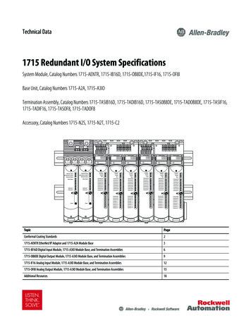
Dranetz Encore Series 61000 Systemxi
xii
CHAPTER 1IntroductionAbout the 61000; Unpacking the 61000; 61000 Accessories; Physical DescriptionAbout the 6100061000descriptionThe Encore Series 61000 System hereinafter referred to as 61000 encompasses twoworld-class data acquisition products developed by Dranetz - the DataNode family ofproducts for the Signature System and the PowerXplorer PX5. This integration ofpower measurement capabilities coupled with an innovative modular design set the61000 apart as a truly revolutionary product. The modular concept applies to both thehardware configuration and firmware architecture allowing the unit to be a multipurpose instrument. 61000 works from being a diagnostic tool to providing preventiveand predictive information as an embedded solution. The instrument is designed tooperate either locally as a stand-alone unit with the optional LCD panel installed or viaremote computer using the Encore Series Software. 61000 is compliant withIEEE1159, IEC61000-4-30 Class A, EN50160 standards, and more. It can be installedin a permanent or semi-permanent installation.Interface to6100061000 can operate locally as a stand-alone unit and/or remotely as a data acquisitionmodule connected to the Encore Series Software:Local operation with optional user interfaceAs a stand-alone unit, the 61000 can be outfitted with optional liquid crystal display(LCD) as user interface. The optional touch screen display is mounted on the frontpanel of the instrument (rack mount or switchgear mount). The LCD panel providesimmediate accessibility to monitoring all measurement parameters and instrumentsetup and configurations. Refer to the 61000 User Interface Operations Guide fordetailed instructions.Remote computer operationThe 61000 can operate as a data acquisition module connected to the Encore SeriesSoftware. This software provides a centralized connection point for remote devices,turning the computer into a self-contained web server. Encore Series Software permitsremote communications with the 61000, with the conventional Internet browser as userinterface. Remote operation includes instrument setup and configurations andmonitoring real-time parameters, disturbance and trend data. Refer to the Encore SeriesSoftware User’s Guide for detailed operating instructions.Datacommunication61000 can communicate data to the Encore Series Software via Ethernet (wired,wireless or fiber-optic based), RS485, and land/cellular modem via RS232. Thephysical modem is an external option and is not included as part of the standardproduct. This extends greater flexibility in the choice of communications interface forremote operation.Continued on next page1-1
About the 61000, continuedInput/Outputmodules61000 provides dedicated digital signal processing power via the separate andindependent connection for each input/output module installed. This modular andconfigurable design shatters the traditional 8-channel (4 voltage, 4 current) instrumentformat. Choose from the voltage, current, and data acquisition modules to build fromone to four instruments in a single, compact, cost-effective format. The availablemodules are: AC Voltage Modules - 4 channels using either terminal block, safety jack, or 25-pinconnector to external voltage pods AC Current Modules - 4 channels for clamp-on CTs or 25-pin connector to externalCT pod Digital Input Modules - 8 channelsNOTE: The Modules are factory-installed. They cannot be installed in the field and arenot user accessible.See Chapter 2 Controls, Indicators and Connectors for more information on the inputmodules. Chapter 3 Circuit Diagrams for Power Monitoring contains wiring diagramsfor when power measurements are to be made.Virtual analyzer At the heart of the 61000 is the virtual analyzer platform or ‘instruments within anplatforminstrument’ configuration. The virtual analyzer allows the instrument to distinguishdata operations in multiple modules. The user can configure up to four virtual analyzersper 61000 instrument.The 61000 firmware architecture is based on the concept of separating the variousstages of acquisition, characterization, communications and visualization with clearlydefined interfaces that decouple one from the other. The instrument can monitor powerquality phenomena for troubleshooting and/or compliance purposes. It can recordinrush conditions, carry out long-term statistical studies to establish performancebaselines, and perform field-based equipment testing and evaluation for commissioningand maintenance. The firmware integrates intuitive instrument setup procedures foreach module analyzer to ensure the capture of all relevant data for additional postprocess analysis, report writing, and data archiving using other compatible Dranetzsoftware applications such as PQView .This guideThis guide is only part of a complete document set designed to provide comprehensiveinformation about the 61000. It primarily contains instructions on how to set up thebasic 61000 hardware for operation. It describes the input module interface and thewiring configurations possible for voltage/current connection. It also describes the datacommunication ports available in the backplane of the instrument. An overview on howto set up the 61000 either as a stand-alone unit or as a data acquisition moduleconnected to the Encore Series Software is included in this guide.For operational description using the local LCD panel, refer to the 61000 UserInterface Operations Guide (check with Dranetz for availability).For operational description using remote communications via Encore Series Software,refer to the Encore Series Software User’s Guide.1-2
Chapter 1/ IntroductionUnpacking the 61000UnpackingFor maximum protection against possible shipping damage, the 61000 has been sealedin a two-piece, plastic suspension pack, enclosed within a durable shipping carton.After opening the carton, inspect the contents for possible shipping damage and checkthe carton inventory.Unpack the 61000 from the carton as follows:StepShippingdamageinspectionAction1Remove any remaining literature inside the top of the carton.2Carefully remove the 61000 from its shipping carton.3Remove all accessories inside the carton. Check that the standard (seepage 1-4) and optional accessories (see Appendix A) you ordered areincluded.Visually inspect the 61000 for possible shipping damage. If any damage exists, firstnotify and file an insurance claim with your carrier or underwriter or both. Then notifyDranetz Customer Service Department of your intentions to return the unit. DO NOTreturn the 61000 without prior instructions from Dranetz Customer ServiceDepartment. Dranetz Customer Service Department can be reached at (732) 287-3680or 1-800-372-6832.If the unit must be returned to Dranetz for service or repair, wrap the unit securely inRepacking forreturn shipment heavy packaging material and place in a well padded box or crate to prevent damage.Do not return the 61000 in an unpadded box. Dranetz will not be responsible fordamage incurred during transit due to inadequate packing on your part.Return noticeNotify Dranetz Customer Service of your intention of returning the unit. Do not returnthe unit without prior instructions from Dranetz. Dranetz Customer Service Departmentcan be reached at (732) 287-3680 or 1-800-372-6832.1-3
61000 Accessories61000 AccessoriesStandardaccessoriesThe standard accessory included with the 61000 is the Encore Series 61000 SystemInstallation Guide, P/N UG-61000.OptionalaccessoriesRefer to Appendix A for the list of hardware and software optional accessoriesavailable for use with 61000. The unit mainframe can be custom-built with optionalinput module connectors, communication port connectors, GPS antenna connector, anda 12V dc power input jack.TechnicalspecificationsSpecifications for the 61000 measured parameters, computed parameters, voltagemodules, current probes, and pod accessories are listed in Appendix B.External dcpower sourceTo connect to an external dc power source, refer to Appendix C.CalibrationThe recommended calibration interval for this unit is once every 12 months.We recommend that you return the unit to the factory for calibration. If you decide todo so, first contact the Dranetz Customer Service Department to obtain anAuthorization Number.Telephone: (732) 287-3680 or 1-800-372-6832Fax: (732) 248-9240Fill out the Repair/Service Order form enclosed in the shipping carton and ship it alongwith the unit to the Dranetz Repair Department. (If this form is missing, ask theDranetz Customer Service Department for a replacement.)1-4
Chapter 1/ IntroductionPhysical DescriptionDimensionsThe 61000 in the desktop enclosure without the optional LCD panel is a self-containedinstrument weighing 4 pounds and measuring 11.25” width x 3.5” height x 7 3/4”depth.When used with the LCD panel installed in 19” rack, the instrument weighs 5 poundsand has an 8” depth.When used with the LCD panel installed in switchgear mounting enclosure, theinstrument weighs 10 pounds and measures 7” width x 6.5” height x 8” depth.Optional display The optional user interface is a 1/4 VGA LCD panel with touch screen menus for localpaneloperation and configuration.Connector panel The backplane panel consists of industrial grade, voltage/current/pod connectors,communication port connectors, dc input power connector, and power switch. SeeChapter 2 Controls, Indicators and Connectors for description.External dcpower sourceTo connect to an external dc power source, refer to Appendix C.1-5
This page intentionally left blank.1-6
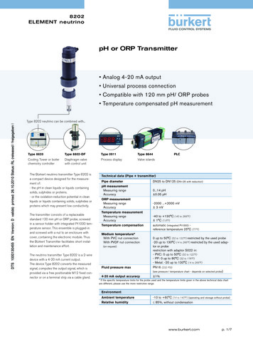
C H A PT ER 2Controls, Indicators, and ConnectorsExternal Components; Connecting to AC Power Source; Communications Interface;Input Module Connectors; Connecting Voltage Measurement Cables; ConnectingCurrent Probes; Connecting Voltage/Current Input Pods; Connecting Digital InputConnectorsExternal ComponentsDescriptionExternal components refer to operator related external controls, indicators andconnectors.Front panelThe 61000 front panel display may look different depending on the enclosure optionsspecified.Front panel without the local LCD User InterfaceSee below for description of the 61000 front display without the LCD user interface.SF-201PartFunction1Status Indicator. LED will light steadily when abnormal condition is detected.The unit is operating normally when light is off.2Monitoring On. LED will light if monitoring is on. Monitoring status is offwhen light is off.3Power Indicator. LED will blink when the unit power switch is turned on. Thenumber of blinks correspond to the number of modules installed.Continued on next page2-1
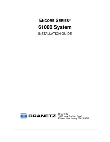
External Components, continuedFront panel(continued)Front panel with the optional LCD User Interface in Rack Mount and SwitchgearMount DisplayThe front view primarily shows the color touch screen LCD. See below for descriptionof the 61000 front display with the LCD panel installed.SF-202dPartFunction1LCD Rack Mount Protective Enclosure with rack handles2Liquid Crystal Display (LCD). Provides 3.75 x 4.75 inches display consistingof 1/4 VGA size screen of text and graphic information. The color LCD isequipped with touch screen technology, operable using the finger and/orstylus. Touch screen display permits menu selection, alpha
employés (ANSI/NFPA 70E-2012) des Etats-Unis et toutes le s conditions de sûreté additionnelles de lieu de travail applicables à votre installation. WARNUNG Der falsche Anschluß dieses Gerätes kann Tod, schwere Verletzungen oder Feuer verursachen. Bevor Sie dieses Instrument anschließen, müssen Sie die Anleitung lesen und verstanden haben.