Transcription
eGate Integrator TutorialRelease 5.0.5SeeBeyond Proprietary and Confidential
The information contained in this document is subject to change and is updated periodically to reflect changes to the applicablesoftware. Although every effort has been made to ensure the accuracy of this document, SeeBeyond Technology Corporation(SeeBeyond) assumes no responsibility for any errors that may appear herein. The software described in this document is furnishedunder a License Agreement and may be used or copied only in accordance with the terms of such License Agreement. Printing,copying, or reproducing this document in any fashion is prohibited except in accordance with the License Agreement. The contentsof this document are designated as being confidential and proprietary; are considered to be trade secrets of SeeBeyond; and may beused only in accordance with the License Agreement, as protected and enforceable by law. SeeBeyond assumes no responsibility forthe use or reliability of its software on platforms that are not supported by SeeBeyond.SeeBeyond, e*Gate, e*Way, and e*Xchange are the registered trademarks of SeeBeyond Technology Corporation in the United Statesand/or select foreign countries. The SeeBeyond logo, SeeBeyond Integrated Composite Application Network Suite, eGate, eWay,eInsight, eVision, eXchange, eView, eIndex, eTL, ePortal, eBAM, and e*Insight are trademarks of SeeBeyond Technology Corporation.The absence of a trademark from this list does not constitute a waiver of SeeBeyond Technology Corporation’s intellectual propertyrights concerning that trademark. This document may contain references to other company, brand, and product names. Thesecompany, brand, and product names are used herein for identification purposes only and may be the trademarks of their respectiveowners. 2004 by SeeBeyond Technology Corporation. All Rights Reserved. This work is protected as an unpublished work under thecopyright laws.This work is confidential and proprietary information of SeeBeyond and must be maintained in strict confidence.Version 20041118160439.eGate Integrator Tutorial2SeeBeyond Proprietary and Confidential
ContentsContentsList of Figures6Chapter 1Introduction10About this Document10What’s in this DocumentIntended AudienceDocument ConventionsScreenshots Used in this Document10111111Related Documents11ICAN Suite Installation Requirements12SeeBeyond Web Site12SeeBeyond Documentation Feedback12Chapter 2Features of the Enterprise Designer13Enterprise Designer Components13Menu Bar14Enterprise Explorer15Project Editor15Chapter 3Building a Project - Scenario116Business Challenge16Project Overview17Project DescriptionProcess OverviewProject Flow Diagram - Scenario1171719ICAN Files Required for the Tutorials20Repository, Logicalhost and EnvironmenteGate Integrator Tutorial203SeeBeyond Proprietary and Confidential
ContentsFile Names20Sample Data20Download the Sample FilesCreate Sample Input XML FileCreate Input (DTD) FileCreate Output (DTD) File20212222Create New Project23Create Connectivity Map25Add Components to the Connectivity Map26Create New Object Type Definition28Configure the Services32Create Service132Apply the Business Rules39Apply the Collaboration46Link Components in the Connectivity Map47Configure the eWays48Multiple records per file (True or False)51Create Environment52Create Environment and Logical Host52Create and Activate Deployment Profile55Run the Bootstrap and Management Agent57Run the Bootstrap58Edit Properties and run bootstrap.bat (method 1)Run Bootstrap.bat from a DOS command (method 2)5859Run Project160Verify Output Data61Edit Input File in Real Time63Chapter 4Building a Project - Scenario264Business Challenge65Project Overview66Required ResourcesProject DescriptionNaming Conventions used in this ScenarioProject Flow Diagram - Scenario266666768Sample Data69Download the Sample FilesCreate Sample Input XML FileCreate Input (DTD) FileCreate Output (DTD) FileeGate Integrator Tutorial696969704SeeBeyond Proprietary and Confidential
ContentsCreate New Project71Create Connectivity Map72Add Components to the Connectivity Map74Add Components to the Connectivity Map74Create New Object Type Definition76Configure Services for Input82Configure svcTimecard to topic82Apply Business Rules for jcdTimecardToTopic collab86Configure Services for Output88Apply Business Rules for jcdTopicToPayrollOut collab92Apply Collaborations and Link ComponentsLink Components in the Connectivity Map103103Configure eWays and JMS Connections105JMS Client Configuration108Create Environment109Create and Activate Deployment Profile111Run Bootstrap and Management Agent114Run prjProject2114Verify Output Data115Chapter 5Enterprise Manager Overview116Browser-based Monitor Console116Locating the Problem NodeUsing Project ViewUsing Environment View116117117Starting and Using Enterprise Manager117Stop ServiceMonitor AlertsCheck Log Messages121122122Glossary124e*Gate 4.x Terms in eGate 5.0127IndexeGate Integrator Tutorial1295SeeBeyond Proprietary and Confidential
List of FiguresList of FiguresFigure 1SeeBeyond Enterprise Designer14Figure 2Enterprise Designer Menu Bar14Figure 3Project Connectivity Map17Figure 4Project Flowchart - Scenario119Figure 5Enterprise Designer Login23Figure 6Create a Project24Figure 7Project Folder: Project124Figure 8Create a Connectivity Map25Figure 9Project1 with a Connectivity Map (CMap1)26Figure 10External Application Selection27Figure 11Connectivity Map27Figure 12OTD Wizard Selection28Figure 13Select DTD Files29Figure 14Select Document Elements30Figure 15Select OTD Options30Figure 16OTD Editor Input31Figure 17Connectivity Map Window32Figure 18New Collaboration Definition (Java) Name33Figure 19New Collaboration Definition Wizard (Java)34Figure 20New Collaboration Web Service Interface35Figure 21Select OTDs36Figure 22Select FileClient OTD37Figure 23Selected OTDs38Figure 24Collaboration Editor (Java)39Figure 25Unmarshal Text40Figure 26Select Unmarshal40Figure 27Business Designer - Unmarshal Text41Figure 28Concatenation Logic42Figure 29Collapse For Loop42Figure 30Source Code Mode43Figure 31Click and Drag s1output44Figure 32Marshal to String44eGate Integrator User’s Guide6SeeBeyond Proprietary and Confidential
List of FiguresFigure 33View Business Rules45Figure 34Write Output File46Figure 35Objects in Connectivity Map47Figure 36Using the Drag and Drop method47Figure 37Connect FileClient to File148Figure 38Connect FileClient to File248Figure 39Inbound eWay49Figure 40External Type Dialog Box49Figure 41Properties Configuration (Inbound eWay)49Figure 42Outbound eWay50Figure 43Properties Configuration (Outbound eWay)51Figure 44Environment with Logicalhost53Figure 45External File Inbound53Figure 46External File Outbound54Figure 47Environment Editor54Figure 48Deployment Profile55Figure 49Environment, Drag and Drop Components56Figure 50Populated Environment57Figure 51Bootstrap Command Example59Figure 52Activation in Progress Message60Figure 53Activation Options60Figure 54Apply Changes in Progress61Figure 55Changes Applied to Logical Host61Figure 56Output File62Figure 57Input File62Figure 58The Relationship Between the Two Systems65Figure 59Project Connectivity Map66Figure 60Project Flowchart - Scenario268Figure 61Enterprise Designer Login Dialog Box71Figure 62Create a Project72Figure 63Project Folder: prjProject272Figure 64Create a Connectivity Map73Figure 65prjProject2 with a Connectivity Map (cmCMap2)74Figure 66External Application Selection75Figure 67Connectivity Map76Figure 68OTD Wizard Selection77Figure 69Select DTD Files78Figure 70Select Document Elements79eGate Integrator User’s Guide7SeeBeyond Proprietary and Confidential
List of FiguresFigure 71Select OTD Options79Figure 72OTD Editor Input80Figure 73Test Input Data File81Figure 74New Collaboration Definition (Java) Name82Figure 75New Collaboration Definition Wizard (Java)83Figure 76New Collaboration Web Service Interface84Figure 77New Collaboration Select OTD85Figure 78Business Rules Designer86Figure 79Methods Dialog Box87Figure 80Send Text Payload87Figure 81New Collaboration Definition Editor (Java)89Figure 82Receive from Topic90Figure 83Input/Output OTDs for jcdTopicToPayrollOut collab91Figure 84Drop Down Arrow button91Figure 85OTDs for jcdTopicToPayrollOut collab92Figure 86Business Rules Designer for jcdTopicToPayrollOut collab93Figure 87Collaboration Editor (Java) - Unmarshal From String94Figure 88Connect Input/Output OTD Nodes95Figure 89Class Browser - parseInt(String s)96Figure 90Window Adjust97Figure 91Prepare for Multiplication97Figure 92Class Browser Constructor98Figure 93Class Browser - toString99Figure 94Multiplication Operation100Figure 95Select a Method100Figure 96Marshal Text101Figure 97Write File Application102Figure 98Unlinked Objects in Connectivity Map103Figure 99Connect Input to Client104Figure 100 Connect JMS to Topic104Figure 101 svcTimecard to topic Linked104Figure 102 Connect Topic to Output105Figure 103 Linked Connectivity Map105Figure 104 Inbound eWay106Figure 105 External Type Dialog Box106Figure 106 Properties Configuration (Inbound eWay)106Figure 107 Directory Data Path107Figure 108 Outbound eWay107eGate Integrator User’s Guide8SeeBeyond Proprietary and Confidential
List of FiguresFigure 109 Properties Configuration (Outbound eWay)108Figure 110 JMS Client Properties Icon108Figure 111 Message Server Configuration109Figure 112 Create Logical Host Servers110Figure 113 External File Inbound111Figure 114 External File Outbound111Figure 115 Deploy Components112Figure 116 Auto Map LogicalHost1113Figure 117 Populated Environment114Figure 118 Output File115Figure 119 Input File115Figure 120 Enterprise Manager Login118Figure 121 Enterprise Manager Home Page118Figure 122 Enterprise Manager Project Explorer119Figure 123 Enterprise Manager Connectivity Map120Figure 124 Runtime Summary120Figure 125 Stop Service121Figure 126 Start Service121Figure 127 Enterprise Manager Alert Messages122Figure 128 Check Logged Messages123eGate Integrator User’s Guide9SeeBeyond Proprietary and Confidential
Chapter 1IntroductionWelcome to the eGate Integrator Tutorial. The Tutorial must be run on a Windows system.The Repository and Logical Host may be installed on any supported platform, but theEnterprise Designer must be installed and run on a Windows computer.This document contains tutorials to help you get started with eGate Integrator. Thesetutorials are very basic and are intended for new eGate users. Sample files are providedalong with the documentation. These tutorials are “end-to-end” scenarios. In doingthese tutorials the user creates, deploys, and runs Projects to produce output which canbe verified.What’s in This Chapter! About this Document on page 10! Related Documents on page 11! ICAN Suite Installation Requirements on page 12! SeeBeyond Web Site on page 12! SeeBeyond Documentation Feedback on page 121.1About this DocumentThis document contains the procedures to complete two scenarios that demonstratesome of the basics of the eGate Integrator product. You can use the sample dataprovided to go through these two scenarios and learn the basics fast.1.1.1What’s in this Document! Chapter 1 “Introduction” overviews the contents of the eGate Integrator Tutorial,describes the writing conventions used in this document, and provides a completelist of related eGate Integrator documentation.! Chapter 2 “Features of the Enterprise Designer” introduces the EnterpriseDesigner Components, Menu Bar, Enterprise Explorer, and Project Editor.! Chapter 3 “Building a Project - Scenario1” provides a simple “end-to-end”scenario where you perform a data concatenation.! Chapter 4 “Building a Project - Scenario2” provides an “end-to-end” scenariowhere you perform data transformation, involving a multiplication operation.eGate Integrator Tutorial10SeeBeyond Proprietary and Confidential
Chapter 1IntroductionSection 1.2Related Documents! Chapter 5 “Enterprise Manager Overview” provides an overview of the EnterpriseManager which is used to view and monitor projects dynamically.! “Glossary”.! “Index”.1.1.2Intended AudienceThis guide is intended for experienced computer users who have the responsibility ofhelping to set up and maintain a fully functioning ICAN Suite system. This personmust also understand any operating systems on which will be installed , and must bethoroughly familiar with Windows-style GUI operations.1.1.3Document ConventionsThe following conventions are observed throughout this document.Table 1 Document ConventionsTextConventionExampleNames of buttons, files,icons, parameters, variables,methods, menus, and objectsBold text!!!!!!Command line arguments,code samplesFixed font. Variables areshown in bold italic.bootstrap -p passwordHypertext linksBlue textSee “Document Conventions” onpage 11Hypertext links for Webaddresses (URLs) or emailaddressesBlue underlined com1.1.4Click OK to save and close.From the File menu, select Exit.Select the logicalhost.exe file.Enter the timeout value.Use the getClassName() method.Configure the Inbound File eWay.Screenshots Used in this DocumentThe screenshots in this document should be current with the product release shown onthe title page of this document. Depending on what you have installed, it is possiblethat some of your screens could look slightly different than some screenshots in thisdocument.1.2Related DocumentsThe following SeeBeyond documents provide additional information about eGateIntegrator:eGate Integrator Tutorial11SeeBeyond Proprietary and Confidential
Chapter 1IntroductionSection 1.3ICAN Suite Installation Requirements! SeeBeyond ICAN Suite Installation Guide! eGate Integrator System Administration Guide! eGate Integrator Release Notes! eGate Integrator User’s Guide! SeeBeyond ICAN Suite Primer1.3ICAN Suite Installation RequirementsTo simplify these examples, this tutorial assumes you have all of the following eGatecomponents installed on a single Windows system:! eGate Repository! Logical Host! Enterprise Designer! eGate product! File eWay productRefer to the SeeBeyond ICAN Suite Installation Guide for system requirements andinstallation instructions. See also: Chapter 3, ICAN Files Required for the Tutorials onpage 20.1.4SeeBeyond Web SiteThe SeeBeyond Web site is your best source for up-to-the-minute product news andtechnical support information. The site’s URL is:http://www.seebeyond.com1.5SeeBeyond Documentation FeedbackWe appreciate your feedback. Please send any comments or suggestions regarding thisdocument to:docfeedback@seebeyond.comeGate Integrator Tutorial12SeeBeyond Proprietary and Confidential
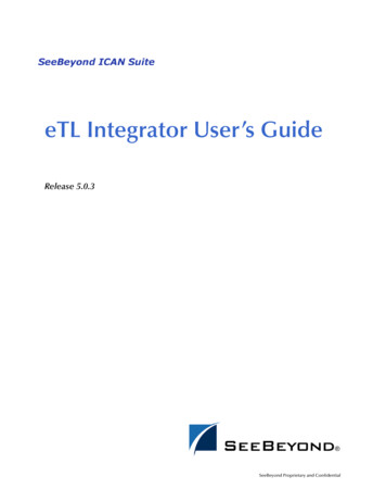
Chapter 2Features of the Enterprise DesignerThe Enterprise Designer is the graphical user interface (GUI) used to design andimplement ICAN 5.0 projects. This chapter overviews the features and interface of theEnterprise Designer window.What’s in This Chapter! Enterprise Designer Components on page 13! Menu Bar on page 14! Enterprise Explorer on page 15! Project Editor on page 152.1Enterprise Designer ComponentsThe Enterprise Designer is used to create and configure the components of an eGateProject. Each component of this interface is identified in Figure 1.eGate Integrator Tutorial13SeeBeyond Proprietary and Confidential
Chapter 2Features of the Enterprise DesignerSection 2.2Menu BarFigure 1 SeeBeyond Enterprise DesignerMenu BarToolbarYou will create your Connectivity Map in this pane.You will also create your Business Rules in this pane.Enterprise ExplorerProject EditorNote: This chapter provides a high-level overview of the Enterprise Designer GUI. Refer tothe eGate Integrator User’s Guide for a more detailed description of the menu bar,toolbar, Enterprise Explorer, and Enterprise Designer.2.2Menu BarThe menu bar shown below in Figure 2 provides access to a series of menu commandsused to build and manage a Project.Figure 2 Enterprise Designer Menu BarThe function of each menu is briefly described below:! File—Lists options for save, save all, and exit.! Tools—Lists options for Impact Analyzer, Update Center and Setup Options.! View—Lists options to view the Environment Explorer and Project Explorer.! Window—Lists options for the various window displays, cascade, tile, etc.! Help—online help for all installed moduleseGate Integrator Tutorial14SeeBeyond Proprietary and Confidential
Chapter 2Features of the Enterprise Designer2.3Section 2.3Enterprise ExplorerEnterprise ExplorerThe Enterprise Explorer organizes all of the components of a Project into a series offolders and contains the following two tabs:! Project Explorer—Logical configurations designed to help solve a businessproblem. This branch includes all the components of an Enterprise Designer Project,including Connectivity Maps, Services, Object Type Definitions (OTD), andDeployment Profiles.! Environment Explorer—Collections of logical hosts and external systems capableof hosting eGate components and information about external systems, which maybe involved with an eGate configuration. You will go into the EnvironmentExplorer when you are ready to deploy and run your project.2.4Project EditorThe Project Editor is where you use GUI tools (or even enter code directly) to create aProject. This part of the Enterprise Designer is empty when you start a new Project.However, as you work through the tutorial, the Project Editor quickly fills withcomponents and graphical structures representing the various stages of the Project. Thetypes of windows in the Project Editor area include:! Connectivity Map—Contains business logic components, such as Services, Topics,queues, and eWays, that you include in the structure of a Project.! Collaboration Editor (Java)—Contains the business rules defined in Java.! Collaboration Editor (XSLT)—Contains the business rules defined in XSLT.! OTD Editor—Edits and tests the OTDs (Object Type Definitions)! Deployment Profile Editor—Edits the deployment profile! Environment—Collection of physical resources (logical hosts and external systems)eGate Integrator Tutorial15SeeBeyond Proprietary and Confidential
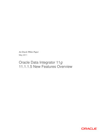
Chapter 3Building a Project - Scenario1This Tutorial provides step-by-step procedures for creating and testing an eGateProject. This Project addresses a very simple business challenge where an inputTimeCard file is read and a workfile is output.What’s in This Chapter! Business Challenge on page 16! Project Overview on page 17! ICAN Files Required for the Tutorials on page 20! Sample Data on page 20! Create New Project on page 23! Create Connectivity Map on page 25! Add Components to the Connectivity Map on page 26! Create New Object Type Definition on page 28! Configure the Services on page 32! Link Components in the Connectivity Map on page 47! Configure the eWays on page 48! Create Environment on page 52! Run the Bootstrap and Management Agent on page 57! Verify Output Data on page 613.1Business ChallengeThe Project described in this chapter provides a solution to the following businesschallenge:In this very simple scenario FirstName and LastName from the input file areconcatenated into the field FullName in the output file. JobTitle, HoursWorked andRate are disregarded in Scenario1.! The input data in this system is in XML format with six fields: EmployeeNumber,LastName, FirstName, JobTitle, HoursWorked, and Rate.eGate Integrator Tutorial16SeeBeyond Proprietary and Confidential
Chapter 3Building a Project - Scenario1Section 3.2Project Overview! The output workfile in XML format contains the following fields: FullName, andEmpNo.3.2Project OverviewCreate a basic eGate Project to meet the business challenge described in “BusinessChallenge” on page 16.3.2.1Project DescriptionThe finished eGate Project contains components used to move the data throughout theProject and publish the data in the appropriate format for the output workfile.Figure 3 Project Connectivity MapFile1Inbound eWayService1Outbound eWayFile2These components perform the following functions:! File1: The Input file External Application contains the Input XML data file.! Inbound eWay: The inbound eWay polls a specified location on the file system forthe input XML data file.! Service1: This Service performs a concatenation of the name fields.! Outbound eWay: This eWay publishes the finished output data to the file system inthe format appropriate for the output work file.! File2: This is the output work file.3.2.2Process OverviewComplete the following general steps:1 “Sample Data” on page 202 “Create New Project” on page 233 “Create Connectivity Map” on page 254 “Add Components to the Connectivity Map” on page 265 “Create New Object Type Definition” on page 286 “Configure the Services” on page 32eGate Integrator Tutorial17SeeBeyond Proprietary and Confidential
Chapter 3Building a Project - Scenario1Section 3.2Project Overview7 “Apply the Business Rules” on page 398 “Apply the Collaboration” on page 469 “Configure the eWays” on page 4810 “Create Environment” on page 5211 “Run the Bootstrap and Management Agent” on page 5712 “Verify Output Data” on page 61eGate Integrator Tutorial18SeeBeyond Proprietary and Confidential
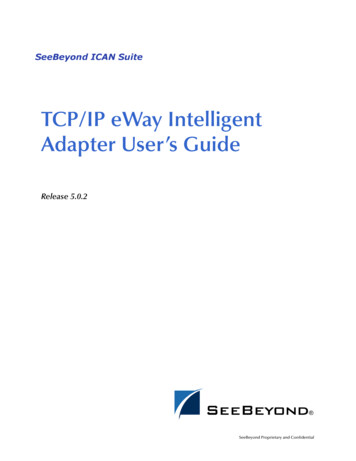
Chapter 3Building a Project - Scenario13.2.3Section 3.2Project OverviewProject Flow Diagram - Scenario1Figure 4 Project Flowchart - Scenario1Obtain Sample DataCreate a New ProjectAdd Components to aConnectivity MapCreate New Object TypeDefinitions (OTDs)Create and Configure Servicesand CollaborationsLink Components in theConnectivity MapConfigure eWays and JMSConnectionsCreate an EnvironmentActivate the Deployment ProfileRun the Bootstrap andManagement AgentVerify Output DataeGate Integrator Tutorial19SeeBeyond Proprietary and Confidential
Chapter 3Building a Project - Scenario13.3Section 3.3ICAN Files Required for the TutorialsICAN Files Required for the TutorialsPlease refer to the SeeBeyond ICAN Suite Installation Guide for instructions aboutuploading files to the Repository. The following files are required to run the tutorials:! License.sar! eGate.sar! ProductManifest.xml! FileeWay.sar! eGateDocs.sar (PDF and sample files)The Tutorial assumes the software is installed in C:\ican50. Your installation may bedifferent.Although not required for the Enterprise Manager, you will have more features for GUIdisplays if you use the SVG Viewer. Use the EnterpriseManager-PluginWin98ToXP.sar (required for the Adobe SVG Viewer plug-in for Windows). EnterpriseManager is not required for the tutorials.3.3.1Repository, Logicalhost and EnvironmentYou may use the same Repository, Logicalhost and Environment for both tutorials,Scenario1 and Scenario2. You should use different names for the deployments.Scenario1 should be deployed as Deployment1 and Scenario2 should be deployed asDeployment2.3.3.2File NamesThe file names used in Scenario1 (Project1) should be different than the file names usedin Scenario2 (Project2). See the following section, Sample Data.3.4Sample DataThis Project uses the sample files found in the Project1 folder of the eGate TutorialSample that you download using the steps below. The files used in Scenario1 are:s1input multiple.dtd, s1output multiple.dtd, and TimeCard-Multiple.xml. (The “s1”in the file names stands for Scenario1.)3.4.1Download the Sample FilesUse the Sample Files1 Logon to the Enterprise Manager.2 Click the Documentation tab.eGate Integrator Tutorial20SeeBeyond Proprietary and Confidential
Chapter 3Building a Project - Scenario1Section 3.4Sample Data3 Click eGate Integrator.4 Double-click and save the eGate Tutorial Sample Files.Note: You can also create the files you need. See sections 3.4.2, 3.4.3, and 3.4.4 below, butthis shouldn’t be necessary.3.4.2Create Sample Input XML FileUse a text editor such as Microsoft Notepad to create the input XML file. You can alsocopy and paste from this document (PDF) using the text select tool from within AdobeAcrobat.Create XML fileYour XML file should look similar to the structure and syntax below. In this scenario ofthe Tutorial there are four records. ?xml version "1.0" encoding "UTF-8" ? Employees Employee EmployeeNumber 100 /EmployeeNumber LastName Smith /LastName FirstName Jane /FirstName JobTitle Manager /JobTitle HoursWorked 40 /HoursWorked Rate 55 /Rate /Employee Employee EmployeeNumber 123 /EmployeeNumber LastName Chang /LastName FirstName Ling /FirstName JobTitle Manager /JobTitle HoursWorked 40 /HoursWorked Rate 60 /Rate /Employee Employee EmployeeNumber 118 /EmployeeNumber LastName Jamison /LastName FirstName Dick /FirstName JobTitle Clerk /JobTitle HoursWorked 40 /HoursWorked Rate 22 /Rate /Employee Employee EmployeeNumber 144 /EmployeeNumber LastName Nakayama /LastName FirstName Takeshi /FirstName JobTitle Supervisor /JobTitle HoursWorked 40 /HoursWorked Rate 35 /Rate /Employee /Employees 1 In Windows Explorer, create a directory for the data files. For this scenario, usec:\eGateData\Project1.2 In Notepad, create an XML file containing the data shown above.3 Save the file as TimeCard Multiple.xml in the c:\eGateData\Project1 directory.eGate Integrator Tutorial21SeeBeyond Proprietary and Confidential
Chapter 3Building a Project - Scenario13.4.3Section 3.4Sample DataCreate Input (DTD) FileThe s1input multiple.dtd file is used as a representation of the data in the TimeCardsystem.The s1input multiple.dtd file uses the following elements:! EmployeeNumber! LastName! FirstName! JobTitle! HoursWorked! RateCreate Input (DTD) FileYour input (DTD) should look similar to the structure and syntax below.1 In Notepad, create an XML file containing the following information: ?xml version "1.0" encoding "UTF-8"? !ELEMENT Employees(Employee ) !ELEMENT Employee(EmployeeNumber, LastName, FirstName, JobTitle,HoursWorked, Rate) !ELEMENT EmployeeNumber(#PCDATA) !ELEMENT LastName(#PCDATA) !ELEMENT FirstName(#PCDATA) !ELEMENT JobTitle(#PCDATA) !ELEMENT HoursWorked(#PCDATA) !ELEMENT Rate (#PCDATA) 2 Save the file as s1input multiple.dtd in the c:\eGateData\Project1 directory.3.4.4Create Output (DTD) FileThe s1output multiple.dtd file is used as a representation of the data in the outputworkfile.The s1output multiple.dtd file uses the following elements:! FullName! EmpNoCreate Output (DTD) fileYour output (DTD) should look similar to the structure and syntax below.1 In Notepad, create an XML file containing the following information: ?xml version "1.0" encoding "UTF-8"? !ELEMENT Employees(Employee ) !ELEMENT Employee(FullName, EmpNo) !ELEMENT FullName(#PCDATA) !ELEMENT EmpNo(#PCDATA) 2 Save the file as s1output multiple.dtd in the c:\eGateData\Project1 directory.eGate Integrator Tutorial22SeeBeyond Proprietary and Confidential
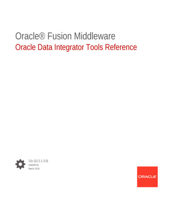
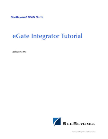
Chapter 3Building a Project - Scenario13.5Section 3.5Create New ProjectCreate New ProjectThere are many ways to create a Project and link the modules. This Tutorial presentsone scenario. Begin by creating and naming a Project in the Enterprise Designer.Start Enterprise DesignerStart the Enterprise Designer according to your organization’s instructions.1 Start the Enterprise Designer by executing runed.bat in your ican50 folder, forexample: (c:\ican50\edesigner\bin).The Enterprise Designer Login dialog box appears.Figure 5 Enterprise Designer Login2 Type your Login ID and Password. Click Login to start the Enterprise Designer.The Repository URL value will default to the localhost information you suppliedwhen you downloaded the Enterprise Designer, i.e. http:// localhost :12000/Repository tutorial.Note: If your login window doesn’t appear or if you get an invalid Username or Passworderror, make sure your Repository is running. Also, be aware that the Username andPassword are case sensitive.eGate Integrator Tutorial23SeeBeyond Proprietary and Confidential
Chapter 3Building a Project - Scenario1Section 3.5Create New ProjectCreate ProjectA Project is a collection of logical components, configurations, and files that are used tosolve a business problem.1 In the Enterprise Explorer pane of the Enterprise Designer, right-click theRepository name (computer icon). Click New Project.Figure 6 Create a Project2 Accept the default Project1 as the file name and press Enter.3 The Project1 appears in the Explorer pane on the left side of the window.Figure 7 Project Folder: Project1eGate Integrator Tutorial24SeeBeyond Proprietary and Confidential
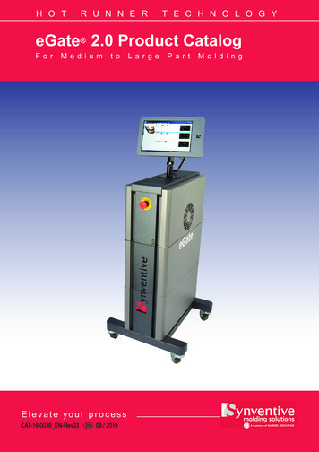
Chapter 3Building a Project - Scenario13.6Section 3.6Create Connectivity MapCreate Connectivity MapProject1 needs a Connectivity Map to define the flow between the TimeCard systemand the work file output.This section describes how to create the Connectivity Map for Project1.Name Connectivity MapA Connectivity Map contains business logic and routing information about the datatransmission. The Connectivity Map is a GUI (graphical representation) of the project.1 In the Enterprise Explorer, right-click the Project1 icon. Click New andConnectivity Map.Figure 8 Create a Connectivity Map2 You may give your Connectivity Map a name. In this Tutorial, accept the defaultname, CMap1.CMap1 is added to your Project1, as shown in the following figure.eGate Integrator Tutorial25SeeBeyond Proprietary and Confidential
Chapter 3Building a Project - Scenario1Section 3.6Create Connectivity MapFigure 9 Project1 with a Connectivity Map (CMap1)External ApplicationQueueTopicWeb Services ClientCollapse or expandProject nodeServiceNote: The CMap1 Connectivity Map appears as an icon in the Project Explorer. ACMap1 tab is also added at the bottom of the Connectivity Map.3.6.1Add Components to the Connectivity MapIn this section, add the components to the Connectivity Map. Later link the componentsas shown in Figure 3 on page 17.In this section, add the following components to the Connectivity Map:! File1 (File External Application)! Service1! File2 (File External Application)Populate Connectivity MapPlace an input file (External Application) in your Connectivity Map.1 On the Connectivity Map
Welcome to the eGate Integrator Tutorial. The Tutorial must be run on a Windows system. The Repository and Logical Host may be installed on any supported platform, but the Enterprise Designer must be installed and run on a Windows computer. This document contains tutorials to help you get started with eGate Integrator. These