Transcription
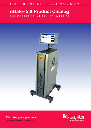
H O TR U N N E RT E C H N O L O G YeGate 2.0 Product CatalogForM e d iumtoElevate your processCAT-16-0039 EN-Rev03EN09 / 2019La r g ePa r tM o l d i n g
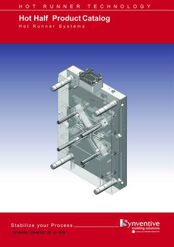
HOTRUNNERTECHNOLOGYeGate Electric Valve GateIllustrations simplified, schematically drawn and not to scale. All dimensions in mm.Product DescriptioneGate Hot Runner SystemPatented electronically actuated Valve Gatesystem that provides precise pin position andvelocity control.A) Electric Actuator*B) eGate Junction Box*C) Power/Sensor Cable from Drive Box toeGate Junction BoxD) Power Cable from Controller to Drive Box- 1 required per 8-zonesE) Digital Communication Cable fromController to Drive BoxF) ControllerG) Removable Tablet with preloadedeShop Software(included with Controller)H) Controller-Injection Molding MachineInterface CableI) IMM InterfaceJ) Drive Box* Tool EquipmentOperation Principle Linear Electric Actuator with electronicallycontrolled open/close and motion/positionprofile. Variable opening stroke length, intermediate closing position and opening/closingspeed of each valve pin. High precision, individual pin position,repeatable to within 0.01 mm increments.Areas of Application: Applications with hydraulic or electricInjection Molding Machines and/or cleanroom environments Optimizing balance in multi-cavity andfamily molding Optimizing surface quality of sequential orcascade injection molding Improved dimensional control on injectionmolded parts Reduce cavity pack pressures Pre-fill cold runnersNOTEeGate functionality requires an interfaceon the customers Injection Molding Machineaccording to Synventive specifications.Master Language is English 2019 Synventive Molding SolutionsCAT-16-0039 EN-REV03-2-For a specific application, please consult SynventiveAll rights reserved. Errors and omissions excepted
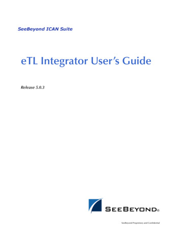
HOTRUNNERTECHNOLOGYeGate Electric Actuator AssemblyIllustrations simplified, schematically drawn and not to scale. All dimensions in mm.Electric Actuator AssemblyELA761602M0#Actively-cooled Electric Actuator Assemblythat is bolted onto the manifold. The ElectricActuator Assembly has pre-terminated cableconnections for easy installation to the eGate Junction Box. Available cable length configurations:# 1, 3, 6(1m, 3m, 6m long cable configurations)The Electric Actuator Assembly includes 2main sub-assemblies:ELA7616-#000: Electric Linear Servo MotorLCA-02: Linear Motion ConverterELA7616-WJA-01: Cooling JacketThe Electric Servo Motor includes an integrated Thermal Switch, which sends a signalto the Controller that automatically shuts downthe Motor if overheated beyond 130 C.Technical DataValve Gating typeCylindrical Gate andTapered GateAttachmentQuick Coupling,anti-rotationAdjustment /-1.5 mm, 0,01 mmincrementsValve Pin Dia.5, 6, & 8 mmMax. Speed80 mm/secMax. Pressure2070 bar (30.000 psi)Max. Hot RunnerTemperature315 C (600 F)Nominal Stroke16 mmCooling Connection M10x1CoolingThe passive plate between the Actuator andthe manifold provides indirect active cooling ofthe needle guide via the Cooling Jacket on theActuator to thermally separate it from the hotmanifold surface.The Electric Actuator is actively cooled with aCooling Jacket.A maximum of three Actuators can be plumbedin series to create an independent coolingcircuit to prevent overheating of the Actuators.Maximum temperature of each cooling circuitis 35 C / 95 F.20 minute Post-Cooling required for applications processing at temperatures greater than280 C / 535 FMaster Language is English 2019 Synventive Molding SolutionsCAT-16-0039 EN-REV03-3-For a specific application, please consult SynventiveAll rights reserved. Errors and omissions excepted
HOTRUNNERTECHNOLOGYeGate Electric ActuatorIllustrations simplified, schematically drawn and not to scale. All dimensions in mm.Cutout DimensionsCutout dimensions are provided for referenceas a guide to determine basic requirements.Reference system drawings for actual dimensions.Pitch DimensionsPitch dimensions are provided for referenceas a guide to determine minimum basicrequirements. Consult Synventive for applications requiring tighter pitches.Master Language is English 2019 Synventive Molding SolutionsCAT-16-0039 EN-REV03-4-For a specific application, please consult SynventiveAll rights reserved. Errors and omissions excepted
HOTRUNNERTECHNOLOGYeGate eGate Junction BoxIllustrations simplified, schematically drawn and not to scale. All dimensions in mm.eGate Junction BoxSince eGate Hot Runner Systems aresupplied pre-wired and pre-plumbed with acustomized wireguard, the eGate JunctionBox is mounted to the Synventive wireguard.The connections on the Junction Box includethe motor power, sensor and encoder signallines.The eGate Junction Box is available in8-zone and 16-zone configurations.In order to ensure Actuator Connectors do notinterfere with other mold components, pleaseensure a minimum installation space according to the illustrations.ELA2-08LJB-01 (8-zone Junction Box)#ELA2-16LJB-01 (16-zone Junction Box)#Master Language is English 2019 Synventive Molding SolutionsCAT-16-0039 EN-REV03-5-For a specific application, please consult SynventiveAll rights reserved. Errors and omissions excepted
HOTRUNNERTECHNOLOGYeGate Drive BoxIllustrations simplified, schematically drawn and not to scale. All dimensions in mm.eGate Drive BoxThe Drive Box provides Digital Control ofeGate Electric Actuators. The Drive Box actsas the interface between the Controller andeGate Junction Box that feeds electricity intothe motor in varying amounts and at varyingfrequencies, thereby indirectly controlling themotor’s speed and current (torque).The Drive Box is designed to be ideallymounted on the Injection Molding Machine(ideally near Top Operator side) via four M10Socket Head Cap Screws. Consult Synventiveprior to finalizing mounting ne)Two Drive Boxes are required for any application requiring more than 8 Electric Actuators.In this configuration: The Communication Port from each DriveBox would be daisy-chained. Each Drive Box Power/Sensor Cablewould be connected to the applicableeGate Junction Box.ELA2-LDRVBOX06(6-Zone) Each Drive Box Main Power Cable wouldbe connected to the applicable PowerConnector on the eGate Controller. One 8-zone Drive Box plus applicable2, 4, 6, or 8-zone Drive Box would beprovided under the following part numbersas needed: ELA2-LDRVBOX10 ELA2-LDRVBOX12 ELA2-LDRVBOX14 one)(14-Zone)(16-Zone)NOTEThe Drive Boxes can be mounted eitherhorizontal or vertical orientations.Master Language is English 2019 Synventive Molding SolutionsCAT-16-0039 EN-REV03-6-For a specific application, please consult SynventiveAll rights reserved. Errors and omissions excepted
HOTRUNNERTECHNOLOGYeGate Controller#Illustrations simplified, schematically drawn and not to scale. All dimensions in mm.eGate ControllerThe Controller is available in 8-zone and16-zone configurations, which include a Tabletwith pre-installed eShop Software. The Tabletcan be removed from Controller Cabinet andmounted on the Injection Molding Machine viaMagnets included on the back of the TabletEnclosure.Each Controller allows up to 2 additional analoginputs per zone in order to monitor and/or trigger valve pin movements based upon a sensedcondition (such as pressure).Optional Controller versions to trigger valve pinmovements via Priamus Sensors by interfacingwith Priamus FILLCONTROL is also available.1) 8-Zone eGate ControllerThe eGate Controller can be used to controlup to 8 Electric Actuators.ELA2-08ZC02ELA2-08ZC02P (with Priamus Triggering)Technical DataCurrent220-240 V AC1 Phase / N / PE50 / 60 Hz20 A (10 A when runningup to 4 zones)Temperature0 . 43 CHumidity 95%No condensation2) 16-Zone eGate ControllerThe eGate Controller can be used to controlup to 16 Electric Actuators.ELA2-16ZC02ELA2-16ZC02P (with Priamus Triggering)Technical DataCurrent220-240 V AC1 Phase / N / PE50 / 60 Hz40 A (30 A when runningup to 12 zones)Temperature0 . 43 CHumidity 95%No condensationMaster Language is English 2019 Synventive Molding SolutionsCAT-16-0039 EN-REV03-7-For a specific application, please consult SynventiveAll rights reserved. Errors and omissions excepted
HOTRUNNERTECHNOLOGYeGate CablesIllustrations simplified, schematically drawn and not to scale. All dimensions in mm.eGate Cables1) Junction Box to Drive Box 2 m long)(5 m long)(8 m long)(15 m long)2) Controller to Drive Box 1504(2 m long)(5 m long)(8 m long)(15 m long)3) Controller to Drive Box DigitalCommunication CableTRG502-T4T-1m (1 m long)TRG502-T4T-5m (5 m long)TRG502-T4T-10m (10 m long)4) Controller to IMM CableELAIMMC4572-03 (4.6 m long)ELAIMMC7620-03 (7.6 m long)ELAIMMC15000-03 (15 m long)5) Controller to Tablet CableELA-UIC01-01 (1 m long)ELA-UIC08-01 (8 m long)ELA-UIC15-01 (15 m long)Controller KitsELA2-08ZC02-K01 (8-zone)ELA2-16ZC02-K01 (16-zone)ELA2-08ZC02P-K01(8-zone, with Priamus triggering)ELA2-16ZC02P-K01(16-zone, with Priamus triggering)The above Controller Kit part numbersinclude the following cable lengths: Junction Box-to- Drive Box Cable(5 m) Controller-to-Drive Box PowerCable (8 m) Controller-to-Drive Box DigitalCommunication Cable (10 m) Controller-to-IMM Cable (7.6 m) Controller-to-Tablet Cable(1 m, included with Controller)Master Language is English 2019 Synventive Molding SolutionsCAT-16-0039 EN-REV03-8-For a specific application, please consult SynventiveAll rights reserved. Errors and omissions excepted
HOTRUNNERTECHNOLOGYeGate IMM Controller Interface KitIllustrations simplified, schematically drawn and not to scale. All dimensions in mm.eGate IMM Interface Kit(ELAIMMCK04)The eGate IMM Kit is used to establish aconnection between the Injection MoldingMachine (IMM) and the eGate ControlUnit.1. eGate Face Plate AssemblyThe Face Plate assembly is installed onthe operator side of the injection moldingmachine. It represents the interface between the IMM and eGate Control Unit.a) Status LED Yellow indicate IMM modeb) Interface Mode Switchc) Status LED Green indicates eGate moded) Interface ConnectorThe Face Plate assembly is supplied as part ofthe eGate IMM Interface Kit ELAIMMCK04.NOTEThe Interface Kit ELAIMMCK04 MUST be installed PRIOR TO the mold trial with eGate .Customer is responsible for coordinating thisinstallation with the IMM manufacturer.2. IMM Relay BoxThe IMM interface connector is a selfcontained opto-isolated circuit that isinterfaced to the IMM signals requiredto properly sequence the actuators andhandle all of the safety related interlocks. Allsignals work on 24V.The IMM Relay Box is mounted inside theIMM cabinet. The signals from the IMM arewired directly to the provided terminal strip.3. Face Plate to Relay Box Cable Theprovided 5ft DB26 male-to-male cable isused to connect the Face Plate to the RelayBox. Standard length: 1.5 m4. “Controller Injection MachineInterface Wiring Instructions”SVC-16-0039 EN-Rev##Master Language is English 2019 Synventive Molding SolutionsCAT-16-0039 EN-REV03-9-For a specific application, please consult SynventiveAll rights reserved. Errors and omissions excepted
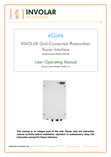
HOTRUNNERTECHNOLOGYeGate IMM Interface TesterIllustrations simplified, schematically drawn and not to scale. All dimensions in mm.1. IMM Interface Tester(ELAIMMTK01)The eGate IMM Interface Tester Kit is usedto check the Injection Molding MachineInterface prior to the installation of theeGate Systems. These signals must betested prior to Mold Trials.eGate IMM Interface TesterThe eGate IMM Interface Tester is used toconfirm that the wiring of the implementedinterface is correct and all signals are working. Contact Synventive Customer Servicefor information regarding the tester.1 2 3 4 5 1Emergency Stop2Restart3Safety Gates7 4Mold Closed5Temperature Set Point8 6Screw Forward 17Screw Forward 2 for two shotand co-injection applications.8Screw Forward 3for three shot applications.9Error Signal Output10Injection Inhibit Output11Set Mode Switch Up12LED Test Switch DOWN6 129 10 112. ConnectorseGate IMM Interface TestereGate IMM Connector Cable*eGate IMM Face Plate ConnectorFace Plate AssemblyInterface between IMM and eGate Control Unit.Master Language is English 2019 Synventive Molding SolutionsCAT-16-0039 EN-REV03-10-For a specific application, please consult SynventiveAll rights reserved. Errors and omissions excepted
www.synventive.comThe AmericasSynventive Molding Solutions Inc.10 Centennial DrivePeabody, MA 01960, USATel.: 1 978 750 8065Fax: 1 978 646 3600E-Mail: info@synventive.comEuropeSynventive Molding Solutions GmbHHeimrodstr. 1064625 Bensheim, GermanyTel.: 49 (0) 6251 / 9332-0Fax: 49 (0) 6251 / 9332-90E-Mail: infohrde@synventive.comAsiaSynventive Molding Solutions (Suzhou) Co.Ltd.12B Gang Tian Industrial SquareSuzhou Industrial Park, China 215021Tel.: 86 512 6283 8870Fax: 86 512 6283 8890E-Mail: infohrcn@synventive.comCAT-16-0039 EN-REV03 2019-09-05 2019 Synventive Molding SolutionsDTP: KA
machine. It represents the interface be-tween the IMM and eGate Control Unit. a) Status LED Yellow indicate IMM mode b) Interface Mode Switch c) Status LED Green indicates eGate mode d) Interface Connector The Face Plate assembly is supplied as part of . the eGate IMM Interface Kit ELAIMMCK04. NOTE. The Interface Kit ELAIMMCK04 MUST be in-