Transcription
OPERATOR’SMANUAL & PARTS LISTAERA-vatorMODEL AE40LFIRST PRODUCTS INC.164 Oakridge Church Rd.Tifton, Georgia 31794 U.S.A.Phone (229) 382-47681-800-363-8780Fax (229) 382-0506Web: www.1stproducts.com Email: Sales@1stproducts.comSer. 352 thru 434Printed in U.S.A.PBREV0104
INTRODUCTIONThank you for purchasing an AREA-vator. This piece of equipment has been carefully engineered and manufactured to provide years of reliable service.The AERA-vator is one of the most unique and versatile pieces of equipment on the markettoday. It is designed for the practices of turf cultivation, seed bed preparation, and bare soilconditioning in your toughest soils.We recommend that you carefully read the owners and operators manual prior to operation.Also ensure that all future operators read this manual and become fully trained before allowingthem to use or maintain this equipment. Time spent becoming acquainted with the safe operation, performance, and maintenance of the AERA-vator will add longer life and greater satisfaction to your new purchase.This machine is designed with safety in mind. However, if the machine is handled carelesslyand not as instructed it can be a dangerous piece of equipment. Observe all safety informationin this manual and decals on the equipment. You the operator are responsible when operatingthis equipment.The illustrations and data used in the manual were current at time of printing. The manufacturer reserves the right to make changes or add improvements to its products at any time without incurring any obligation to make such changes to products manufactured previously.REMEMBER SAFETY IS ALWAYS FIRST !ATTENTION: Read and understand the instructions and warnings carefully before using this machine. Read the warranty located on page 16. Fill in the required information on the warranty registration provided and return to the address on the front of this manual.The warranty registration must be returned to validate warranty.1
TABLE OF CONTENTSSAFETY SYMBOLS .3SAFETY DECALS .4OPERATION SAFETY .5OPERATOR INSTRUCTIONS .6UNDERSTANDING HOW THE SWING HITCH OPERATES (PRIOR TO HITCHING TOTRACTOR) .7CORRECTLY ADJUSTING THE HITCH TO THE TRACTOR .7PRE-OPERATION CHECK LIST.8MAINTENANCE SAFETY.9OPERATOR MAINTENANCE.10AE40L SERVICE INSTRUCTIONS.11ROTOR SHAFT.11I. Removal & Disassembly (Clean the machine thoroughly with a pressure washer). 11II.Reassembly and Installation . 12TINE REPLACEMENT.14SEEDER MAINTENANCE.14SEEDER CALIBRATION .15I. GENERAL OBSERVATIONS . 15II.CALIBRATION PROCEDURE. 16WARRANTY INFORMATION .17MAIN FRAME ASSEMBLY .17DRIVE TRAIN COMPONENTS.18LIFT AND TRAIL HITCH GROUP.19ROTOR ASSEMBLY .20DRIVE LINE COMPONENTS.21SMOOTHING ROLLER.22GROOMING RAKE & BRUSH.2340l SEEDER MOUNTING .2442” SEEDER DRIVE .2542” SEEDER PARTS LIST .2642” SEEDER .27NOTES .29SPECIFICATIONS .302
SAFETY SYMBOLSATTENTION ! BECOMEALERT ! YOUR SAFETY IS INVOLVED !This is a standard safety alert symbol meaningCAUTIONIndicates hazardous situation, injury maycur, used to alert against carelessness.oc-WARNINGIndicates potentially hazardous situation.Death or serious injury may occur if properprocedures are not followed.DANGERIndicates most hazardous situation. Death orserious injury will occur if proper procedures are not followed.3
SAFETY DECALSPart No. AE50-075WARNINGNOTE: REPLACE ANY SAFETY DECALSCAUTIONWHICH ARE NOT LEGIBLE1.)READ OPERATORS MANUAL AND LEARN TO OPERATETHIS MACHINE SAFELY.2.)DO NOT ENGAGE P.T.O. UNTIL UNIT IS LOWERED.3.)DO NOT LIFT WITH P.T.O. ENGAGED.4.)KEEP PEOPLE CLEAR WHEN OPERATING OR LIFTINGFOR TRANSPORT.5.)BEFORE LEAVING THE OPERATOR'S POSITION TOFRAME PINCH POINTHAZARD KEEP AWAYSTOP ENGINE ANDDANGERAE50-075ADJUST, LUBRICATE, CLEAN, OR UNCLOG THE MACHINE,SET BRAKE.6.)WAIT FOR ALL MOVEMENT TO STOP BEFORE SERVICINGTHE MACHINE.7.)INSTALL AND SECURE ALL GAURDS BEFORE OPERATING.8.)KEEP HANDS, FEET AND CLOTHING AWAY FROMDANGERPOWER DRIVEN PARTS.GUARD MISSINGDO NOT OPERATEAE50-074Part No. AE50-074DANGERROTATING DRIVELINECONTACT CAN CAUSE DEATHKEEP AWAYDO NOT OPERATE WITHOUTALL DRIVELINE GUARDS,TRACTORAND EQUIPMENT SHIELDS IN PLACEDRIVELINES SECURELYATTACHED AT BOTH ENDSGUARD MISSINGDO NOT OPERATEDRIVELINES GUARDS THAT TURNDANGERFREELY ON DRIVELINEDANGERPart No. GP55-007GP55-004SHIELD MISSINGDO NOT OPERATERefer to Drive Line Owners ManualAE50-114for location of Danger DecalsPart No. AE50-114(Drive Line Not Shown)Located under shieldAERA-vatorAE-40WARNING*TO PREVENT A THROWN OBJECT HAZARD,DO NOTENGAGE PTO IN LIFTED POSITION.*TO PREVENT A ROLL OVER HAZARD DONOT LIFT THEUNIT WHILE SIDEWAYS ON SLOPES ABOVE 5 DEGREES.AE50-076Part No. AE50-076WARNINGSWINGING FRAME HAZARDROLLER ATTACHMENT1.) STAND CLEAR 10FT. WHEN LIFTINGNOT SHOWNMACHINE.2.) DO NOT ALLOW RIDERS ON IMPLEMENT.AE50-113Part No. AE50-113Located on both ends of machine.4
OPERATION SAFETY Your Safety Is Always First! Familiarize yourself with the safety symbols and decals onpages 3 and 4. All operators should read and understand the following sections of this manual prior toadjusting, maintaining, hitching to, or operating the AERA-vator: OPERATION SAFETY,OPERATOR INSTRUCTIONS, PRE-OPERATION CHECKS, MAINTENANCE CHECKS,MAINTENANCE SAFETY, OPERATOR MAINTENANCE. In addition, remove and read the drive line safety and maintenance manual taped to thedrive line shield. After reading the drive line manual, place it inside this manual for reference. For the safety and instruction of all operators, keep this manual stored on the AERA-vatorat all times. Never attempt to adjust, maintain, or remove debris from any moving part of this machinewhile it is attached to a tractor or other power source with the engine running. After operating, always disengage the power take off and switch the engine off prior to dismounting from the tractor or other power source and approaching the unit. Prior to starting, always inspect operating area for any hazards such as large rocks, steepslopes, low tree branches or wires. Flag objects difficult to see such as irrigation heads andwater meters. Instruct all people in the work area to stay clear of the unit. Perform all pre-operation checks (page 8) prior to start up. Never engage the power take off while the rotors are off the ground. Always disengage thepower take off before lifting the unit. High-speed rotors create a flying object hazard whenthey are lowered to the ground.WARNING*TO PREVENT A THROWN OBJECT HAZARD, DO NOTENGAGE PTO IN LIFTED POSITION.*TO PREVENT A ROLL OVER HAZARD DO NOT LIFT THEUNIT WHILE SIDEWAYS ON SLOPES ABOVE 5 DEGREES.Figure 1. Tractor Roll Over/Thrown Object Warning5
Consult your tractor Operator's Manual regarding operation on slopes. Do not lift the unitwhile the tractor is moving (or parked) sideways on slopes above 5 . The swing hitch mayallow the unit to swing to the downhill side and cause the tractor to roll over. On slopesfrom 5 to 15 always aim the tractor uphill before lifting the unit. We do not recommendthe unit being used on slopes above 15 . Use extreme care and maintain moderate ground speed when transporting or operating onslopes, over rough surfaces, or close to trees ditches and fences. Only operate during daylight hours or with good artificial light. The AERA-vator is not equipped for highway use. Be careful of traffic when operatingnear or crossing roadways.OPERATOR INSTRUCTIONS The AE-40L AERA-vator is designed to attach to a tractor with a category one three pointhitch, 540 PTO, and a minimum of 12 horsepower. However, a larger tractor may be required for increased lifting capacity. Check the tractor owner and operator’s manual for liftcapacity. The weight of the AE-40Lis 570 lbs. Before hitching to the AERA-vator familiarize yourself with all of the tractors controlfunctions. Be prepared to stop the tractor movement, PTO operation, and the enginequickly in an emergency.6
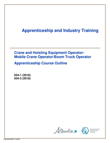
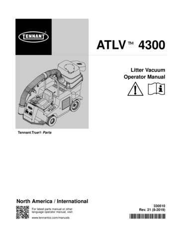
UNDERSTANDING HOW THE SWING HITCH OPERATES (PRIOR TO HITCHINGTO TRACTOR)With the swing stand loweredand the swing mast rearward todisengage the swing lock, graspthe hitch pins and rotate the“A” frame to simulate operation in a sharp turn. Releasethe hitch pins and slowly pullthe swing mast forward as itwould be pulled by the top linkduring lifting. Notice how onemast chain tightens causing the“A” frame and unit to realignand the spring on the lock linkis compressed to make theswing lock engage upon alignFigure 2. Swing Hitch Operationment. Now push the swingmast rearward against the locklink tab to disengage the swing lock and loosen the chains to allow sharp turns again. Thisdemonstrates how the top link of the tractor lift system switches the AERA-vator between thetrail and lift modes.CORRECTLY ADJUSTING THE HITCH TO THE TRACTORA category 1 hitch tractor is required with the lower links stabilized. With the AERA-vatorswing stand lowered connectthe lower lift links to the “A”Frame and top link to the swingmast. Push the lift control leveron the tractor to the completelylowered position.Lengthenthe adjustable top link until theswing mast closes tight againstthe “A” Frame and the AERAvator swing stand is lifted 1/8to 1/4 inch off the ground. Thiscauses the combined weight ofthe AERA-vator and the tractorhitch components to be transFigure 3. Hitch Adjustmentferred to the tines. This extended top link also causes the7
AERA-vator to tilt backwards when lifting allowing gravity to assist the swing chains in aligning the unit with the tractor. DO NOT ADD ADDITIONAL WEIGHT TO THE AERA-vatorOR APPLY DOWN PRESSURE TO THE TRACTOR LIFT LINKS DURING OPERATION. The geometry of tractor lift linkages varies, and a trial run over uneven ground is recommended. Ideally the swing lock will not engage when aerating over the crown of a hill andthe tractor hitch is always free to float upward at all times. The tines should clear curbsetc., when lifted. When lowering for operation, lower slowly until the tines touch the ground. Then swiftlypush the lift control lever on the tractor to the completely lowered position to instantlyunlock the hitch. This is especially true when lowering the unit in a sharp turn. Failure todo this may cause the swing hitch not to disengage, resulting in damage to the machineand/or turf damage. In the event the unit should fail to unlock for trail mode, stop the tractor and repeat the lowering procedure.DO NOT TURN THE TRACTOR WITH THE AERA-vator IN THE GROUND AND THESWING LOCK ENGAGED. DAMAGE TO EQUIPMENT MAY OCCUR! When operating diagonally downhill or transversely (sideways) on a hillside slope above5 the mast chains will not swing the unit uphill to center and lock on the tractor when theunit is lifted. Occasionally the unit will swing farther to the downhill side of the tractorcreating the hazard of tractor roll over. If the tractor ever seems unstable, immediatelylower the hitch and steer the tractor uphill or on a more level surface where it will centerand lock when lifted. Do not back the unit up with the AERA-vator touching the ground. Always disengage thePTO, raise the unit, back to desired location and then lower the machine and engage thePTO. The operating ground speed of the tractor will depend on the amount of soil agitation required. Slower tractor ground speed (lower gears) will be used for renovating in extremelyhard dry ground. Faster tractor ground speeds (higher gears) will be used for aeration workin normal conditions. To reduce the amount of soil agitation simply reduce the engineRPM. Three to four miles per hour is the most common speed range.PRE-OPERATION CHECK LIST(With the AERA-vator lowered and the tractor engine switched off.) Be sure that the implement is hitched to the tractor properly with all pins in place. Pin the swing stand in the up position. Be sure the driveline is correctly assembled. (The end stenciled as the tractor end is connected to the tractor and not to the AERA-vator). Check to see that the end yokes are8
locked to the tractor PTO and gearbox shafts. Drive shields must turn freely on the driveline. See that all shields are correctly installed. Remove any debris caught in the rotors. Check gearbox oil level before first operation and every 200 hours of operation thereafter.(Refer to operator maintenance section.)MAINTENANCE SAFETY Never attempt to clean, adjust, lubricate or perform any maintenance on the AERA-vatorwhile it is attached to the tractor or any other power source with the engine running. Read and understand all safety decals prior to performing any maintenance.Replace any safety decals that are not legible. Never attempt to clean, adjust, lubricate or perform any maintenance on the AERA-vatorwhile it is attached to the tractor in the raised position unless safety blocks are inserted under the frame. When not attached to the tractor, alwaysuse the lifting hook to hoist the machinefor maintenance. (See Figure 4). Use extreme caution when using lifting hook because center of gravity is affected by additional attachments and the unit mayshift rearward. LIFTING HOOKWhen installing tines, performing any rotor shaft service, or removing debris fromthe rotors, ensure that the rotor shaft doesSWING STANDnot rotate because a serious pinch injurycould occur.Figure 4. Swing Stand/Lifting Hook9
OPERATOR MAINTENANCE Check gearbox oil level before first operation and every 200 hours of operation thereafter.With frame level, remove oil plug on top side of gear box using 5/16” x 6” allen wrenchthrough access hole in frame. Use a piece of 1/16" dia. wire for checking fluid level. Pushwire into hole in gearbox until it hits the bottom. Pull out and measure the amount of oilleft on wire. There should be approx. 1-3/4" to 2" of oil on wire. If required, add 90wgear oil through plug in top of box until correct amount appears on wire. Replace top plugsecurely. Grease driveline parts after the number hours use as shown in the following chart.Figure 5 Drive Line Lube Chart The hitch flex joints at the top of the “A” frame and above the gearbox (see page 18)should be lubricated before first operation and weekly thereafter. After the first two hours of operation tighten all tines to 210-ft. lbs. Check for loose tinesdaily. When replacing lost or worn tines use a 15/16” extra deep socket (Socket is availablethrough our repair parts. Order # AE60T003) and torque to 210 ft. lbs. CHECK BELT TENSION every 4 hrs. of operation for the first 12 hrs. and every 100hrs. thereafter. Also, tighten belts if shaft hesitation is noticed during operation. Overtightening belts may cause damage to the machine. Be sure to re-install belt shield afterservicing. Use the applicable parts break down illustration pp.16-22 for maintenance removal, andassembly instructions. The AERA-vator shaft and rotor bearings are sealed and permanently lubricated requiringno routine maintenance.10
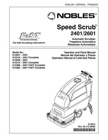
AE40L SERVICE INSTRUCTIONSROTOR SHAFTI. Removal & Disassembly (Clean the machine thoroughly with a pressure washer)A. Removal of Rotor Shaft Assembly from Main Frame.(This may require an overhead lift. For safety reasons, only lift the Aera-vator approximately twoinches above the work surface).1.2.3.4.Remove belt cover and drive belts.Remove skid shoe.Remove 3/8" carriage bolts holding end rotor shaft bearings (see Figure 6).Move frame slightly to right and lift off of rotor shaft assembly. Refer to Drive Train Components foridentifying listed components not shown, pg. 17Figure 6. Rotor Shaft AssemblyB. Disassembly of Rotor Shaft Assembly1. Remove the 1-1/8" hex jam nut from the shaft nearest to the damaged rotor (see Figure 6).2. Only remove the rotors and spacers as required to reach the damaged component and wipe the shaftclean before each rotor is removed. The rotor bearings have individual cones on each side that separateslightly before seal resistance is felt. It is important to keep the cones pushed tightly together to keepdirt from entering the bearing between the cones.CAUTIONIF THE ROTOR ASSEMBLIES DO NOT SLIP FREELY OFF THE ROTOR SHAFT DO NOT APPLYFORCE AGAINST THE ROTORS OR ROTOR TEETH. USE A BLUNT PUNCH OR BAR AGAINST THETHICK FACE OF THE INSIDE BEARING ADAPTER TO DRIVE THE ROTORS ALONG THE SHAFT.OTHERWISE THE SEAL IN THE TAPERED ROLLER BEARING WILL BE DESTROYED AND IT IS NOTREPLACEABLE (SEE FIGURE 7).11
C. Rotor Disassembly.1. With a pry bar remove the externalseals (see Figure 8) on both sides.Generally, seals are damaged and arenot reused.2. Remove the internal snap rings onboth sides.3. With the Rotor sitting on the presstable press out the bearing assembly.Figure 7. Disassembly of Rotor Shaft AssemblyII.Reassembly and Installation(Be careful to keep all components clean to prevent bearing grease contamination)A. Rotor Hub Re-Assembly.1. Install internal snap ringin one side of rotor.2. Press bearing and adapterassembly tight against thering (see Figure 9).3. Install second snap ring.4. Apply a ribbon of generalpurpose grease between thesnap ring ID and bearingadapter OD on both sides ofrotor.Figure 8. Rotor Assembly5. With the press toolinverted to fit the externalseals, press the seals inboth ends of the rotorwith the lips out. Wipeoff excess grease. Besure seals are not bent orcut and are seated firmly.If the seals are not tight,use a hammer andpunch to stake the hubfaces at about 90 intervals.Figure 9. Rotor Hub Assembly12
B.Assembly of Rotor Shaft.CAUTION1.2.3.IF THE BEARING ADAPTERS ARE NOT PRECISELY TIMED 180 DEGREES APARTIN EACH ROTOR AND ALIGNED BETWEEN ROTORS, SERIOUS DAMAGE WILLRESULT.Rotate the adapters in each rotor so the timing marks(see Figure 10) are phased 180 degrees apart with hexbores aligned.TIMING MARK FOR PHASINGTo assist with aligning timing marks between rotors, useBEARING ADAPTERS IN THEROTOR SHAFT ASSEMBLYchalk or marker to mark two rotor shaft flats 180degrees apart next to the threaded end. The selectedflats would have to align with the timing marks on any Figure 10. Timing Markrotors not removed during servicing.Install the required components in the sequence shown in Figure 6, double-checking the timingmark locations and spacer lengths (see following table) as each rotor is installed.SPACERLENGTH(inches)3 13/167 1/47 1/47 1/43 5/16ABCDECAUTIONCLEAN THE ROTOR SHAFT THOROUGHLY REMOVING ANY BURRS THAT WOULD KEEP THE ROTORASSEMBLIES FROM SLIDING ON FREELY. IF A BEARING ADAPTER JAMS, THE INTERNAL BEARINGSEAL COULD BE FORCED OUT AND IT IS NOT REPLACEABLE.NOTE: THE SPACERS MUST BE FULLY SEATED IN EACH ADAPTER COUNTER BORE BEFORETIGHTENING. DO NOT FORGET TO PLACE THE BEARING STAMPINGS ON EACH OF THE SHAFTBEARINGS DURING REASSEMBLY. ALSO, THE 3/8" CARRIAGE BOLTS SHOULD BE PLACED IN THEBEARING STAMPINGS ON THE DRIVE END OF THE SHAFT BEFORE THE SHEAVE IS REPLACED.4. Replace the 1-1/8" hex jam nut and rotate each rotor occasionally as the nut is being torqued to 350 ftlbs. If any rotor locks up, the bearing adapters in the rotor are probably not phased 180 degrees apart.D. Installation of Main Shaft AssemblyReinstall the rotor shaft into main frame by reversing the shaft removal steps outlined in I-A. Refer to Figure6 for correct location of bearing stampings, bolts, etc. Tighten the 3/8 flange lock nuts at each bearing to 35ft-lbs.CAUTIONTHE TWO STAMPINGS ON EACH BEARING ARE IN CONTACT WITH EACH OTHER IN THEASSEMBLY. NEVER SEPARATE THE BEARING STAMPINGS TO STRADDLE A FRAME MEMBER.13
E. After installing the belts and cover, run the machine and check for loose or improperly installedcomponents.TINE REPLACEMENTAssemble tines to rotor as shown in the following figure. Torque tines to 210 ft-lbs.AE50-058 (TINE)HW32020G8ZP5/8 LOCK WASHERGRADE 8HW20020G5ZPC5/8 NF HEX NUTNOTE: TORQUE TINESTO 210 FT-LBS.Figure 11. Tine ReplacementSEEDER MAINTENANCE(Supplied from Gandy) Remove bottom and rotors using snap latches, and wing nuts securing bearing retainers. Clean all surfaces. Lightly oil bearings periodically, more often if metering material with fines as powder may work into bearings. Some materials may build up on the hopper bottom, especially when atmospherichumidity is high. It may be wise to remove slide from bottom for cleaning. To remove slide, remove the four nuts, nylon washers and slide hanger. Re-assemble slide onto hopper after cleaning. For proper slide tension, gently drivethe hanger to the left, using a screw driver against the tab at the right end of thehanger. When the end of the hanger lines up with the scribed line on the hopperbottom, slide tension is correct. Bottom is ready for reinstallation.14
SEEDER CALIBRATIONCALIBRATIONIT IS THE RESPONSIBILITY OF THE OPERATOR TO ENSURE THATEACH BATCH OF SEED IS PROPERLY CALIBRATED IN THE SEEDERPRIOR TO APPLICATION. FAILURE TO DO SO MAY RESULT ININADEQUATE OR EXCESSIVE SEED RATES.AFTER PROPERCALIBRATION, IN ADDITION TO USING CONSISTENT SEED, THECHOSEN GAUGE SETTING AND GROUND SPEED MUST BEMAINTAINED TO OBTAIN THE CALIBRATED RATE.THE SEEDING RATE CHART PROVIDED IS TO SERVE ONLY AS INITIAL SETTINGGUIDE.I. GENERAL OBSERVATIONSEach product flows differently requiring calibration for each product. Variations in formulations,seed size, humidity, temperature and age of product may affect application rates.The applicator depends on gravity flow of the product particles through precisely adjustedopenings at each tube spout. The ground or electric driven rotor assures a constant flow whenturning and interrupts the flow when it stops, allowing only the particles in the rotor segmentexposed to the openings to flow out.To close the hopper bottom openings, rotate the shut off lever counter-clockwise until the slidestop contacts the hopper stop. To open the hopper bottom openings, rotate the lever clockwiseuntil the slide gauge cam contacts the hopper stop. The opening increases as the cam is rotatedfrom 0 to 80.15
II. CALIBRATION PROCEDUREEstablish the desired application rate based on lbs. per 1000 sq. ft. (Divide lbs. per acre by 43.6 toconvert to lbs. per 1000 sq. ft. or refer to conversion chart (Figure 2)).CONVERSION CHARTLbs/1000 sq.ft - to - Lbs/acrePER 1000 sq.ftTenths of a 0475Lbs/AcreFigure 2. Conversion ChartA. After considering the site to be seeded (shape, soil texture, slope, obstacles, etc.), set yourtractor ground speed (MPH). Select a gear setting that will provide the desired MPH andmaintain a PTO speed between 500 and 600 RPM or as required for the degree of tillagedesired. The ground speed can be verified by determining the time required to travel a distanceof 200 ft. per the following speed/time chart:Speed MPH11½2Time Requiredper 200’2 min 16 sec1 min 31 sec1 min 8 secSpeed MPHTime Requiredper 200’Speed MPHTime Requiredper 200’2½33½455 sec45 sec39 sec34 sec4½55½630 sec27 sec25 sec23 secB. Fix the preliminary cam gauge setting for your selected seed using your best judgment.C. Collect and weigh the seeder output for 1000 sq. ft.a. Place seed in hopper with control lever closed.b.Place empty container on one of the spouts to catch seed (To prevent loss of seed, blockoff other spouts).c. Start motord.After waiting 15 to 20 seconds, open the control lever for the time required to travel 200ft. that corresponds with the set speed (see speed/time chart).e. Close the control lever after it has been open the exact time required.f. Weigh the collected seed and multiply times 23 for total output and compare to thedesired rate per 1000 sq. ft.g. Adjust the cam gauge and repeat the procedure as required.16
WARRANTY INFORMATIONONE YEAR LIMITED WARRANTYFIRST PRODUCTS INC. WARRANTS THIS PRODUCT TO BE FREE OF DEFECTS INMATERIALS AND WORKMANSHIP FOR A PERIOD OF TWELVE MONTHS FROM THEORIGINAL DELIVERY DATE. THIS WARRANTY DOES NOT COVER PARTS CAUSEDTO BE DEFICIENT DUE TO NORMAL WEAR, MISUSE, ACCIDENTS, OR LACK OFPROPER MAINTENANCE.ANY PARTS THOUGHT TO BE DEFECTIVE MUST BE RETURNED TO THEDEALER/DISTRIBUTOR FOR WARRANTY CONSIDERATION JOINTLY WITH FACTORYREPRESENTATIVES. A RETURN AUTHORIZATION NUMBER MUST BE OBTAINEDAND CLEARLY MARKED ON ALL PACKAGES OF PARTS REQUIRING RETURN TO THEFACTORY.THE OBLIGATION OF FIRST PRODUCTS INC. UNDER THIS WARRANTY SHALL BEEXCLUSIVELY LIMITED TO REPLACEMENT OF PARTS DETERMINED TO BEDEFECTIVE BY FIRST PRODUCTS INC. WITH FREIGHT PREPAID. IN NO EVENT SHALLFIRST PRODUCTS INC. BE LIABLE FOR INDIRECT, INCIDENTAL, OR CONSEQUENTIALDAMAGES IN CONNECTION WITH THE USE OF THIS PRODUCT.FIRST PRODUCTS INC. RESERVES THE RIGHT TO MAKE CHANGES OR ADDIMPROVEMENTS TO ITS PRODUCTS AT ANY TIME WITHOUT OBLIGATION TO MAKESUCH CHANGES OR IMPROVEMENTS ON PRODUCTS SOLD PREVIOUSLY.17
MAIN FRAME ASSEMBLYITEM NO.ORDER NO.DESCRIPTIONITEM NO.ORDER NO.DESCRIPTION1AE26-034ROTOR SHAFT-4013AE50-0862B 4.65 X 1-1/8" HEX BORE SHEAVE2HW32036G5ZP1-1/8" LOCKWASHER14AE23-1523HW25036G5ZPF1-1/8"-12 JAMNUT N.F.15AE24-0294AE81-012ROTOR COMPLETE16AE50-114INPUT SHIELD-40L (NOT SHOWN)RIGHT END SPACER (3-5/16")DANGER HAZARD DECAL (NOT SHOWN)5AE24-011AE50-076THROWN OBJECT HAZARD6AE24-027LONG SPACER (7-1/4")DRIVE END SPACER (3-13/16")1718AE50-124AE 40 DECAL7HW03012032G5ZPC3/8" X 1" CARRIAGE BOLT19FB50-0688HW22012G5ZPC3/8" FLANGE LOCKNUT20AE50-1139AE80-094MAIN FRAME -40L21AE50-07410AE50-09472MM X 4 HOLE FLANGE22AE50-07711AE50-0901-1/8" HEX BEARING23AE50-032F.P. LOGO DECAL (NOT SHOWN)SWING FRAME HAZ. WARNING (NOT SHOWN)GENERAL CAUTION (NOT SHOWN)540 PTO ONLY (NOT SHOWN)U.S. PATENT DECAL (NOT SHOWN)12AE50-063AERA-vator DECALNOT SHOWN:CAUTION STICKER (21) ON EACH SIDE OF INPUT SHIELD (14),540 PTO ONLY STICKER (22) ON TOP OF INPUT SHIELD,AND DANGER HAZARD DECAL (16) UNDER INPUT SHIELD.182392012WARNING11* TO PREVENT A THROWN OBJECT HAZARD,DO NOT ENGAGE PTO IN LIFTED POSITION.17613* TO PREVENT A ROLL OVER HAZARD, DONOT LIFT UNIT ON HILLSIDES.AERA-vator191045AE-4023178BOTH BEARING FLANGES THIS SIDEOF END PLATE. TYPICAL EACH END.1518
DRIVE TRAIN COMPONENTSITEM NO.ORDER NO.DESCRIPTIONITEM NO.ORDER NO.DESCRIPTION1AE50-006COUPLER CHAIN CPT.19AE24-047COUPLER SHIELD2AE50-007#40-2 CHAIN CONN.2
With the AERA-vator swing stand lowered connect the lower lift links to the "A" Frame and top link to the swing mast. Push the lift control lever on the tractor to the completely lowered position. Lengthen the adjustable top link until the swing mast closes tight against the "A" Frame and the AERA-vator swing stand is lifted 1/8